INSTITUTO TECNOLÓGICO Y DE ESTUDIOS SUPERIORES DE MONTERREY
PRESENTE.-Por medio de la presente hago constar que soy autor y titular de la obra denominada
", en los sucesivo LA OBRA, en virtud de lo cual autorizo a el Instituto Tecnológico y de Estudios Superiores de Monterrey (EL INSTITUTO) para que efectúe la divulgación, publicación, comunicación pública, distribución, distribución pública y reproducción, así como la digitalización de la misma, con fines académicos o propios al objeto de EL INSTITUTO, dentro del círculo de la comunidad del Tecnológico de Monterrey.
El Instituto se compromete a respetar en todo momento mi autoría y a otorgarme el crédito correspondiente en todas las actividades mencionadas anteriormente de la obra.
De la misma manera, manifiesto que el contenido académico, literario, la edición y en general cualquier parte de LA OBRA son de mi entera responsabilidad, por lo que deslindo a EL INSTITUTO por cualquier violación a los derechos de autor y/o propiedad intelectual y/o cualquier responsabilidad relacionada con la OBRA que cometa el suscrito frente a terceros.
Characterization of a Domestic Horizontal Ground Sink Heat
Pump System -Edición Única
Title
Characterization of a Domestic Horizontal Ground Sink
Heat Pump System -Edición Única
Authors
Angel Adolfo Valerio Velázquez
Affiliation
Tecnológico de Monterrey, Campus Monterrey
Issue Date
2008-12-01
Item type
Tesis
Rights
Open Access
Downloaded
19-Jan-2017 02:09:14
SUPERIORES DE MONTERREY
CAMPUS MONTERREY
DIVISIÓN DE INGENIERÍA Y ARQUITECTURA PROGRAMA DE GRADUADOS EN INGENIERÍA
CHARACTERIZATION OF A DOMESTIC HORIZONTAL GROUND
SINK HEAT PUMP SYSTEM
TESIS
PRESENTADA COMO REQUISITO PARCIAL PARA OBTENER EL GRADO ACADÉMICO DE:
MAESTRO EN CIENCIAS
ESPECIALIDAD EN INGENIERÍA ENERGÉTICA
POR:
ANGEL ADOLFO VALERIO VELÁZQUEZ
MONTERREY
CAMPUS MONTERREY
DIVISIÓN DE INGENIERÍA Y ARQUITECTURA PROGRAMA DE GRADUADOS EN INGENIERÍA
Los miembros del comité de tesis recomendamos que el presente proyecto de tesis del Ing. Angel Adolfo Valerio Velázquez sea aceptado como requisito parcial para obtener el grado académico de Maestro en Ciencias con especialidad en:
INGENIERÍA ENERGÉTICA
Comité de Tesis:
Dr. Carlos Iván Rivera Solorio Sinodal
MC. César Ulises Treviño Treviño Sinodal
Dr. Oliver Matthias Probst Oleszewski Asesor
Dr. Joaquín Acevedo Mascarúa
Director del Programa de Graduados en Ingeniería y Arquitectura
Para
Claudia Adrileth Luz María y Ángel Angélica y Adolfo Matilde y Luz Angélica
A Dios, a San Judas Tadeo y a la Virgen de Guadalupe por ayudarme a llegar a este momento.
A la ingeniera Claudia Adrileth Cambero (La Changuita), gracias por ser mi mayor inspiración, por recordarme el objetivo de estudiar una maestría y levantarme cuando ya no tenia ganas de seguir, por los consejos y las palabras de apoyo, por la comida, por las noches de parranda, por siempre estar a mi lado; Gracias por aceptar pasar tu vida conmigo, TE AMO.
A la ingeniera Angélica Velázquez (La Bucky), gracias por ser mi mejor amiga, por recordarme siempre a que sabe un hogar, por tu amor, por las interminables pláticas, por tu dedicación, esmero y por haber formado y mantenido unida a nuestra familia. Sin ti esto no tendría sentido.
Al maestro Adolfo Valerio Payán (El Rudolph), gracias por ser mi ejemplo, por apoyarme incondicionalmente, por no juzgar mis decisiones, por siempre ser un impulsor, por creer siempre en mi, por enseñarme con el ejemplo que nada es gratis en esta vida y solo los decididos logran sus metas. Sin ti esto no hubiera sido posible.
Al doctor Ángel Barojas (El Fichi-Fuchi), a la enfermera Luz María Trejo (Mama Go) y a la señora Evelia Velázquez (La Cheves Frías) por su recuerdo y enseñanzas que siempre vivirán en mi, gracias por seguirme cuidando.
Al ingeniero Alfonso Valerio y la enfermera María Luisa Payán por darme la oportunidad de conocerlos y llegar a quererlos.
A la profesora Matilde Velázquez (La Chatanuga) gracias por ser mi segunda madre y a Luz Angélica Velázquez (Lucianita) gracias por ser mi hermana.
Al doctor Oliver Probst por sus consejos y su incondicional apoyo, gracias por ser un formador.
Al doctor Arturo Molina por confiar en mí y darme la oportunidad de creer en lo que hago.
Al doctor Carlos Rivera por sus consejos, gracias por presentarme el problema que parecía inalcanzable desde un punto de vista posible de lograr.
Al maestro Ulises Treviño gracias por inspirar gran parte de esta tesis.
A Jaime Martínez y Jorge Elizondo muchas gracias por demostrarme que el trabajo duro siempre genera buenos resultados.
A Planta Física y sus ingenieros por creer y financiar este proyecto.
A los profesores de la maestría, a la gente del departamento de física, a las personas de servicios generales, a los vendavales y colegas de la maestría, a los IFIs, MIEs, MCPs, IMEs y IMTs que se involucraron en este proyecto.
“The planet has a fever. If your baby has a fever, you go to the doctor. If the doctor says you need to intervene here, you don't say, 'Well, I read a science fiction novel that told me it's not a problem.' If the crib's on fire, you
don't speculate that the baby is flame retardant. You take action…!”
Dedicatoria ...ii
Agradecimientos... iii
General Index ...v
Figures Index... vii
Tables Index ...x
Summary ... 1
1. Chapter One - Introduction... 2
1.1 Introduction to the Document... 2
1.2 Generalities ... 3
1.3 Previous Research Work on GSHP systems at Tecnológico de Monterrey... 4
1.4 The Research Group on Sustainable Edification and Low Temperature Geothermic Studies 9 1.5 Research Context ... 9
1.6 Justification of the this research... 9
1.7 Research Problem Formalization... 11
1.8 Research General Objective... 11
1.9 Specific Targets ... 11
2. Chapter Two - State of the Art... 13
2.1 HVAC systems history: from ice-making to GSHP ... 13
2.2 GSHP Review 1995 – 2008 ... 22
3. Chapter Three - Theoretical Framework ... 43
3.1 Greenhouse Gases and Global Warming ... 43
3.2 Kyoto Protocol and the Clean Developing Mechanisms... 45
3.3 Energy Star for Buildings and LEED... 49
3.4 LEED for Homes ... 54
3.5 What is a GSHP system?... 56
3.6 A Variety of GSHP Systems... 57
4. Chapter Four - Experimental Facility Description... 62
4.1 System Description ... 62
4.2 Fitting-out Activities ... 67
4.3 Soil Proprieties Measurement ... 68
4.4 Water Pumping Characteristics ... 71
4.5 Calibration of the Thermocouples Type K... 74
4.6 Calibration of the Anemometer ... 78
4.7 Installation of Sensors and Data Logger... 80
4.8 Data Logger Programming... 84
5. Chapter Five - GSHP Characterization Model ... 89
5.1 Introduction... 89
5.2 General GSHP Thermodynamic Model ... 90
5.3 GSHP Thermodynamic Model for the study case... 97
5.4 Subsoil Heat Disposal and Temperature Profile - Ground Coupled Heat Exchanger (GCHE) Model 102 6. Chapter Six - Continuous Cooling Load Calculation Model (AVOP2008 Model)... 110
6.1 Introduction... 110
6.2 Methodology for instantaneous cooling load calculations (AVOP2008 Model) ... 113
6.3 The Escamilla study case ... 122
7. Chapter Seven - Results ... 125
7.1 Stage 1- Instrumentation and Environmental Data Manipulation ... 125
7.2 Stage 2- Thermodynamic States Determination and Performance Calculation ... 131
7.3 Stage 3- Ground Heat Rejection and Temperature Profile... 140
Conclusions and Future Work ... 144
Nomenclature ... 148
References ... 149
Appendix A - State of the Art Statistics ... 163
Topic Statistics... 163
Publications per Year... 165
Appendix B - Green Design based on Rapid Product Realization Methodology ... 166
Appendix C - Heating Mode Design ... 173
Appendix D - Thermodynamic EES Model... 179
Appendix E - GCHE Matlab Model... 181
Appendix F - AVOP2008 Clearness Factor Matlab Model... 184
Appendix G - Experiences with GSHP Computer Aided Engineering Simulation using FluentTM... 186
Appendix H - Performance Effect of Installation Materials... 191
Pipe without thickness ... 192
Pipe with finite thickness... 193
U-Tube ... 196
Lessons learned... 197
Appendix I - Tecnologico de Monterrey U-Tube Model Case Study Simulation with FluentTM... 198
U-Tube FluentTM simulation ... 200
FluentTM methodology validation... 200
Figure 1-1 Scheme of the problem solved by the Israel’s thesis ... 5
Figure 1-2 U-Tube heat exchange for a U-pipe length of 60m, a water flow rate of 0.3 kg/s and ¾”, 1”... 5
Figure 1-3 U-Tube heat exchange with ¾” pipe diameter and 0.3, 0.2 and 0.1 kg/s water flux ... 6
Figure 1-4 Total and unit length heat rejection of a 100m U-Tube with a flow rate of 0.3 kg/s and ½”, ¾”, 1”, 1 ½” pipe diameter ... 6
Figure 1-5 U-Tube exit water temperature and ground temperature with 0.3 kg/s water flux and ½”, ¾”, 1”, 1 ½” pipe diameter ... 7
Figure 1-6 Daily 6, 8, 10 hours operation cycles (0.3 kg/s water flux and ½”, ¾”, 1”, 1 ½” pipe diameter)... 7
Figure 1-7 Temperature contours obtained for a single ground tube... 8
Figure 1-8 Research Group on Sustainable Edification and Low Temperature Geothermic Studies Logo... 9
Figure 1-9 GSHP systems savings ... 10
Figure 2-1 (a) Willian Cullen (b) Thomas Moore (c) Oliver Evans ... 13
Figure 2-2 Ice making machine invented in Apalachicola by Dr John Gorrie ... 14
Figure 2-3 Willis Carrier with his first chiller ... 15
Figure 2-4 Frederick McKinley Jones with his system for refrigerating trucks ... 18
Figure 2-5 First ASHRAE Meeting ... 20
Figure 2-6 Sketch of Mai and Fisher’s proposed GSHP system... 22
Figure 2-7 The geometry of a finite line source in a semi-infinite medium and a schematic of two inclined boreholes... 28
Figure 2-8 Schematic diagram of the SGSHPS ... 33
Figure 2-9 Schematic diagram of the GSHP system in the heating mode. (I) compressor; (II) condenser; (III) capillary tube; (IV) evaporator; (V) fan coil units; (VI) ground heat exchanger; (VII) reversing valve ... 36
Figure 2-10 The main components and schematic of the SAGSHPGHS ... 38
Figure 2-11 Schematic of the two heat pump versions that are compared in this study based on different climatic conditions of the house (a, b). Also shown is a third, more energy conserving version based on distributed water-to-air heat pumps (c)... 40
Figure 3-1 Illustration of the greenhouse effect... 44
Figure 3-2 Global carbon dioxide variations... 44
Figure 3-3 World carbon dioxide emissions ... 45
Figure 3-4 Hemispheric temperature increase ... 45
Figure 3-5 Results of the Montreal Protocol... 46
Figure 3-6 World map: Kyoto Protocol participation... 47
Figure 3-7 A world of climatic offenders ... 48
Figure 3-8 Energy Star Logo ... 50
Figure 3-9 Andy Watts in the Halloween Parade of Vermont... 51
Figure 3-10 LEED Logo... 52
Figure 3-11 LEED for homes Logo... 55
Figure 3-12 A simple stylized diagram of a heat pump's vapor-compression refrigeration cycle: 1) condenser, 2) expansion valve, 3) evaporator, 4) compressor ... 56
Figure 3-13 ITESM Escamilla’s GSHP system cycle in cooling mode and heating mode... 57
Figure 3-14 Scheme of a ground-water heat pump system ... 58
Figure 3-15 Scheme of a vertical borehole ground-coupled heat pump system... 59
Figure 3-16 Scheme of a surface-water heat pump system ... 60
Figure 3-17 Scheme of a standing column well system... 60
Figure 3-18 Scheme of a horizontal ground-coupled heat pump system ... 61
Figure 4-1 Escamilla’s Field Igloo Location [Approximately trip: 950 meters]... 62
Figure 4-2 Graphical description of the Escamilla’s Field Igloo ... 63
Figure 4-3 Escamilla’s Field GSHP condenser unit ... 64
Figure 4-4 Escamilla’s Field GSHP refrigerant-to-water heat exchanger and thermocouples ... 64
Figure 4-5 Escamilla’s Field GSHP exterior temperature sensor... 65
Figure 4-8 Evaporating unit and its thermostat ... 67
Figure 4-9 State of the electric and electronic devices ... 68
Figure 4-10 Thermal conductivity experiment sketch... 70
Figure 4-11 a) Running the water flow experiment b) Water flow experiment array (1) Water pump (2) Refrigerant-to-water heat exchanger (3) Pressure well (4) Cut pipe section where the experiment was made ... 71
Figure 4-12 Horizontal multistage centrifugal pump model ESPA Tecno 05 ... 73
Figure 4-13 ESPA Tecno 05 performance ... 73
Figure 4-14 Data Logger cleaning and maintenance ... 74
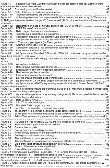
Figure 4-15 Thermocouple calibration test equipment... 75
Figure 4-16 Connection diagram of the thermocouple calibration test ... 75
Figure 4-17 Comparison instruments during the calibration (a) Digital thermometer (b) Analytical thermometer (c) Thermocouples type K (d) Steam generator ... 76
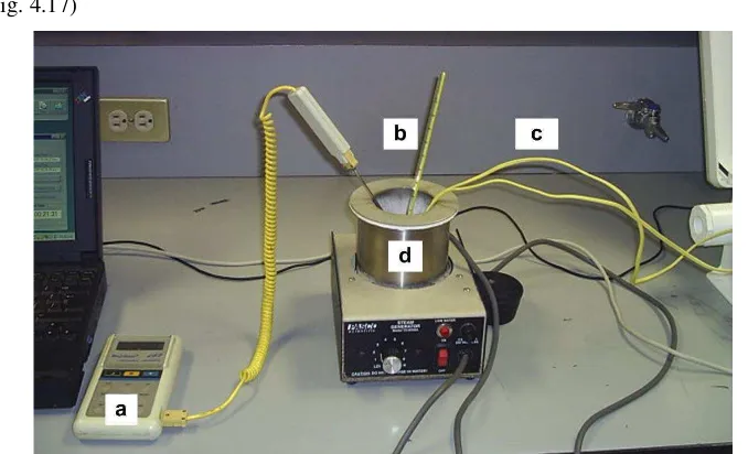
Figure 4-18 Anemometer model NRG-40 ... 78
Figure 4-19 Connection diagram of the anemometer calibration test ... 79
Figure 4-20 Anemometer calibration test ... 79
Figure 4-21 (a) Pyranometer Campbell CSI model LI200X (b) Location of the pyranometer on the top of the Escamilla’s Field Igloo... 80
Figure 4-22 (a) Anemometer NRG-40 (b) Location of the anemometer 3 meters above the ground surface ... 81
Figure 4-23 Wiring lines installation ... 81
Figure 4-24 Underground thermocouple connection... 82
Figure 4-25 Encapsulation of the thermocouple connections ... 82
Figure 4-26 Heat exchanger thermocouples ... 83
Figure 4-27 Exterior temperature thermocouples ... 83
Figure 4-28 Electric ground and Data Logger installation ... 83
Figure 4-29 (a) Selection of CR10X Data Logger screenshot (b) Scan Interval screenshot ... 84
Figure 4-30 (a) Pyranometer LI200X programming screenshot (b) Wind Speed Sensor NRG-40 programming screenshot... 84
Figure 4-31 (a) Internal temperature programming dialog-box (b) Maximum possible thermocouples installed in the Data Logger dialog-box ... 85
Figure 4-32 (a) Internal temperature programming dialog-box (b) Maximum possible thermocouples installed in the Data Logger dialog-box ... 86
Figure 4-33 Data Logger’s wiring ... 87
Figure 4-34 CR10X Installation diagram ... 87
Figure 4-35 Complete Data Logger program ... 88
Figure 5-1 Carnot’s TS diagram for a common heat pump... 91
Figure 5-2 TS diagram for a common heat pump vapor compression cycle ... 91
Figure 5-3 TS diagram for a common heat pump vapor compression cycle ... 98
Figure 5-4 Adolfo Valerio measuring pressure in the compressor and evaporator using the manifold ... 99
Figure 5-5 Parallel pipe-loop horizontal GCHE and its solution area in the soil ... 103
Figure 5-6 Finite-difference grid for the model domain ... 103
Figure 5-7 General interior node ... 104
Figure 5-8 Energy balance for each pipe section... 106
Figure 5-9 Nodal energy balance for the pipe isothermal influence region... 108
Figure 6-1 Cooling load calculation methodology ... 113
Figure 6-2 Thermal Circuit for non-opaque surfaces ... 116
Figure 6-3 Thermal Circuit for convective and radioactive effect in the surface ... 119
Figure 6-4 Draft of the igloo structure considered in this study... 122
Figure 6-5 Sketch of the transfer area simplification... 123
Figure 6-6 Ground thermal resistance values ... 123
Figure 7-1 Thermocouple calibration - cooling test (ATT - analog thermometer, DTT - digital thermometer temperature, TT - tested thermocouples type K) ... 126
Figure 7-2 Thermocouple calibration - heating test (ATT - analog thermometer, DTT - digital thermometer temperature, TT - tested thermocouples type K) ... 126
[image:11.612.91.522.57.719.2]Figure 7-5 Interior (IAT) and exterior (EAT) air temperature - The interior air temperature is not constant due to the fact that the thermostat was broken and the HVAC system does not have
temperature regulation ... 129
Figure 7-6 Inlet (IWT) and outlet (OWT) ground heat exchanger water temperature - This measurements presents a skip on October 8th of about 3 degrees both in the inlet and outlet measurement points, this anomaly will be studied in future explorations ... 129
Figure 7-7 Ground temperature - The temperature skip presented in Fig. 7.6 appears on the ground temperature measurement thermocouple too ... 130
Figure 7-8 Wind Speed - The wind speed sensor reports a maximum wind speed of 1.4 m/s at 2 meters above the ground... 130
Figure 7-9 Extracted cooling load calculation using AVOP2008... 132
Figure 7-10 Extracted cooling load correlation (Experimental - AVOP2008)... 132
Figure 7-11 Extracted cooling load calculation using CLTD-SCL-CLF ASHRAE and the effect of the clearness factor on the results ... 133
Figure 7-12 Extracted cooling load correlation (Experimental - CLTD-SCL-CLF without clearness factor)... 133
Figure 7-13 Extracted cooling load correlation (Experimental - CLTD-SCL-CLF with clearness factor) ... 133
Figure 7-14 Steady-state thermodynamic states of the GSHP system, first and second law efficiencies ... 135
Figure 7-15 Experimental subsoil heat rejected versus the result obtained with the EES model... 136
Figure 7-16 AVOP2008 Extracted cooling load versus the result obtained with the EES model ... 136
Figure 7-17 Experimental coefficient of performance (COP-AVOP2008)... 138
Figure 7-18 AVOP2008 COP versus the result obtained with the EES model ... 138
Figure 7-19 Energy efficiency ratio (EER - AVOP2008) ... 139
Figure 7-20 AVOP2008 EER versus the result obtained with the EES model... 139
Figure 7-21 Heat rejected rate to ground comparison - Experimental calculation (Exp) versus GCHE Model (Anl) ... 141
Figure 7-22 Heat rejected rate to ground correlation (Experimental - GCHE Model) ... 141
Figure 7-23 Heat rejected rate to ground per pipe unit lenght comparison - Experimental calculation (Exp) versus GCHE Model (Anl) ... 142
Figure 7-24 Ground temperature (40 cm from the first loop at 10 m pipe lenght) comparison - Experimental calculation (Exp) versus GCHE Model (Anl) ... 142
Figure 7-25 Ground temperature correlation (Experimental - GCHE Model)... 142
Table 2-1 GSHP authors and their contributions to different sub-fields of interest... 25
Table 3-1 LEED authors ... 54
Table 4-1 Specific heat experiment results ... 69
Table 4-2 Thermal conductivity experiment results (Gutierez, 2004) ... 70
Table 4-3 Water flow experiment results... 71
Table 4-4 ESPA Tecno 05 pumping characteristics... 73
Table 4-5 Thermocouple calibration report for cooling experiment... 77
Table 4-6 Thermocouple calibration report for heating experiment ... 78
Table 4-7 Anemometer calibration report... 80
Table 5-1 Escamilla’s Field main components characteristics... 98
Table 6-1 Cooling load calculation state of the art ... 111
Table 6-2 Volumetric infiltrated air flow [Kraider et al, 2002]... 124
Summary
1.
Chapter One - Introduction
“Ground source heat pumps are electrically powered systems that tap the stored energy of the greatest solar collector in existence: the earth… These systems use the earth's relatively constant temperature to provide heating, cooling, and hot water for homes and commercial buildings…”
Jim Bose Executive Director IGSHPA
1.1 Introduction to the Document
Due to climatic change, population growth and people’s desire to live in a comfortable environment, the demand of air conditioning systems has increased significantly in recent years and especially in large cities with hot climates such as Monterrey (Nuevo León, Mexico), with high average temperatures in the summer, peak temperatures of up to 40°C and near-zero temperatures during the short winter period,. Under such climatic conditions it is evident that some kind of air conditioning is required, but providing interior air comfort in a sustainable way remains a challenge.
Among the many available sustainable energy sources there is geothermy. Geothermal energy is the thermal energy contained in the stone, ground and air that exists in the soil and the subsoil. Geothermal energy (if used wisely staring with the design phase), is an energy resource with significant cost, reliability and environmental advantages over conventional energy sources (IGSHPA, 2006). As pointed out by Rantala (2005) the ground at depths as low as a few meters has an almost constant temperature over the year, This means that in the summer the temperature of the underground is lower than the exterior air temperature and in the winter it is warmer, providing a useful storage effect which can be used for both cooling and heating.
AC-systems that use an heat exchanger connected to the subsoil operate with major efficiencies, these systems are known as GSHP [Ground Source/Sink Heat Pumps]; these systems can be managed to run in a completely passive way that means the exterior environmental fluctuations do not impact on the system performance (Zogou and Stamatelos, 2007). Heat pump technology has received an increasing attention in recent years; initially these systems were very popular in rural residential applications, principally where the energetic requirements are the main consideration. Nevertheless, the recent improvements that have occurred in heat pump technology and the modern procedures for installation and maintenance have extended the market to the urban and commercial applications.
1.2 Generalities
The industrial revolution marks the beginning of the intensive use of fossil fuels to supply energy to the machines and devices used by modern society. The burning of these fuels using conventional technologies emits gases that damage the natural environment and harm the health of the human being. There are other adverse consequences that are undeniable, e.g. the gradual decline of fossil resources and climate change. These problems have triggered an intensive research about energy engineering with the goal of using less electric power and thereby burning less fossil fuel in our daily activities.
Many residences in the United States, Canada and a great part of the European Union use GSHP systems for residential air conditioning (AC), both for heating houses in the winter and cooling them in the summer, obtaining also warm sanitary water as a secondary product (IGSHPA, 2006). The GSHP systems take advantage of the ground’s thermal inertia to cool or to warm water, which is typically used as the heat exchange medium for the refrigerant fluid. There are nearly 500,000 geothermal residential heat pumps installed in the United States nowadays (EERE, 2008). Theoretically, GSHP systems are 50% - 70% more efficient in heating and 20% - 40% more efficient in cooling and can reduce the use of the electricity for 40% - 25% compared to traditional electrical systems for heating and cooling respectively (GeoThermal, 2007). The projects conducted with this technology have registered payback values from 4 to 10 years, and reduce emission of up to 72% when compared to an electrical heating system (IGSHPA, 2006).
and the reason for which it is considered to be more efficient is the fact that the temperature fluctuations in the ground are very small compared to the ambient air exterior temperature fluctuations; this is due to the great thermal inertia of the ground. Since the temperature of the soil is close to the temperature range acceptable for human comfort, the coefficient of performance of the heat pump remains at high values across the year (Minea, 2006).
A GSHP system is costlier and needs more space for its installation than a conventional air conditioning system; nevertheless, the initial investment will be recovered in a short period due to savings in electricity costs. Moreover, the implementation of a GSHP system may reduce the maximum electricity demand and therefore reduce demand charges in the case of tariffs that account for demand. In Mexico, this is the case for residential consumers classified as “high consumption customers”. In those cases, the recovery of the investment is even more rapid. From a national grid perspective, the demand reduction provides by GSHP systems (beside reducing the consumption of electric energy), are of special importance during the warm months of the year where typically additional generation capacity has to be made available, leading to increased power flows on the transmission lines and increased transmission losses. Any reduction in peak demand therefore also ultimately leads to a reduction in overall consumption and less pollution.
1.3 Previous Research Work on GSHP systems at
Tecnológico de Monterrey
A small research group in low temperature geothermy led by physics professor Dr. Probst has been working at ITESM campus Monterrey since 2003, being the most important contributions the following:
1.3.1Master thesis of Israel Gutiérrez
Figure 1-1 Scheme of the problem solved by the Israel’s thesis
Initial exploration of the heat transfer of the vertical U-pipe was performed in this work running the Matlab numerical model program of the ground exchanger designed by Israel Gutiérrez (2003). The results presented below were obtained adjusting the main parameters, such as pipe length, pipe diameter, and flow rate.
For L = 60m = U-pipe length [total pipe length = 120 meters]
0 1 2 3 4 5 6 7
0 5 10 15 20 25 30
Operating time (hr)
Q
(
to
ns
)
d=3/4 inches d=1 inch d=1 inch 1/2
Figure 1-2 U-Tube heat exchange for a U-pipe length of 60m, a water flow rate of 0.3 kg/s and ¾”, 1”
d=3/4 L = 60m 0 1 2 3 4 5 6 7
0 5 10 15 20 25 30
Operating time Q ( to n ) flux=0.1 kg/s flux=0.2 kg/s flux=0.3 kg/s
Figure 1-3 U-Tube heat exchange with ¾” pipe diameter and 0.3, 0.2 and 0.1 kg/s water flux
As expected, initial (t=0) heat dissipation rates are directly proportional to the flow rate since for low ground temperatures the dissipation rate is limited by the heat advection through the pipes, not by ground conduction. However, after about 20 minutes all curves converge against the same steady-state value (less than 1 refrigeration ton). This situation corresponds to the fact that now the soil conduction limits the heat dissipation. As pointed out by Israel Gutiérrez (Gutiérrez, 2003) it is not convenient to increase the flow rate too much, since increasing the water flow leads to a rise in pressure losses.
For L = 100 m [total pipe length= 200 meters]
Q (ton) = f(t) for each tube diameter
0 1 2 3 4 5 6
0 10 20 30 40 50 60
Time (hr) Q ( to n) d=1/2 inch d=3/4 inch d=1 inch d=1 inch 1/2
Q (kW/m) =f (t) for each tube diameter
0 0.01 0.02 0.03 0.04 0.05 0.06 0.07 0.08 0.09 0.1
0 10 20 30 40 50 60
Operating time (hr)
Q ( kW /m ) d=1/2 inch d=3/4 inch d=1 inch d= 1 inch 1/2
Figure 1-4 Total and unit length heat rejection of a 100m U-Tube with a flow rate of 0.3 kg/s and ½”, ¾”, 1”, 1 ½” pipe diameter
Texit (°C) =f(t) for each tube diameter 0 5 10 15 20 25 30 35 40
0 10 20 30 40 50 60
Operating time (hr)
T ex it (° C ) d=1/2 inch d=3/4 inch d=1 inch d=1 inch 1/2
Tground = f(t) for each tube diameter
0 5 10 15 20 25 30 35
0 10 20 30 40 50 60
Operating time (hr)
T gr ou nd ( °C ) d=1/2 inch d=3/4 inch d=1 inch d=1 inch 1/2
Figure 1-5 U-Tube exit water temperature and ground temperature with 0.3 kg/s water flux and ½”, ¾”, 1”, 1 ½” pipe diameter
For a same operation cycle, the exit temperature of the water decreases when the U-tube exchanger is larger. This geometry of U-tube heat exchanger allows for a mean dissipation rate of 2 tons of refrigeration during an 8-hours-a-day working cycle.
1.3.2Other reports available on GSHP systems at Tecnológico de Monterrey
• Internship report by Adrien Taillebois (University of Pau, France). The main result of this work was the design and installation of a 1 refrigeration ton mini-split AC system coupled with a 200 m total length horizontal heat exchanger in the subsoil. This report also contains first performance measurements on an experimental GSHP system at Tecnológico de Monterrey.
• David Solario’s design project, which consisted in the installation of a first data acquisition system, using four thermocouple type K temperature sensors, a pyranometer and two voltage amplifiers. The system was tested and first real-time measurements on the GSHP system were conducted which remained, however, inclusive.
• In the design project of Alfredo Jaime and Alejandro Duhart first continuous performance measurements were conducted on the experimental GSHP system originally set up by Arien Taillebois.
• Internship report by Florent Galliot (University of Pau, France). Florent worked on the thermodynamically analysis of the refrigeration cycle using Engineering Equation Solver and heat exchange modeling of horizontal ground coupled pipes using the commercial CFD (computational fluid dynamics) solver Fluent. A sketch of a typical result of these simulations, showing temperature contours at the pipe surface and selected planes of interest within the simulation volume, is shown in Figure 1-7.
1.4 The Research Group on Sustainable Edification and
Low Temperature Geothermic Studies
The Research Group on Sustainable Edification and Low Temperature Geothermic Studies is a technical society for all students and researchers interested in the integration of geothermal heating, ventilation, air-conditioning, and refrigeration systems applied to buildings and homes in Mexico. The Group allows exchange of GSHP technology knowledge and experiences for the benefit of the engineering students and the public. The Research Group provides many opportunities to the participation of under graduate students in the development of new knowledge via, for example, research works and its technical seminaries. The Research Group on Sustainable Edification and Low Temperature Geothermic Studies was founded in 2006 by the author of this thesis and Oliver Probst. Until May 2007 it was known as Research Group on Low Temperature Geothermic Studies. Its current name and organization came from the June 2007 when the founders find the necessity to integrate their knowledge in the design of best implementation practices for GSHP systems.
Figure 1-8 Research Group on Sustainable Edification and Low Temperature Geothermic Studies Logo (http://fisica.mty.itesm.mx/fisica/GSHP/home.html)
1.5 Research Context
The ITESM campus Monterrey has a designated test system inside a green yard located near the university’s sporting grounds known as Escamilla Fields. This facility is unique in Mexico given the fact that this system is the only experimental GSHP system installed in the country according to our literature research performed on the subject.
1.6 Justification of the this research
The GSHP systems installed in the United States of America alone are saving 5.8 million metric tons of CO2 annually, 8 billions of kWh of electric power produced by conventional means by means of the burning of fossil fuels, or, equivalently, 40 trillions of BTU from fossil fuels. Additionally they cause a reduction in the electrical demand of 2.6 million KW (IGSHPA, 2006). Figure 1-9 is a very interesting comparative study done by the WaterFurnace (2008) of the energy consumptions between residential energy efficiency measures like heat pumps, improved window systems, etc. against a GSHP system. For warming and cooling it is evident that the GSHP system demonstrates a very superior performance, promising for example savings of 50% for heating compared to a natural gas burning system.
Figure 1-9 GSHP systems savings (WaterFurnace, 2008)
earth is approximately equal to the average annual air temperature. Above this zone (less than about 6.1 m deep), the earth temperature is a damped version of the air temperature at the earth’s surface. Below this zone (greater than about 45.7 m deep), the earth temperature begins to rise according to the natural geothermal gradient.
Based on the information provided above it can be concluded that it makes sense to investigate the possible application of GSHP systems in Mexico; due to the GSHP performance it is possible to obtain low energy consumption and the consequent reduction of greenhouse gases emissions derived from the burning of fossil fuels used to generate electric power.
1.7 Research Problem Formalization
This study deals with the analytical, numerical and experimental modeling of horizontal closed-loop ground source/sink heat pump system under cooling mode operation. The challenges associated with the design of these systems will be discussed in the chapter 4. A considerable amount of research in the past decade has been geared toward optimizing the performance of these types of systems and this study is part of those efforts.
1.8 Research General Objective
The general objective of the thesis is the technology demonstration and the theoretical and experimental characterization of a horizontal Ground Source/Sink Heat Pump System working in the cooling mode for the environmental conditions in Northeastern Mexico
1.9 Specific Targets
• To conduct an intensive literature research and an exhaustive review of the state of the art of GSHP technology and systems applications (See Ch. 2).
• To establish a consistent reference framework where the technology and its utilization will be explained in detail (See Ch. 3).
• To propose a methodological frame-work for the ideation and design of green housing solutions as GSHP systems (See Ch. 3).
• To report the maintenance and fitting-out activities developed in order to picks up the Escamilla’s Field GSHP system (See Ch. 4).
• To implement an instrumentation design to the experimental facilities for continuous real-time environmental parameters measurement necessary to ascertain the energy behavior of the GSHP system (temperature, pressure, humidity, solar radiation and wind speed), the calibration procedure of the used sensors needs to be presented (See Ch. 4).
• To program an easy implementation data acquisition routine where the use of voltage amplifiers for measure temperature will be avoided. An alternative result in this point is the integration of all sensors in the same data file, this designing a self programmed interface between the data logger and the computer (LoggerNET-Matlab-Excel) (See Ch. 4).
• To develop a simplified experimental model that characterizes the energetic performance (COP and EER rate) of a horizontal GSHP working under cooling mode, this model will be validated versus an analytical-experimental thermodynamic model using EESTM (See Ch. 5). An alternative objective in this point is the determination of the complete thermodynamic states of the system using the four balance equations (mass, energy, entropy and exergy) proposed by (Ozgener and Hepbasli, 2005, 2004) (See Ch. 5).
• To determine the energy audit of the control volume (Escamilla’s Field Igloo Structure) using a continuous thermal load calculation methodology and the implementation of this methodology using self-designed data acquisition system including, sensors, data Logger interfaces and data processing software (See Ch. 6). An alternative result expected in this point is the determination of a correction factor that fits the experimental observation with the ASHRAE thermal load calculation methodology (See Ch. 6).
• To develop a simplified numerical model that characterizes the ground heat disposal and the ground temperature profile of a horizontal ground coupled heat exchanger (GCHE) (See Ch. 5), this model will be validated using experimental information.
2.
Chapter Two - State of the Art
“Geothermal Systems are quiet, long-lasting and fashionable green” Forbes June 4th 2007
2.1 HVAC systems history: from ice-making to GSHP
This section is a compilation and recompilation of historical documents, information and texts contained in the web site of ASHRAE (2008), SSAW (2008), Carrier (2008) and personal communications with researchers at Tecnológico de Monterrey, Arizona State University, Harvard University, Illinois Institute of Technology and the Massachusetts Institute of Technology, The first part of the section 2.1 was taken of the research work of Wolfe (2008).
William Cullen developed the concept of mechanical and chemical refrigeration in 1748. In the first decade of 1800´s Thomas Moore builds a box-within-a-box for the sole purpose of preserving food and calls it the "refrigerator" and Oliver Evans proposed a closed circuit vapor compression system.
Figure 2-1 (a) Willian Cullen (b) Thomas Moore (c) Oliver Evans (Encarta, 2008)
Michael Faraday discovers the principle of absorption-type refrigeration in 1824 and Jacob Perkins, an American engineer, patents an ice-producing machine ten years after and the artificial ice manufacturing becomes practical and potentially a business opportunity, but this development was not the only research work of Perkins, because in 1844 he invented and built the first practical refrigerating machine which later led to the modern compressor systems. This was the first workable refrigeration system to be built using the vapor compression cycle. This invention helps Dr. John Gorrie, director of the U.S. Marine Hospital at Apalachicola, Florida, design the first commercial
reciprocating refrigeration machine in the same year, giving to Gorrie the knowledge to build the first commercial machine in the world used for refrigeration and air conditioning1 (See Fig. 2.2). Gorrie’s machine subsequently received worldwide acclaim, recognition and acceptance.
Figure 2-2 Ice making machine invented in Apalachicola by Dr John Gorrie (FOPG, 2008)
In the middle of the 19th century, an absorption machine was developed using water and sulfuric acid and the first successful continuous operating heat absorption machine, using ammonia as refrigerant and water as absorbent, was built. This was the only absorption system to gain commercial importance during the 19th and 20th century.
Lord Kelvin in 1852 developed the heat pump concept; Azel Lyman four years after in New York invents a "Method of Cooling and Ventilating Rooms" using air blown over ice in racks at a room's ceiling, and the next year ether was used widely as a refrigerant in the brewing and meat processing industries. In the last quarter of the 19th century, HVAC systems experiment an accelerated growth due the research in refrigerants development. In 1872 David Boyle designs the original ammonia compression refrigeration machine, and four years after the sulfur dioxide compressor was developed, not less than four years were needed develop reciprocating compressors. These compressors were used in commercial applications for ice making, fish processing, meat packing and brewing. The use of carbon dioxide was introduced in 1881. Nikola Tesla and George Westinghouse receive a patent for their invention of the electric fan in 1882 and Warren Johnson one year after invents the first automatic temperature control, leading to the formation of Johnson Electric Service Company, the predecessor to Johnson Controls.
In 1885, Al Butz creates an automatic furnace value opener, the Damper Flapper, which is the forerunner of the thermostat. His company, Butz Thermo-Electric Regulator Company is a predecessor to Honeywell. Professor C.F. Marvin of the US Weather Bureau in 1900 devised "Psychometric Tables for Obtaining the Vapor Pressure, Relative Humidity and Temperature and the Dew Point of Air”; the same year Warren Johnson invents the humidistat. One year after Alfred Wolff designs a cooling system for the New York Stock Exchange using a 300 tons cogeneration system that provided free cooling.
When the history of HVAC systems is described, it is impossible to omit the name of Dr. Willis H. Carrier2, who in 1902 discovers the relationship between temperature and humidity, and how to control them; in the same year he builds the first air conditioner to combat humidity inside a printing company. Two years after Dr. Carrier develops the "air washer", a chamber installed with several banks of water sprays for air humidification and cleaning. Carrier's method of regulating humidity and temperature, by controlling the dew point of supply air, is still used today in many industrial applications like lithographic printing plants and textile mills.
Figure 2-3 Willis Carrier with his first chiller (Carrier, 2008)
In 1904 some 70 members form the American Society of Refrigeration Engineers (ASRE) coining the term “refrigeration engineer”. Two years after Stuart W. Cramer coins the term "Air Conditioning" and uses the term in a patent claim for a humidifying head. The same year Dr. Carrier patents his new invention calling it an "Apparatus for Treating Air".
The Carrier Air Conditioning Company of America, a wholly owned subsidiary of Buffalo Forge Co., begins operation in 1908 and in 1911 Dr. Carrier formally presents an epoch-making paper dealing with the properties of air. His formulas were the basis for the first psychometric chart which in turn becomes the authority for all fundamental calculations involving air conditioning. That year the Folies Berger Theater in New York City, installs the first air-conditioning system in a theater.
J.M. Larsen in 1913 produces a manually operated household refrigeration machine. Five years later Kelvinator produces the first automatic domestic refrigerator. 67 Kelvinator machines are sold that year. In 1921 Dr. Carrier first introduces the open-type gear-driven centrifugal refrigeration machine, in which the motor is housed separately from the compressor. This introduction helps Dr. Carrier to be acknowledged as the inventor of the centrifugal refrigeration machine one year after. That year, the first air conditioned movie theater opens in Los Angeles, California3. Not to be outdone by Los Angeles, New York City movie houses get into the act by providing "Cooled by Frosted Air", offering comfort to their customers at such famous movie houses such as Rivoli, Paramount, Roxy, and the Loew’s Theaters on Times Square.
The first hermetically sealed motor- compressor is developed by the General Electric Company for domestic refrigerators in 1924 and one year after the Carrier Corporation introduces "Weathermaker", a high-efficiency residential gas heating system incorporating a blower and filter. This was invented by Carlyle Ashley who in 1927 works on the first automatic refrigeration units. In the same year, the first practically applied heat pump was installed in Scotland. In 1928 two important events occur; first the General Electric introduces the "Monitor Top," the first sealed or "hermetic" automatic domestic refrigeration unit. In the other hand, Frigidaire develops and installs the first room cooler. These units were installed in the first fully air-conditioned office building in San Antonio, Texas. Named the Milan Building, it had been designed by George Willis. The building's air conditioning system consisted of one centralized plant to serve the lower floors and numerous other small room coolers to serve the top office floors. The first self-contained room air conditioner system is developed by General Electric in 1930. It is a console-type unit with a hermetically sealed motor-compressor4 and
3Grauman's Metropolitan Theatre
water cooled condenser, using sulfur dioxide as the refrigerant. Thirty units were built and sold the following year.
Dr. Carrier develops the conduit induction system for multi-room buildings, in which recirculation of space air is induced through a heating/cooling coil by a high-velocity discharge air stream in 1930. Drs. Thomas Midgley and Henne of the DuPont Company develop the fluorocarbon "Freon-12" refrigerant in the same year. This major discovery led to a new nontoxic, nonflammable refrigerant that was widely used on reciprocating and centrifugal compressors, and in 1931 the Freon-12 is introduced as a commercial refrigerant. The "Atmospheric Cabinet" is developed by Carrier Engineering Company and is installed in May of the same year. 1931 Lincoln automobiles are provided with the first "modern" heaters. The Lincolns' heater housing contained finned tubes through which hot engine coolant was circulated. An electric fan blew air over the fins; volume and direction were controlled with flaps. Columbian run on the Baltimore and Ohio railroad becomes the first air-conditioned train route. In 1932 the Thorne Company introduces the first window air conditioner and just one year after the Refrigeration Service Engineers Society (RSES) is founded and organized through the efforts of Herbert Herkimer, J.F. Nickerson and Harold T. McDermott.
Carrier introduces the hermetic centrifugal chiller (See Fig. 2.3), with a hermetically sealed motor- compressor assembly in 1934. The Ford Motor Company introduces an after market heater to “air condition your V-8”5. The new heater is installed or mounted directly on the engine exhaust manifold. Hot exhaust gases from the engine pass through flues in a small boiler-like compartment, before exiting through the exhaust pipe. Much of the heat from the exhaust is absorbed into the flue walls. The engine fan acts as a blower to force fresh air into an intake pipe and past the flue walls. This air picks up the heat from the flue walls and delivers it to the registers via tubing run to the front and rear passenger compartments.6 Frederick McKinley Jones produces an automatic refrigeration system for long-haul trucks (See Fig. 2.4). The system was, in turn, adapted to a variety of other common carriers, including ships and railway cars in 1935; that year, the first hermetic compressor for air-conditioning duty is introduced. The outer shell is bolted instead of being completely welded like present-day compressors. Motor speed is 1750 rpm versus 3600 rpm of modern units. Although the first hermetic compressor is pretty large by today's standards, the concept of passing cooling by suctioning gas over the motor windings became universally accepted by all compressor manufacturers. Chrysler Corporation's Airtemp Division introduces its "Store Coolers," self-contained unitary packages for commercial applications in 1936. The next year the early models used a water-cooled condenser and were in the three to five tons capacity range, and Albert Henne synthesized R-134A. In 1938 the direct-driven hermetic centrifugal chiller is introduced by the Trane Company and the Nash Automobile Company offers the “Weather Eye Conditioned Air” option which was actually a fan-
boosted, filtered ventilation system, not true air conditioning. The next year the Packard Automobile Company markets the first true mechanical air conditioning system, which was controlled only by the blower switch7; that year, Bacharach markets the first heating service instruments8. At the end of the 1930´s decade practically all domestic refrigeration units were now of the hermetic type, and the people was fascinated by Servel’s research, who introduces a unit using water as refrigerant and lithium bromide as the absorbing solution9.
Figure 2-4 Frederick McKinley Jones with his system for refrigerating trucks (Thermoking, 2008)
In the year of 1941, the Cadillac Automobile Company not to be outdone by Packard, he introduces a similar air conditioning system of its own as an option. Both systems were very expensive, did not incorporate a clutched compressor, took trunk space, and had limited availability. R.S. Gaugler in 1942 develops the basic principles of the heat pipe. The heat pipe is later used in aerospace, industrial and pipeline applications; in the next three years Carrier introduces the first large commercial lithium bromide absorption chillers10. In 1936, less than a million pounds of frozen food were processed, but by 1945, this industry had grown to over 7,000,000 pounds of frozen food processed. Over 300 firms were now making equipment for the frozen food industry. Finally, that year the refrigerant R-13 was introduced.
From 1946 until 1949 the Texan millionaires in the Dallas/Fort Worth area begin demanding air conditioning for their Cadillacs and Lincolns. Local area shops start improvising “Hang On” units to
7During the winter, the owner had to remove the belt to turn the compressor off and the cooling coils filled half of the trunk
8 A portable gas analyzer name the “Fryite”.
9The capacities of these units ranged from 15 to 35 tons
meet the demand. They use Chieftan Compressors with no drive clutches11. Condensers are mounted in front of the radiator. Blower coils are placed against the back seat cushion in front of the trunk. This heavy consumer demand drives the post war surge towards automotive air conditioning.
The HVAC society was to suffer a huge loose in 1950, when Dr. Willis H. Carrier (1876-1950), regarded as the “Father of Air Conditioning” died in October. HVAC/R industry leaders and historians alike acknowledge Dr. Carrier as having contributed more to the advancement of the industry than any other individual.
In 1950 the refrigerant R-500 is introduced. From 1950 to 1955 heat pumps are built and marketed by companies in Southern US for local markets. However, many units are sent north to be installed in colder climates and unsuitable applications. As a result heat pumps have a high failure rate and get a very bad reputation. This dismal failure practically destroys the heat pump market12.
In the period of 1950 to 1970 many builders like Levitt and Sons of Levittown, Pasadena, Ryan Homes of Pittsburgh, Pasadena, and Fox and Jacobs of Dallas, Texas begin building large tract housing developments with central air conditioning as standard equipment. This major development forces other builders and the financial community to get on the bandwagon to go to central air conditioning as a marketing tool to sell houses. In the next year the industry introduces air-cooled operating systems instead of water air-cooled for condensing purposes. All these advances led to the formation of the Air-Conditioning and Refrigeration Institute (ARI) through a merger of two related trade associations in 1953. ARI is a trade association of HVAC/R manufacturing companies.
The Nash automobile teams up with Kelvinator to produce the Nash-Kelvinator “Weather Eye” in 1954. This is the first true refrigerated air conditioner for the automotive mass market. All components are installed under the hood or in the cowl area. The new A/C system is compact, easily serviceable and relatively inexpensive; this standardization also led to the introduction of R-12 as the standard refrigerant in automobile air conditioners. In 1956, a new refrigerant numbering system is adopted by the HVAC/R industry (R-12, R-22, R-502, etc.) to have a standard designation for all the many different trade names of refrigerants. At the same time, ozone measurements started at the British Antarctic base at Halley Bay. Ozone levels are found to fall dramatically in September and October to 150 DU (Dobson Units) or about half the normal level. Thus the “Ozone Hole” is actually discovered at this time, but British scientists did not become aware of this fact for many years to come.
In the period of 1957-1963 the industry introduces the “rooftop”; this is a combination gas heating and electric cooling unit in the 2 to 5 ton system range to be installed on the rooftops of low-rise
commercial structures. This major innovation accounts for the most dramatic growth in sales rates of all packaged year- round conditioners. In 1959 the first gas valve with a built-in pressure regulator valve that truly merited the name “combination gas control valve” is introduced by Honeywell. That year the American Society of Air-Conditioning Engineers merges with the American Society of Refrigeration Engineers to form ASHRAE.
Figure 2-5 First ASHRAE Meeting (ASHRAE, 2008)
Cadillac introduces a bi-level HVAC system in their automobiles in 1960. This is the first modern automotive HVAC system which could cool the top level of the car while heating the lower level. Consequently this method provided a means of controlling in-vehicle humidity levels. Two years later the refrigerant R-502 is introduced; that year the HVAC systems play a vital role in John Glenn's mission as the first American to orbit the earth. The next year, York installs a three-pipe air conditioning system in the Library of Congress. Built in 1897, the building contained masonry ducts, formally used for warm air heating. York induction units are installed under windows with piping running through the ducts, resulting in a very inconspicuous installation. Chilled water is supplied from chillers totaling 17,000 tons of refrigeration, delivering water to all capitol buildings.
users seek to reduce power consumption further and the energy debate begins. Variable-Air-Volume (VAV) systems begin to gain wide acceptance after the energy crisis of 1973 due to their lower energy consumption vs. constant volume systems13. In 1976, the world's largest cooling tower is completed in Uentrop, Germany. Rising some 180 meters, the cooling tower is adjacent to a nuclear plant. The same year York produces the first computer-controlled heat pump. In August, 27 persons die from a mysterious legionnaire's disease after attending an American Legion convention at the Bellevue Stratford Hotel in Philadelphia. The cause of the deaths is later determined by the CDC in Atlanta to be a bacterium in the water of the hotel's cooling tower. Indoor Air Quality (IAQ) begins to be debated as a serious area of concern.
In January of 1977, bitter cold temperatures plus raging blizzard depletes the US supply of natural gas. On May 11, US Government announces a ban on spray cans that use "Freon" to take effect in two years. The chemical is said to destroy the ozone layer. In March of 1979, a reactor at the Three Mile Island nuclear plant overheats, allowing radiation to leak out through the ventilation system and into the surrounding Pennsylvania countryside. Thousands of people are evacuated while a reactor meltdown appeared imminent. Later, the leak is sealed without injury to anyone. The long-term damage caused by the escaped radiation is unknown. Subsequent investigation discovers a minor technical malfunction that was made worse by human error. That year the Federal Trade Commission (FTC) introduces the "Annual Fuel Utilization Efficiency" (AFUE) rating system. The new AFUE numbers rate furnaces based upon their efficiency. The higher the number in the rating represents the more efficient heating system.
In June of 1983 V.C. Mei and S.K. Fisher present their work in the applications of the use of the ground thermal inertia named “Vertical concentric tube ground coupled heat exchangers” at the 1983 Semi-Annual ASHRAE Meeting in Atlantic City , New Jersey. This is the first publication that exposes in a formal way the possible use of the ground as thermal exchange media with HVAC applications. In the literature no significant advances appear until the second half of the 1990´s decade. The first patent on using the ground as a heat source for heat pump systems, issued in Switzerland in 1992, is due to Heinrich Zoley. This date may be regarded as the official date of birth of GSHP systems, but the concept of using the ground as a heat source is much older.
Figure 2-6 Sketch of Mai and Fisher’s proposed GSHP system (Mai and Fisher, 1983)
2.2 GSHP Review 1995 – 2008
To compile the main achievements in a field as the ground source/sink heat pump systems is not an easy subject due two reasons. First, the nature of these advances principally was the observation of green building enthusiast and just a little part of these results were saved in a paper or in another printed diffusion media. In the other hand, GSHP systems are a relatively recent trend in HVAC systems, and because of that there is no specialized journal or publication dedicated especially to GSHP systems.
Author Characterizations Thermal of GSHP Systems
Operational and Feasibility Analysis of GSHP systems Computer Aided GSHP Systems Behavior Simulations Experimental GSHP Models Validation Environmental Variables Characterizations of GSHP Systems
Akpinar and Hepbasli (2007) X
Allan and Kavanaugh (1999) X
Aye and Charters (2003) X
Badescu (2007) et al X
Bakker et al (2005) X
Benonysson et al (1995) X
Bernier et al (2004) X
Bi et al (2002) X
Bi et al (2004) X
Bi et al (2005) X
Boman et al (1995) X
Buyukalaca et al (2003) X
Chiasson and Spitler (2001) X
Chiasson et al (2000) X
Chwieduk (1996) X
Cui et al (2006) X
de Swardt and Meyer (2001) X
DenBraven and Nielson (1998) X
Deng et al (2005) X
Diao et al (2004) X
Doherty et al (2004) X
Esen et al (2006) X
Esen et al (2007) a X
Esen et al (2007) b X
Esen et al (2007) c X
Esen et al (2008) X
Fan et al (2007) X
Fernando et al (2007) X
Fisher et al (2006) X
Florides and Kalogirou (2007) X
Fuji et al (2007) X
Fujii et al (2005) X
Gan et al (2007) X
Garimella (1997) X
Garimella (2003) X
Gasparella et al (2005) X
Genchi et al (2002) X
Gillet (1996) X
Gustafsson and Bojic (1997) X
Hamada et al (2001) X
Hamada et al (2007) a X
Hamada et al (2007) b X
Hanegan and DenBraven (1999) X
Healy and Ugursal (1997) X
Hepbasli (2005) X
Hepbasli (2007) X
Hepbasli and Balta (2007) X
Hepbasli and Ozgener (2004) X
Hepbasli and Ozgener (2005) X
Hepbasli et al (2002) X
Hepbasli et al (2003) X
Hepbasli et al (2004) X
Huttrer (1997) X
Inalli and Esen (2004) X
Inalli and Esen (2005) X
Inalli et al (1997) X
Kangas (1996) X
Kara (2007) X
Karlsson and Fahlen (2007) X
Kikis (1999) X
Klotzbucher et al (2007) X
Kuzgunkaya and Hepbasli (2007) (a) X
Kuzgunkaya and Hepbasli (2007) (b) X
Kyriankis et al (2006) X
Laloui et al (2003) X
Lemarche and Beauchamp (2007) X
Leong et al (1998) X
Li et al (2006) X
Lienau (1997) X
Liu et al (2006) X
Michopoulos et al (2007) X
Minea (2006) X
Mukerji et al (1997) X
Nagano et al (2006) X
Ozgener and Hepbasli (2005) (a) X
Ozgener and Hepbasli (2005) (b) X
Ozgener and Hepbasli (2007) X
Ozgener et al (2007) X
Pahud and Matthey (2001) X
Panteleit and Reichling (2006) X
Petit and Meyer (1998) X
Piechowski (1998) X
Ramstad et al (2007) X
Reichling et al (2006) X
Rieberer (2005) X
Sanner et al (2003) (a) X
Sanner et al (2003) (b) X
Seol and Lee (2007) X
Skladzien et al (2006) X
Sliwa and Kotyza (2003) X
Spitler (2007) X
Stevens (2002) X
Trillat-Berdal et al (2006) X
Trillat-Berdal et al (2007) X
Wibbels and DenBraven (1997) X
Yang et al (2006) X
Yumrutas and Unsal (2000) X
Yumrutas et al (2003) X
Zeng et al (2003) X
Zhao et al (2008) X
Zogou and Stamatelos (1998) X
Zogou and Stamatelos (2007) X
Table 2-1 GSHP authors and their contributions to different sub-fields of interest
2.2.1Thermal Characterizations of GSHP Systems
Inalli et al (1997) studied a theoretical domestic heating system assisted by solar energy stored in an underground spherical container; this system includes a heat pump. The analytical model employed calculates the water temperature in the storage vessel, as well as the temperature distribution in the surrounding geological structure, by using the monthly-averaged solar radiation and ambient temperature. The main goal of this paper was the demonstration of the thermal energy storage in the ground. Garimella (1997) investigated the improvement in the performance of an absorption heat pump for residential space conditioning due to the use of the ground as the heat source in the heating mode and the heat sink in the cooling mode. The main achievement of this work was the computational comparison of the instantaneous COP for the ground coupled system versus the COP of the air coupled system as a function of the time of the year and the corresponding variations in ambient and ground temperatures using 30 years average climate data for various locations of the United States. This paper report improvements in COP of up to 20 percent over the air-coupled system values (cooling mode COP of 0.495 at 35 °C and heating mode COP of 1.20 at 8.33°C) are demonstrated in diverse geographic locations with widely varying heating and cooling loads.