ACOUSTIC SOURCES ANALYSIS USING A VIRTUAL
ARRAY BASED ON MEMS MICROPHONES
Alberto Izquierdo, Juan José Villacorta
University of Valladolid, School of Telecommunication Engineering, Signal Theory and Communications Department, Valladolid, ES
email: alberto.izquierdo@tel.uva.es
Lara del Val
University of Valladolid, School of Industrial Engineering, Mechanical Engineering, Valladolid, ES
Luis Suárez
University of Burgos, Superior Technical School, Engineering, Civil Engineering Department, Burgos, ES
David Suárez
Dyquo Labs, ESThe use of arrays with digital MEMS microphones and FPGA-based acquisition/processing sys-tems allows building syssys-tems with hundreds of sensors at a reduced cost. This work analyses the performance of a virtual array with 1600 MEMS (40 x 40) microphones. The system is com-posed by a 2D positioning system that places a physical array of 64 microphones (8 x 8) in a grid with 5x5 positions, obtaining a spatial aperture of 1x1 meters. The measured beampattern is compared with the theoretical one for several frequencies and pointing angles. The beampattern of the physical array is also estimated for each one of the 64 positions used by the positioning system. Also, the measured beampattern and the focusing capacity are analysed, since beam-forming algorithms assume spherical wave due to the large dimensions of the array. Finally, frequency and spatial responses for a set of different acoustic sources are obtained showing an-gular resolutions of the order of tenths of degree.
Keywords: Virtual array, MEMS microphones
1. Introduction
An array is an arranged set of identical sensors, fed in a specific manner. The beampattern of the array can be controlled by modifying the geometry of the array (linear, planar...), the sensor spacing and the beampattern, the amplitude and phase excitation of each sensor [1]. Microphone arrays are a particular case, used in applications such as speech processing, echo cancellation, localization and sound sources separation [2]. By using beamforming techniques [3], the array beampattern, particu-larly its main lobe, can be electronically steered to different spatial positions, allowing spatial filter-ing, i.e. the discrimination of acoustic sources on the basis of their position. Array resolution de-pends on the width of the main lobe of its beampattern, which is directly related with the spatial aperture of the whole array, i.e. its dimensions, related also in time with the number of sensors which forms the array. Array main lobe narrows when the spatial aperture of the array increase, which also increases with the number of sensors.
two dimensions, it is necessary to work with planar arrays with sensors distributed on a surface. Working with planar arrays leads to an increase in both system complexity and space required by the acoustic sensors and the associated hardware. The extension from a 1D to a 2D array increases exponentially the number of channels required, directly related with the complexity and the cost of the system.
The acronym MEMS refers to mechanical systems with a dimension smaller than 1 mm manu-factured with tools and technology arising from the integrated circuits (ICs) field. These systems are mainly used for the miniaturization of mechanical sensors [4]. The application of MEMS technolo-gy to acoustic sensors has allowed the development of high-quality microphones with high SNR (Signal to Noise Ratio), low power consumption and high sensitivity [5].
A typical acquisition and processing system for acoustic arrays based on analog microphones has four basic elements: sensors, signal conditioners, acquisition devices and signal processor. Digital MEMS (Micro-Electro-Mechanical System) microphones include a microphone, a signal condition-er and an acquisition device incorporated in the chip itself. For this reason, an acquisition and pro-cessing system for an acoustic array based on MEMS microphones is reduced to two basic ele-ments: MEMS microphone and a processing system. The integration of the microphone preamplifi-er and the ADC in a single chip significantly reduces costs and the space occupied by the system. These features allow building arrays of high dimensions, with a high number of sensors, and conse-quently with a narrow main beam, which means a good array resolution.
In recent years, techniques for obtaining acoustic images have been developed greatly and rapid-ly. At present, acoustic images are associated with a wide variety of applications, such as non-destructive testing of materials, medical imaging, underwater imaging, SONAR, geophysical explo-ration, machinery health monitoring, etc. [6]. Working with machinery has the advantage that the reverberation of typical industrial plants could be really important unless a sufficient number of microphones are used in the array [7]. Although MEMS technology allows building arrays of high dimensions, the total number of needed sensors could be so high that the implementation of such array won’t be economically feasible. One solution to this problem can be the use of a virtual array.
This paper shows the simulation and the analysis of a virtual array of high dimensions: 1600 MEMS (40 x 40) microphones, by means of a by a 2D positioning system that places a physical array of 64 MEMS microphones (8x8) [8] in a grid with 5x5 positions. This technique allows build-ing systems with hundreds of sensors at a reduced cost.
2. Hardware setup
2.1 Processing and acquisition system
This section shows the acquisition and processing system [8], based on a 2D array of MEMS mi-crophones and the 2D positioning system used in this study.
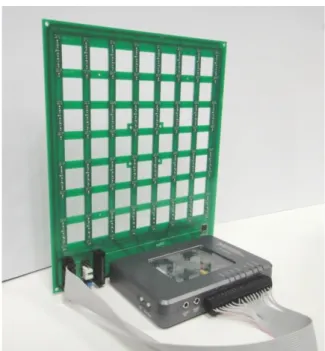
The acoustic images acquisition system used in this paper is based on a Uniform Planar Array (UPA) of MEMS microphones. This array, which has been entirely developed by the authors, is a square array of 64 (8 × 8) MEMS microphones that are spaced uniformly, every 2.125 cm, in a rec-tangular Printed Circuit Board (PCB), as shown in Figure 1.
This array was designed to work in an acoustic frequency range between 4 and 16 kHz. The 2.125 cm spacing corresponds to λ/2 for the 8 kHz frequency. This spacing allows a good resolution for low frequencies, while avoiding grating lobes for high frequencies in the angular exploration zone of interest.
Figure 1. Array module with myRIO and MEMS array board.
A MyRIO platform [9] is the base unit for this system. This platform belongs to the Reconfigu-rable Input-Output (RIO) family of devices from National Instruments, that is oriented to sensors with nonstandard acquisition procedures. The embedded processor included in myRIO is capable of running all the software algorithms to generate acoustic images, so it can be used as a standalone array module formed by a myRIO connected to a MEMS array board as shown in Figure 1. Alt-hough myRIO can work as a standalone system, the lack of display means that it is usually con-trolled from a PC connected using a Wi-Fi interface. In a global hardware setup, as shown in Figure 2, the system includes a PC and one or more array modules.
Figure 2. Global hardware setup.
The algorithms implemented in the system, shown in Figure 3, can be divided into three blocks: MEMS acquisition, signal processing, and image generation (wideband beamforming and image storage). The programming language used is LabVIEW 2015, along with its Real Time, FPGA, and GPU modules, which allows developing applications on different hardware platforms like those used in the system: FPGA, Embedded Processor (EP), PC, and GPU.
In the acquisition block, each MEMS microphone with a PDM interface performs signal acquisition.
Finally, in the image generation block, based on wideband beamforming, a set of N × N steering directions are defined, and the beamformer output are assessed for each of these steering directions. The images generated are then displayed and stored in the system. A processing platform enabled to work at a low level -to acquire signals- and at a high level -to implement spatial processing algorithms-, using low cost commercial systems, was defined. The processing algorithms are shared between the FPGA and the PC, excluding beamforming, which is implemented on the GPU, as shown in Figure 3. The embedded processor is used to control and transfer data between the PC and FPGA.
Figure 3. System framework
2.2 Positioning system
The array module is moved in space with a cartesian positioning system, capable of positioning the array inside a cubic volume of 1500x1500x1500 mm3 with repeatability accuracy of 0.02 mm in each of the three spatial dimensions. It is shown in Figure 4. While it is a 3D positioner, only 2 di-mensions are being used in this application.
Figure 4. 3D positioning system
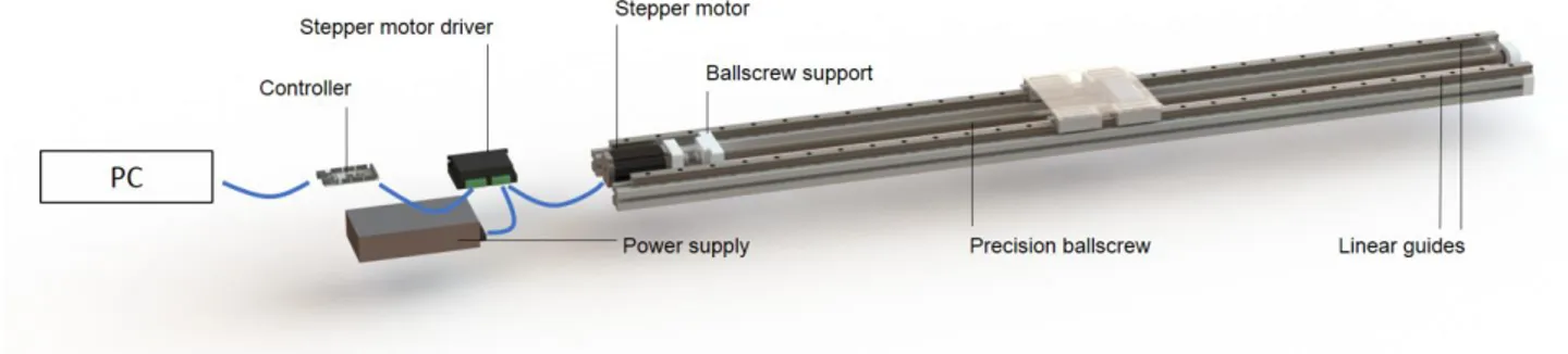
simulat-went through several refinement iterations until finally built. The design puts together several linear actuators in a solid aluminum frame. A diagram of the main components in a single axis actuator can be seen in Figure 5.
Each linear actuator is powered by one 24V stepper motor, there are 4 in total.
Precision preloaded ball-screws convert circular motion from the motor to linear motion with no backlash.
Linear guides limit the motion from the ball-screw to a specific line.
High density aluminum profiles, for improved stiffness, support the other components and ensure perpendicularity of the axes is maintained in the complete working volume. Specific parts like end-stop switch supports, motor supports, and ball-screw supports
were machined in polyacetal, an engineering plastic known for high stiffness, good di-mensional stability and good machinability.
Figure 5. Linear actuator schematic
3. Virtual array
The explained 8x8 planar array of MEMS microphones [8] is placed on a 2D positioning system, as can be observed in Figure 4. The position of this array is changed on the vertical and horizontal directions, in 20 cm steps (the spatial aperture of the array, in both directions, vertical and horizon-tal), moving on a surface that is parallel to the array itself. The array obtains an acoustic image of the target under test in each of these positions.
The data acquired by the 8x8 array in each of the positions are added in a data structure, equiva-lent to what would be obtained with an array of hundreds of sensors. From this data, the spatial pro-cessing is performed using a beamforming algorithm, to obtain the high resolution acoustic images. Two virtual arrays have been developed: a 3x3 virtual array (moving the single array on a grid of 3x3 positions, simulating an array of 24x24 microphones) and a 5x5 virtual array (moving the sin-gle array on a grid of 5x5 positions, simulating an array of 40x40 microphones). Table 1 shows the characteristics of these virtual arrays.
Table 1: Virtual array characteristics
Virtual array Number of sensors Area Dimensions
3x3 576 0.36 m2 60 cm x 60 cm
9x9 1600 1.0 m2 100 cm x 100 cm
Afterwards, these virtual arrays have been used to obtain acoustic images of two different targets placed opposite the array:
- On one hand, a working reference loudspeaker. The sound that the loudspeaker generates is received by the MEMS microphones of the array.
In both case, the signal that is received by the array microphones is used, afterwards, to obtain the acoustic images of the target.
3.1 Case study 1: Loudspeaker
In the first case study, the acoustic image of a reference loudspeaker is analyzed. The loudspeak-er is placed 150 cm opposite the virtual array, on the broadside, i.e. placed at 0o in both, azimuth and elevation coordinates. Figure 6 shows the obtained acoustic images using a single array and 3x3 and 5x5 virtual arrays, with a working frequency of 5 kHz.
(a) Single array
(b) 3x3 virtual array (c) 5x5 virtual array
Figure 6. Acoustic images of the reference loudspeaker
It can be observed how the main lobe width decreases proportionally with the increment of the virtual number of sensors of the array in each dimension. It can also be observed that there isn’t grating lobes in beampattern.
3.2 Case study 1: Person
Figure 7. Person under test
Figure 8 shows the acoustic images, obtained for this study case, using a single array and 3x3 and 5x5 virtual arrays, with a working frequency of 11 kHz
(a) Single array
(b) 3x3 virtual array (c) 5x5 virtual array
Figure 8. Acoustic images of a person
identifi-cation biometric systems with low error rates, by means of using classifiers based on machine learn-ing.
4. Conclusions
Virtual arrays have been developed moving a single 8x8 planar array of MEMS microphones on a grid of n x n positions, simulating an array of (n*8) x (n*8) microphones. The single array is placed on a 2D positioning system, and its position is changed on the vertical and horizontal direc-tions, in steps of a distance equal to the array spatial aperture. The array obtains an acoustic image of the target under test in each of these positions, and they are added in a data structure equivalent to the obtained with a high resolution array.
The developed virtual arrays have been tested by using them to obtain acoustic images of two different targets placed opposite the array: a working reference loudspeaker and a person. In the first case the system works as a passive system, it only “listen”, i.e. the microphone array receives the loudspeaker sound signal; in the second case the system is active, a sound signal is generated to be reflected over the person under test, and after that the reflected signal is received by the MEMS microphones of the array.
It both cases it be observed how the main lobe width decreases proportionally with the increment of the virtual number of sensors of the array in each dimension, without the presence of grating lobes. The increment of the spatial resolution with a virtual array allows obtaining high resolution acoustic images.
Acknowledgements
This work has been funded by the Spanish research project SAM (MINECO: TEC 2015-68170-R).
REFERENCES
1 Van Trees, H. Optimum Array Processing: Part IV of Detection, Estimation and Modulation Theory, John Wiley & Sons: New York, USA (2002).
2 Brandstein M.; Ward D., Microphone arrays, Springer: New York, USA (2001).
3 Van Veen, B.D.; Buckley K.M. Beamforming: A Versatile Approach to Spatial Filtering. IEEE ASSP Magazine, 1988, 4-24, (1988).
4 Beeby, S. et al. MEMS Mechanical Sensors; Artech House Publishers: Norwood, MA, USA (2004).
5 Scheeper, P.R. et al. A review of silicon microphones, Sens Actuat A Phys, 44 (1), 1-11, (1994).
6 Siong Gan W., Acoustic Imaging: Techniques and Applications for Engineers, John Wiley & Sons: New York, USA (2012).
7 Ravetta, P., Muract, J. and Burdisso, R., Feasibility study of microphone phased array based machinery health monitoring. Mecánica Computacional, 26, 23-37, (2007).
8 Izquierdo, A. et al. Design and Evaluation of a Scalable and Reconfigurable Multi-Platform System for Acoustic Imaging. Sensors, 16 (10), 1671, (2016).