Generation of ferromagnetism on non-magnetic materials
178
0
0
Texto completo
(2) Els Doctors Josep Nogués Sanmiquel i Jordi Sort Viñas, directors de la Tesi Doctoral “Generation of ferromagnetism on non-magnetic materials” realitzada per l’Enric Menéndez Dalmau,. fan constar que l’aportació de l’Enric Menéndez Dalmau al treball que es presenta ha estat fonamental tant pel que fa al disseny experimental, com per a l’obtenció de les mostres, la realització dels experiments, l’anàlisi de les dades i la discussió i elaboració dels resultats.. I per a què així consti, a petició de l’interessat i als efectes oportuns, signem la tesi doctoral a Bellaterra, el 25 de Setembre de 2008.. Dr. J. Nogués. Dr. J. Sort.
(3) Acknowledgements En primer lloc, voldria agrair la permanent dedicació, suport i orientació científica que he rebut per part dels meus directors, el Dr. Jordi Sort i el Prof. Josep Nogués. Agraeixo la seva crítica i els consells que m’han donat en tot moment, el temps que han invertit en la meva formació científica i, en particular, el fet que han aconseguit fer-me sentir un investigador més al seu costat.. Agraeixo a la Professora Maria Dolors Baró i al Prof. Santiago Suriñach la possibilitat que em van donar de pertànyer al Grup de Física de Materials II, la seva ajuda constant i els seus consells.. Voldria agrair al Servei de Microscòpia de la UAB i al Dr. Ángel Álvarez la seva col·laboració i consell en la realització i anàlisi de les experiències de microscòpia electrònica i difracció de raigs X, respectivament. A més, també voldria destacar la total disposició del Jordi, el Manel, el Rafa i el Ramón pel suport tècnic que donen al nostre grup.. Un record especial per a la resta de membres, amb els que he compartit moments molt bons i he après un munt de coses, que pertanyen o han format part del Grup de Física de Materials II.. En relació a les meves estades al Forschungszentrum Dresden-Rossendorf d’Alemanya, voldria destacar la bona acollida, el tracte i l’ajut que he rebut del Dr. Maciej Oskar Liedke i del Dr. Jürgen Fassbender. També voldria donar les gràcies a la resta de persones amb les que he treballat al llarg d’aquests anys i la seva col·laboració s’ha vist directament reflectida en aquesta Tesi: Dr. A. Concustell, A. Martinavicius, Dr. G. Abrasonis, T. Strache, Prof. W. Möller, Dr. T. Gemming, Dra. A. Weber, Dra. L. J. Heyderman, Prof. K. V. Rao, Dr. S. C. Deevi, J. Sommerlatte i Prof. K. Nielsch.. Vull agrair al Ministerio de Educación y Ciencia per la beca de Formación de Personal Investigador, cofinançada pel Fons Social Europeu, que em van concedir..
(4) També vull donar les gràcies als meus amics per les bones estones que passo al seu costat i els ànims que sempre m’han donat. Finalment i de manera molt especial, m’agradaria agrair el constant suport i ajuda que sempre he rebut i rebo dels meus pares, de la meva germana Mireia i dels meus cosins, un pilar fonamental per a mi..
(5) Resum En els darrers anys, el desenvolupament de nous mètodes per a la fabricació de xarxes ordenades de nanoestructures magnètiques (litografia magnètica) ha esdevingut un camp de recerca de gran interès. Això es deu tant per l’ampli ventall d’aplicacions tecnològiques que se’n deriven de les estructures magnètiques de grandària submicromètrica (biomedicina, gravació magnètica, ...), com per raons de caire més fonamental, ja que sovint el comportament magnètic d’aquests materials a escala nanomètrica és diferent del corresponent als materials massissos. Els aliatges de Fe60Al40 (percentatge atòmic) i els acers inoxidables austenítics posseeixen una combinació de propietats estructurals i magnètiques que els converteix en materials amb cert potencial per a ser litografiats magnèticament. Des d’un punt de vista magnètic, mentre que els aliatges de Fe60Al40 ordenats atòmicament són paramagnètics a temperatura ambient, els aliatges de Fe60Al40 desordenats a nivell atòmic presenten un comportament ferromagnètic. Pel que fa als acers inoxidables austenítics, a partir de deformació mecànica, es pot induir la transformació en estat sòlid de la fase austenita (paramagnètica) a la fase martensita (ferromagnètica) en aquests aliatges ferris. A més, els processos de nitruració a temperatura moderada en acers inoxidables austenítics permeten transformar parcialment la fase austenita en la fase “austenita expandida”, que és una solució sòlida sobresaturada de nitrogen que presenta un comportament ferromagnètic. Aquesta Tesi està basada en la generació de xarxes ordenades d’entitats ferromagnètiques a escala micro/nanomètrica, dins d’una matriu paramagnètica, en la superfície d’aliatges de Fe60Al40 i acers inoxidables austenítics. Aquest propòsit s’assoleix aprofitant les transicions magnètiques que tenen lloc en aquests materials després de sotmetre’ls a processos de deformació plàstica local (nanoindentació) i irradiació controlada amb ions (ús de feixos d’ions focalitzats i irradiació amb ions de gasos nobles a través de màscares en el cas del Fe60Al40 i processos de nitruració a través de màscares d’irradiació en els acers inoxidables austenítics). Cal esmentar que també s’ha dut a terme un estudi detallat de les modificacions a nivell estructural, mecànic i magnètic que ocorren en aquests materials una vegada s’han deformat mecànicament o irradiat amb ions..
(6) Summary In recent years, intense research is being pursued in the development of novel methods for the fabrication of arrays of ordered magnetic nanostructures. This is motivated, in part, by the technological applications of sub-micron magnetic structures, ranging from biomedicine to recording media, but it is also due to fundamental scientific reasons, since the behavior of magnetic materials at this length scale is often significantly different from that in the bulk. Fe60Al40 (at. %) alloys and austenitic stainless steels show an interesting combination of magnetic and structural properties, which makes them turn into potential candidates to be magnetically patterned. Namely, from the magnetic point of view, whereas atomically ordered Fe60Al40 (at. %) is paramagnetic at room temperature, disordered Fe60Al40 becomes ferromagnetic. Concerning austenitic stainless steels, due to mechanical deformation, a phase transformation from the paramagnetic austenite phase to the ferromagnetic martensite phase can occur in these ferrous alloys. In addition, nitriding of austenitic stainless steels at moderate temperatures is able to partially transform the austenite phase into the supersaturated nitrogen solid solution, often called in the literature “expanded austenite” phase, which shows ferromagnetic behavior. This Thesis is mainly focused on the generation of ordered arrays of micro/nanoscaled ferromagnetic entities (i.e., magnetic patterning), embedded in a paramagnetic matrix, at the surface of either Fe60Al40 (at. %) alloys or austenitic stainless steels. This is accomplished by taking advantage of the magnetic transitions which occur in these alloys upon local plastic deformation (nanoindentation) and controlled ion irradiation (focused ion beam and broad beam noble gas ion irradiation through shadow masks in FeAl alloys and ion beam nitriding through shadow masks in austenitic stainless steels). Furthermore, a detailed study of the structural, mechanical and magnetic changes which take place in these materials upon either mechanical deformation or ion irradiation is presented..
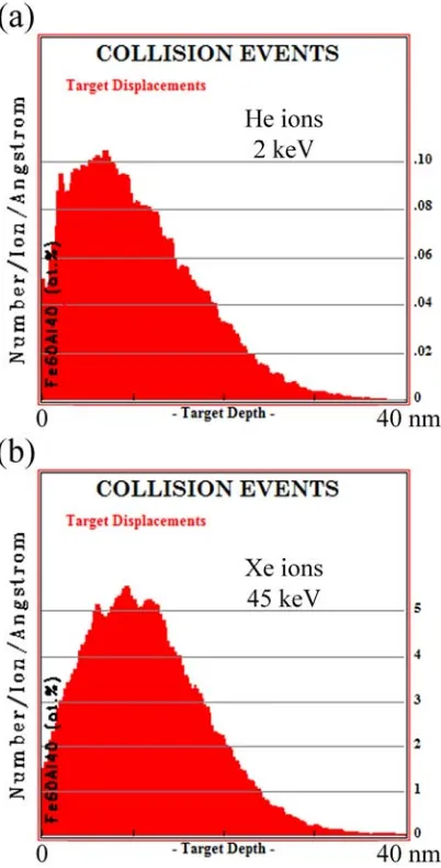
(7) Index. Index Preface. 1. References. 8. 1. Introduction. 9. 1.1. Patterning magnetic structures. 9. 1.1.1. Using templates or masks. 9. 1.1.2. Direct methods. 15. 1.2. Local control of magnetic properties by ion irradiation. 16. 1.3. Induced magnetism in non-magnetic alloys. 17. 1.3.1. Ferromagnetism induced by atomic disordering in Fe60Al40 (at. %) alloys. 17. 1.3.2. Ferromagnetism induced by structural phase transformations in austenitic stainless steels. 19. References. 21. 2. Experimental methods. 27. 2.1. Processing methods. 28. 2.1.1. Mechanical milling. 28. 2.1.1.1. Fundamentals. 28. 2.1.1.2. Milling parameters. 29. 2.1.1.2.1. Intensity (transferred power). 30. 2.1.1.2.2. Milling atmosphere. 30. 2.1.1.2.3. Milling media. 31. 2.1.1.2.4. Milling temperature. 31. 2.1.1.3. Temporal evolution of the microstructure. 32. 2.1.1.4. Working conditions. 33. 2.1.2. Uniaxial compression testing 2.1.2.1. Working conditions 2.2. Irradiation methods 2.2.1. Broad beam ion irradiation 2.2.1.1. Essentials on ion-solid interactions. 33 34 34 35 35. 2.2.1.1.1. Mechanisms of energy loss. 37. 2.2.1.1.2. Radiation damage. 38. 2.2.1.1.3. Radiation damage estimation by means of ion-solid simulations: the TRIM program. 42. 2.2.1.1.4. Radiation sputtering and ion implantation. 43. 2.2.1.2. Noble gas ion irradiation. 44. 2.2.1.2.1. Ion implanter. 45. 2.2.1.2.2. Working conditions. 46.
(8) Index. 2.2.1.3. Ion beam nitriding 2.2.3. Focused ion beam 2.2.3.1. Working conditions 2.2.4. Electron beam lithography 2.2.4.1. Working conditions 2.3. Structural, morphological and mechanical characterization techniques. 48 50 52 52 53 53. 2.3.1. X-ray diffraction. 54. 2.3.1.1. Fundamentals. 54. 2.3.1.2. Modes of structure analysis. 56. 2.3.1.2.1. Bragg diffractometer. 56. 2.3.1.2.2. Glancing incidence. 57. 2.3.1.3. X-ray penetration depth. 58. 2.3.1.4. The long-range order parameter. 60. 2.3.1.5. The Rietveld refinement using the MAUD program. 62. 2.3.1.6. Working conditions. 63. 2.3.1.6.1. X-ray penetration depth in Fe60Al40 (at. %) alloys. 64. 2.3.1.6.2. X-ray penetration depth in AISI 316L ASS. 65. 2.3.2. Nuclear reaction analysis. 65. 2.3.3. Scanning electron microscopy. 66. 2.3.3.1. Interaction between the electron beam and the sample. 67. 2.3.3.2. Working conditions. 69. 2.3.4. Atomic force microscopy. 69. 2.3.5. Vickers macro/microindentation. 72. 2.3.5.1. Fundamentals. 72. 2.3.5.2. Working conditions. 74. 2.3.6. Nanoindentation 2.3.6.1. Working conditions. 74 77. 2.4. Magnetic characterization techniques. 77. 2.4.1. Vibrating sample magnetometry. 77. 2.4.1.1. Fundamentals. 78. 2.4.1.2. Working conditions. 79. 2.4.2. Magneto-optical Kerr effect. 80. 2.4.2.1. Magneto-optical Kerr effect setup. 81. 2.4.2.2. Working conditions. 81. 2.4.3. Magnetic force microscopy 2.4.3.1. Working conditions. 82 83. References. 84. 3. Results and discussion. 89.
(9) Index. 3.1. Fe60Al40 (at. %) alloys 3.1.A. Ferromagnetism induced by mechanical deformation 3.1.A.1. Macroscopic approach: compression tests. 90 90 90. 3.1.A.1.1. Experimental details. 90. 3.1.A.1.2. Structural characterization. 91. 3.1.A.1.3. Magnetic characterization. 94. 3.1.A.1.4. Mechanical hardness characterization. 97. 3.1.A.2. Micro and nanoscaled approaches: nanoindentation. 98. 3.1.A.2.1. Experimental details. 99. 3.1.A.2.2. Magnetic patterning. 99. 3.1.B. Ferromagnetism induced by ion irradiation 3.1.B.1. Macroscopic approach: broad beam irradiation. 105 105. 3.1.B.1.1. Experimental details. 105. 3.1.B.1.2. Magnetic and structural characterization. 106. 3.1.B.2. Micro and nanoscaled approaches: lithography through shadow masks 111 3.1.B.2.1. Broad beam irradiation through TEM grids. 111. 3.1.B.2.1.1. Experimental details. 111. 3.1.B.2.1.2. Magnetic patterning. 111. 3.1.B.2.2. Broad beam irradiation through alumina masks. 113. 3.1.B.2.2.1. Experimental details. 113. 3.1.B.2.2.2. Magnetic patterning. 114. 3.1.B.2.3. Broad beam irradiation through electron beam lithographed specimens. 115. 3.1.B.2.3.1. Experimental details. 115. 3.1.B.2.3.2. Magnetic patterning. 115. 3.1.B.2.4. Local irradiation by focused ion beam. 120. 3.1.B.2.4.1. Experimental details. 120. 3.1.B.2.4.2. Magnetic patterning. 121. 3.2. Austenitic stainless steels 3.2.A. Ferromagnetism induced by mechanical deformation 3.2.A.1. Macroscopic approach: ball milling and compression tests. 125 125 125. 3.2.A.1.1. Experimental details. 125. 3.2.A.1.2. Ball milling of AISI 316L powders (dynamic approach). 127. 3.2.A.1.2.1. Structural and morphological characterization. 127. 3.2.A.1.2.2. Magnetic characterization. 130. 3.2.A.1.3. Uniaxial compression of bulk AISI 316L specimens (quasi-static approach) 3.2.A.1.3.1. Structural characterization. 132 132.
(10) Index. 3.2.A.1.3.2. Magnetic characterization. 134. 3.2.A.1.3.3. Mechanical hardness characterization. 135. 3.2.A.1.4. Mechanisms of the strain-induced transformation: static vs. dynamic approaches 3.2.A.2. Micro and nanoscaled approaches: nanoindentation. 136 139. 3.2.A.2.1. Experimental details. 139. 3.2.A.2.2. Magnetic patterning. 140. 3.2.B. Ferromagnetism induced by ion irradiation 3.2.B.1. Macroscopic approach: broad beam ion beam nitriding. 144 144. 3.2.B.1.1. Experimental details. 144. 3.2.B.1.2. Structural and magnetic characterization. 145. 3.2.B.2. Micro and nanoscaled approaches: lithography through shadow masks 150 3.2.B.2.1. Broad beam ion beam nitriding through TEM grids. 150. 3.2.B.2.1.1. Experimental details. 150. 3.2.B.2.1.2. Magnetic patterning. 150. 3.2.B.2.2. Broad beam ion beam nitriding through alumina masks. 153. 3.2.B.2.2.1. Experimental details. 153. 3.2.B.2.2.2. Magnetic patterning. 153. References. 156. 4. Conclusions. 161. 4.1. Fe60Al40 (at. %) alloys 4.1.A. Ferromagnetism induced by mechanical deformation. 161 161. 4.1.A.1. Macroscopic approach: compression tests. 161. 4.1.A.2. Micro and nanoscaled approaches: nanoindentation. 162. 4.1.B. Ferromagnetism induced by ion irradiation 4.1.B.1. Macroscopic approach: broad beam irradiation. 162 162. 4.1.B.2. Micro and nanoscaled approaches: lithography through shadow masks and focused ion beam 4.2. Austenitic stainless steels 4.2.A. Ferromagnetism induced by mechanical deformation. 162 164 164. 4.2.A.1. Macroscopic approach: ball milling and compression tests. 164. 4.2.A.2. Micro and nanoscaled approaches: nanoindentation. 164. 4.2.B. Ferromagnetism induced by ion irradiation 4.2.B.1. Macroscopic approach: broad beam ion beam nitriding. 165 165. 4.2.B.2. Micro and nanoscaled approaches: lithography through shadow masks 165 Appendix. 167.
(11) Preface. Preface In recent years, intense research is being pursued in the development of novel methods for the fabrication of arrays of ordered magnetic nanostructures [1,2]. This is motivated, in part, by the technological applications of sub-micron magnetic structures, ranging from biomedicine to recording media [3,4], but it is also due to fundamental scientific reasons, since the behavior of magnetic materials at this length scale is often significantly different from that in the bulk [5]. Nevertheless, the production of magnetic nanostructures, arranged in regular configurations (i.e., patterned), over areas in the macroscopic range still remains rather challenging [2].. Fe60Al40 (at. %) alloys and austenitic stainless steels (ASSs) show an interesting combination of magnetic and structural properties, which make them turn into potential candidates to be magnetically patterned. Namely, from the magnetic point of view, whereas atomically ordered Fe60Al40 (at. %) is paramagnetic at room temperature, disordered Fe60Al40 becomes ferromagnetic [6,7]. Concerning ASSs, it is known that, due to mechanical deformation, a phase transformation from the paramagnetic austenite (γ) phase to the ferromagnetic martensite (α′) phase can occur in these ferrous alloys [8]. In addition, nitriding of ASSs at moderate temperatures is able to partially transform the austenite phase into the supersaturated nitrogen solid solution, often called in the literature “expanded austenite” or γN phase [9], which shows ferromagnetic behavior [10].. This Thesis is mainly focused on the generation of ordered arrays of micro/nanoscaled ferromagnetic entities (i.e., magnetic patterning) at the surface of either Fe60Al40 (at. %) alloys or ASSs (AISI 304L, AISI 316 and AISI 316L, see appendix for further details). This is accomplished by taking advantage of the magnetic transitions which occur in these alloys upon local plastic deformation and controlled ion irradiation.. 1.
(12) Preface. The main objectives of this doctoral thesis are:. - To investigate the deformation-induced ferromagnetism in atomically ordered Fe60Al40 (at. %) alloys subjected to compression tests and correlate structural (i.e., lattice cell parameter, crystallite size, microstrain and atomic intermixing), mechanical (i.e., microhardness) and magnetic (i.e., saturation magnetization) properties.. - To study the generation of ferromagnetism in ordered Fe60Al40 (at. %) alloys by ion irradiation, analyzing the effect of different ion species on the induced magnetism.. - To show the feasibility to produce periodic arrays of isolated ferromagnetic structures in the micro/nanoscaled range, embedded in a paramagnetic matrix, by means of either local mechanical deformation (i.e., nanoindentation) or selective ion irradiation (i.e., using either ion irradiation through shadow masks or focused ion beam) on Fe60Al40 alloys.. - To study the mechanically induced martensitic transformation obtained by means of either ball milling processes in AISI 316L ASS powders (dynamic approach, i.e. high strain rate processing) or compressive deformation in AISI 316L ASS bulk specimens (quasi-static approach, i.e. low strain rate processing), aimed at tailoring and correlating the induced structural, mechanical, and magnetic properties.. - To demonstrate the feasibility to produce periodic arrays of isolated ferromagnetic structures in the micro/nanoscaled range, embedded in a paramagnetic matrix, by either local mechanical deformation (i.e., nanoindentation) or selective ion irradiation (i.e., ion beam nitriding through shadow masks) on austenitic stainless steels.. 2.
(13) Preface. This work has been organized in different chapters as follows:. - Chapter 1 introduces some of the current techniques to prepare arrays of ordered magnetic structures. Moreover, the fundamental aspects regarding the origin of ferromagnetism in both Fe60Al40 (at. %) alloys and ASSs are presented.. - Chapter 2 deals with the experimental procedures that have been used to induce ferromagnetism in Fe60Al40 (at. %) alloys and austenitic stainless steels by means of either plastic deformation (mechanical milling and compression testing) or ion irradiation (broad beam ion irradiation and focused ion beam). Next, the techniques for structural, morphological, mechanical and magnetic characterization are described.. - Chapter 3 presents the obtained results and their discussion. The studied materials (i.e., Fe60Al40 and ASSs) lead to the two major sections of this chapter. Both sections start reporting on the generation of ferromagnetism by mechanical deformation (part A) in a macroscopic approach. Then, the results concerning the creation of micro/nanoscaled ferromagnetic structures by means of local mechanical deformation are presented. Finally, the irradiation-induced ferromagnetism investigation (part B) is reported starting from the macroscopic approach, followed by the magnetic patterning using ion irradiation.. - Chapter 4 points out the main conclusions of this doctoral thesis.. Finally, an appendix about some compositional aspects of the studied ASSs is presented.. 3.
(14) Preface. This Thesis has been partially based on the following articles: - J. Sort, A. Concustell, E. Menéndez, S. Suriñach, M. D. Baró, J. Farran and J. Nogués: Selective generation of local ferromagnetism in austenitic stainless steel using nanoindentation Appl. Phys. Lett. 89 032509 (2006) - J. Sort, A. Concustell, E. Menéndez, S. Suriñach, K. V. Rao, S. C. Deevi, M. D. Baró and J. Nogués: Periodic arrays of micrometer and sub-micrometer magnetic structures prepared by nanoindentation of a nonmagnetic intermetallic compound Adv. Mater. 18 1717 (2006) - J. Fassbender, M. O. Liedke, T. Strache, W. Möller, E. Menéndez , J. Sort, K. V. Rao, S. C. Deevi and J. Nogués: Ion mass dependence of the irradiation-induced local creation of ferromagnetism in Fe60Al40 alloys Phys. Rev. B 77 174430 (2008) - E. Menéndez, A. Martinavicius, M. O. Liedke, G. Abrasonis, J. Fassbender, J. Sommerlatte, K. Nielsch, S. Suriñach, M. D. Baró, J. Nogués and J. Sort: Patterning of magnetic structures on austenitic stainless steel by local ion beam nitriding Acta Mater. 56 4570 (2008) - E. Menéndez, J. Sort, M. O. Liedke, J. Fassbender, S. Suriñach, M. D. Baró and J. Nogués: Two-fold origin of the deformation-induced ferromagnetism in bulk Fe60Al40 (at.%) alloys New J. Phys. 10 103030 (2008) - J. Sort, E. Menéndez, A. Concustell, S. Suriñach, M. D. Baró, G. Salazar-Alvarez and J. Nogués: Nous materials per a l’emmagatzematge magnètic d’alta densitat Revista de l’Institut d’Estudis Catalans In press - E. Menéndez, J. Sort, M. O. Liedke, J. Fassbender, T. Gemming, A. Weber, L. J. Heyderman, S. Suriñach, K. V. Rao, S. C. Deevi, M. D. Baró and J. Nogués: Direct magnetic patterning due to the generation of ferromagnetism by selective ion irradiation of paramagnetic FeAl alloys Small doi: 10.1002/smll.200800783 In press - E. Menéndez, J. Sort, M. O. Liedke, J. Fassbender, S. Suriñach, M. D. Baró and J. Nogués: Controlled generation of ferromagnetic martensite from paramagnetic austenite in AISI 316L austenitic stainless steel submitted. 4.
(15) Preface. and the patent P200600426: - Inventors (in order of authorship): J. Sort, J. Nogués, A. Concustell, E. Menéndez, S. Suriñach and M. D. Baró. Title: Procedimiento para la fabricación de un artículo con zonas ferromagnéticas y zonas no ferromagnéticas (Priority Country: Spain, Priority Date:. 17th. February. 2006,. Holder. Entities:. Universitat. Autònoma. de. Barcelona/Institució Catalana de Recerca i Estudis Avançats). Other articles co-authored by E. Menéndez not directly related to this Thesis are: - E. Menéndez, J. Sort, V. Langlais, A. Zhilyaev, J. S. Muñoz, S. Suriñach, J. Nogués and M. D. Baró: Cold compaction of metal-ceramic (ferromagnetic-antiferromagnetic) composites using high pressure torsion J. Alloys Compd. 434-435 505 (2007) - E. Menéndez, J. Sort, A. Concustell, S. Suriñach, J. Nogués and M. D. Baró: Microstructural evolution during solid state sintering of ball-milled nanocomposite WC10 mass% Co powders Nanotechnology 18 185609 (2007) - E. Menéndez, J. Sort, S. Suriñach, M. D. Baró and J. Nogués: Tailoring deformationinduced effects in Co powders by milling them with α-Al2O3 J. Mater. Res. 22 2998 (2007) - J. Sort, K. S. Buchanan, J. E. Pearson, A. Hoffmann, E. Menéndez, G. SalazarAlvarez, M. D. Baró, M. Miron, B. Rodmacq, B. Dieny and J. Nogués: Tailoring the magnetization reversal of elliptical dots using exchange bias J. Appl. Phys. 103 07C109 (2008) - E. Menéndez, G. Salazar-Alvarez, A. P. Zhilyaev, S. Suriñach, M. D. Baró, J. Nogués and J. Sort: Cold consolidation of metal-ceramic nanocomposite powders with large ceramic fractions Adv. Funct. Mater. 18 3293 (2008). Part of this work has been presented in the following Invited Talks which have been given in international conferences: - J. Sort, A. Concustell, E. Menéndez, S. Suriñach, K. V. Rao, S. C. Deevi, J. Nogués and M. D. Baró: Periodic arrays of micron and submicron magnetic structures prepared. 5.
(16) Preface. by nanoindentation of a non-magnetic intermetallic compound III Workshop on Metastable and Nanostructured Materials (Nanomat 2006) Rio de Janeiro (Brazil) June 5 – 8 2006 - J. Sort, A. Concustell, E. Menéndez, S. Suriñach, K. V. Rao, J. Farran, S. C. Deevi, J. Nogués and M. D. Baró: Arrays of micron and submicron magnetic structures prepared by nanoindentation of non-magnetic substrates International Symposium on Metastable, Mechanically Alloyed and Nanocrystalline Materials (ISMANAM 2006) Warsaw (Poland) August 27 – 31 2006 - J. Sort, E. Menéndez, M. O. Leidke. T. Strache, J. Fassbender, T. Gemming, A. Weber, L. J. Heyderman, S. Suriñach, A. Concustell, K. V. Rao, S. C. Deevi, M. D. Baró and J. Nogués: Micro- and nanoscale patterning of paramagnetic FeAl alloys by means. of. nanoindentation. or selective ion. irradiation First. workshop on. nanolithography and their applications Zaragoza (Spain) October 23 – 26 2007 - J. Sort, E. Menéndez, A. Concustell, S. Suriñach, M. D. Baró, G. Salazar-Alvarez and J. Nogués: Nous materials per a l’emmagatzematge magnètic d’alta densitat Jornada sobre nanociència i nanotecnologia a l’Institut d’Estudis Catalans Barcelona (Spain) November 30 2007 - E. Menéndez, J. Sort, M. O. Liedke, J. Fassbender, T. Gemming, A. Weber, L. J. Heyderman, S. Suriñach, A. Concustell, K. V. Rao, S. C. Deevi, M. D. Baró and J. Nogués: Micro-/nano-scale magnetic patterning of paramagnetic FeAl intermetallic alloys Winter School – Women in Nano Kranjska Gora (Slovenia) February 7 – 9 2008 - J. Sort, E. Menéndez, M. O. Liedke, T. Strache, J. Fassbender, W. Möller, T. Gemming, A. Weber, L. J. Heyderman, S. Suriñach, K. V. Rao, S. C. Deevi, M. D. Baró and J. Nogués: Magnetic lithography on paramagnetic FeAl alloys by selective ion irradiation 9th International Conference on Nanostructured Materials (NANO2008) Rio de Janeiro (Brazil) June 1 – 6 2008 - E. Menéndez, M. O. Liedke, A. Martinavicius, G. Abrasonis, T. Strache, W. Möller, J. Fassbender, T. Gemming, J. Sommerlatte, K. Nielsch, S. C. Deevi, K. V. Rao, J. Sort, S. Suriñach, M. D. Baró and J. Nogués: Ion beam irradiation to locally generate ferromagnetism in non-magnetic intermetallic alloys and non-magnetic austenitic. 6.
(17) Preface. stainless steels 2nd Meeting of the User Selection Panel and User Meeting Forschungszentrum Dresden-Rossendorf (Germany) July 6 – 7 2008 - E. Menéndez, J. Sort, M. O. Liedke, T. Strache, J. Fassbender, W. Möller, T. Gemming, A. Weber, L. J. Heyderman, S. Suriñach, S. C. Deevi, K. V. Rao, J. Sommerlatte, K. Nielsch, J. Nogués and M. D. Baró: Magnetic nanoscale lithography on FeAl alloys by means of ion irradiation International Symposium on Metastable, Mechanically Alloyed and Nanocrystalline Materials (ISMANAM 2008) Buenos Aires (Argentina) July 6 – 10 2008 - E. Menéndez, J. Sort, M. O. Liedke, T. Strache, J. Fassbender, W. Möller, T. Gemming, A. Weber, L. J. Heyderman, S. Suriñach, S. C. Deevi, K. V. Rao, J. Sommerlatte, K. Nielsch, M. D. Baró and J. Nogués: Generation of Micro/Nano-scaled ferromagnetic entities by selective ion irradiation on FeAl alloys 16th International Conference on Ion Beam Modification of Materials Dresden (Germany) August 31 – September 5 2008 - E. Menéndez, J. Sort, M.O. Liedke, T. Strache, J. Fassbender, W. Möller, T. Gemming, A. Weber, L. J. Heyderman, S. Suriñach, S. C. Deevi, K. V. Rao , J. Sommerlatte, K. Nielsch, M. D. Baró and J. Nogués: Direct nanoscale magnetic patterning in FeAl alloys by means of ion irradiation 9th Trends in Nanotechnology International Conference (TNT) Oviedo (Spain) September 1 – 5 2008. 7.
(18) Preface. References. [1] J. I. Martín, J. Nogués, K. Liu, J. L. Vicent and I. K. Schuller J. Magn. Magn. Mater. 256 449 (2003) [2] A. O. Adeyeye and N. Singh J. Phys. D: Appl. Phys. 41 153001 (2008) [3] S. S. P. Parkin, X. Jiang, C. Kaiser, A. Panchula, K. Roche and M. Samant Proc. IEEE 91 661 (2003) [4] C. A. Ross Annu. Rev. Mater. Res. 31 203 (2001) [5] R. Skomski J. Phys.: Condens. Mater. 15 R841 (2003) [6] M. J. Besnus, A. Herr and A. J. P. Meyer J. Phys. F: Met. Phys. 5 2138 (1975) [7] E. P. Yelsukov, E. V. Voronina and V. A. Barinov J. Magn. Magn. Mater. 115 271 (1992) [8] S. S. Hecker, M. G. Stout, K. P. Staudhammer and J. L. Smith Metall. Trans. A 13 619 (1982) [9] M. P. Fewell, D. R. G. Mitchell, J. M. Priest, K. T. Short and G. A. Collins Surf. Coat. Technol. 131 300 (2000) [10] O. Öztürk and D. L. Williamson J. Appl. Phys. 77 3839 (1995). 8.
(19) Introduction. 1. Introduction The most widely used fabrication methods for magnetic nanostructure production will be briefly described in this chapter. Then, the origin of ferromagnetism in paramagnetic Fe60Al40 (at. %) alloys and austenitic stainless steels (ASSs) will be addressed.. 1.1. Patterning magnetic structures In this subchapter, the main conventional techniques for patterning magnetic structures are described, distinguishing between the processes based on the use of masks and direct methods (i.e., not utilizing masks). In addition, a section concerning the fabrication of magnetically patterned materials by ion irradiation and implantation is presented since, by using this route, a pure magnetic patterning rather than topographic (i.e., with practically no alteration of the surface) can be obtained.. 1.1.1. Using templates or masks Lithography constitutes a central technique to fabricate arrays of ordered magnetic structures [1]. It is a broad term that includes several related processes, which are based on the production of a template with the desired distribution of structures, aimed at transferring its pattern to the material of interest. Namely, the working sample is coated by a specific material, which is then exposed to certain physical or chemical processes (e.g., radiation) in order to modify locally the properties of this layer (i.e., to write the wanted array of structures on the template). Subsequently, the material is treated (developed) to leave the designed pattern of the template onto the material to be magnetically patterned. Shown in Figure 1.1 is a schematic view of the process using polymeric layers (resist) exposed to radiation. As it can be seen in this illustration, positive (panel a) and negative (panel b) resists can be used, although the first type is more utilized due to its better resolving power [1]. Whereas the employed radiation breaks the polymer chains in the positive resist, it makes the polymer chains be more cross-linked in the negative layers. Therefore, after the development stage, the irradiated. 9.
(20) Introduction. zones of the polymeric layer are removed in the positive templates and, in contrast, remain at the top of the sample in the case of negative resists.. Figure 1.1. Schematic illustration of diverse lithography processes for (a) positive and (b) negative resists together with (a) and (b) etching processes, (c) liftoff, and (d) electrodeposition. Adapted from reference [1]. Note that parts in grey correspond to magnetic material.. In a major classification, after developing the resist and thus leaving a mask onto either a magnetic film or a non-magnetic substrate, two general routes are distinguished during the pattern transfer from the resist to the specimen to produce arrays of magnetic entities: (i) from the template to a continuous magnetic film by etching (subtractive processes of magnetic material in order to produce a pattern, see panels (a) and (b) of Figure 1.1) or (ii) post-deposition or growth of magnetic material (additive processes, see panels (c) and (d)). Concerning (i), wet and dry etching are regularly used. Wet etching uses specific chemical or electrochemical processes [2] to dissolve selectively both the non-covered magnetic film and the remaining resist, which constitutes the pattern, thus leaving only the magnetic material below the developed resist (see panels (a) and (b) of Figure 1.1). In dry etching, the removal of the undesired parts is usually achieved by means of either physical processes, such as ion milling, which uses ion bombardment to sputter material, or chemical, such as plasma etching, which utilizes specific components to 10.
(21) Introduction. react with the surface to form volatile products. A combination of both processes, such as reactive ion milling, takes advantage of both processes. Nevertheless, since most magnetic materials are difficult to etch using reactive ion etching [3], sputter etching processes are more frequently employed for patterning magnetic nanostructures. On the other hand, ordered magnetic nanostructures can be also fabricated by additive processes (e.g., post-lithography deposition or growth, route (ii)) taking advantage of the topography of the developed resist. Evaporation followed by liftoff and electrodeposition have been the most widely used methods for producing magnetic arrays. In fact, evaporation is commonly used to produce flat structures which are usually much thinner than the polymeric resist and, usually, it is followed by a liftoff procedure. During resist stripping, which corresponds to the process to remove the polymeric template, the material on top of the resist is lifted off, thus leaving the portions directly deposited onto the substrate (i.e., liftoff process). It should be noted that liftoff is a general process, not only linked to conventional lithography, which takes advantage of the height of any template to divide the deposit material, which is thinner than the template thickness, and, hence, leaves only the material deposited at the holes of this template. In contrast, electrodeposition, which refers to the deposition of materials from an electrolyte by using electrical current, is mainly used when structures with high vertical aspect ratios (height/width) are wanted (i.e., structures with a high vertical dimension compared to the horizontal side). In this case, the material is selectively deposited in the holes left by the template. Then, the polymeric layer is stripped away. Pattern generation on the polymeric resist layer can be accomplished by several techniques, such as electron-beam lithography, laser interference lithography, X-ray lithography or nanoimprint lithography, where, for instance, the lithography resolution is ultimately limited by the utilized physical process, e.g., the employed radiation wavelength [1]. It should be mentioned that although near-field photolithography is also able to produce ultrafine entities (below the sub-100 nm regime), it is not considered here since optical lithography has not been fully employed in magnetic systems [4].. 11.
(22) Introduction. Electron beam lithography (e-beam lithography) has been the most widely utilized patterning method for magnetic nanostructure fabrication down to dimensions of around 15 nm and above. Commonly, the electron beam of a scanning electron microscope (SEM) is used to write structures onto a polymethylmethacrilate (PMMA) resist, one of the most broadly used positive resist, which is then developed to leave the desired template. To obtain different magnetic nanostructures, the e-beam lithography has been used with diverse general lithography processes, such as evaporation followed by liftoff or electrodeposition. In particular, this technique is characterized by its versatility for the fabrication of different entity shapes, although it suffers from the drawback that it is a serial method. Although e-beam lithography is not suitable for making large patterned areas [3], it is excellent for producing prototypes due to its resolution. A large number of magnetic nanostructures have been fabricated by e-beam lithography, combined with liftoff, which has been mainly focused to obtain planar polycrystalline magnetic structures, such as Co [5-8], Fe [9], Ni [5], NiFe [8,10-12], etc. Furthermore, multilayered structures have been also produced, such as Co/Pt with out-of-plane anisotropy [13] or Co/Au/Ni [14]. Moreover, in combination with electrodeposition, it allows fabricating structures with high vertical aspect ratios, for instance, Ni pillars [15]. Electron beam lithography has been also employed in combination with etching processes, which allow fabricating magnetic nanostructures not only from polycrystalline films, such as Co [16] or NiFe [17], but also from epitaxial magnetic layers, such as Fe (001) [18] or Co (0001) [19]. Similar to electron beam lithography, interference lithography is based on the selective and direct exposure of a resist layer. This method uses the interference of two coherent laser beams, which produce a pattern of parallel lines, to locally expose the resist. In order to get different morphologies, subsequent exposures must be performed and the sample re-orientated to the desired position in order to define a certain shape according with the previous linear pattern. This method allows obtaining large patterned areas with a high symmetry of structures. In fact, this technique can be performed together with conventional lithography processes for magnetic pattern transfer. For example,. 12.
(23) Introduction. using this method, NiCr structures have been prepared by evaporation and liftoff or arrays of Ni pillars by electrodeposition [20]. X-ray lithography is based on the use of soft X-rays to irradiate selectively a resistcoated material (e.g., with PMMA) through a thin membrane mask (typically made of silicon nitride or diamond due to its transparency to X-rays and with a thickness of around 2 μm), which is placed in proximity (around a few micrometers) to the sensitive resist. The features to be transferred to the resist are made from an absorber (element with high atomic number) of X-ray radiation, typically of gold or compounds of tantalum or tungsten. In order to reduce the exposing time, intense X-ray sources, such as a synchrotron facility, are utilized to enable a high throughput. This technique allows obtaining large patterned areas since the mask can cover several square centimeters and the mask can be continuously used with its lifetime limited by deterioration. After developing the polymeric resist, the magnetic nanostructures are obtained using the abovementioned general pattern transfer processes. For example, polycrystalline NiFe dots have been obtained by liftoff [21], Co (0001) [22] by etching or Ni-Cu/Cu (100) multilayered structures by electrodeposition [23]. Another important technique is nanoimprint lithography, which is also capable to fabricate large patterned areas. This process is based on the parallel generation of structures by imprinting a rigid pre-patterned mold onto a resist. Namely, this mold is employed to deform physically the resist in order transfer the pattern of the mold to it. In general, the imprint resist is typically a polymer formulation that is cured by heat or ultraviolet light during the stamping process. Note that an unavoidable residual layer remains in the produced holes, which is usually removed by sputter etching. Magnetic nanostructures, such as Ni columns [24], have been prepared using this method in conjunction with electrodeposition. In both X-ray lithography and nanoimprint, a template or a master mold of a hard material must first be patterned, for example, by means of e-beam lithography, but the large number of uses made from each mask or mold justifies the time-consuming process of the previous pre-patterning process.. 13.
(24) Introduction. Another common technique to produce pseudo-ordered magnetic structures utilizes selfassembling processes of diblock copolymers at the top of the selected working specimen. A block copolymer, which is formed of two chemically different monomeric species, is spin-coated at the surface of the sample. Since both monomers are chemically different, taking advantage of chemical processes or radiation, one of these monomers can be selectively broken or hardened and, then, removed to form a template. Next, the diverse routes for magnetic pattern transfer can be used, such as etching of a magnetic film or it can be used as a growth matrix. For example, Co nanowires have been prepared by elecrodeposition [29]. In contrast to the already described techniques, which are essentially based on a patterning process of a polymeric layer directly deposited on the material of interest, another important way to pattern magnetic nanostructures relies on the use of ex-situ shadow masks to etch magnetic material or as a template for deposition of magnetic material. Note that these masks act in a similar way as the lithographed resists mentioned before. In fact, the transferring techniques described above (i.e., liftoff, electrodeposition, etc.) are also utilized. Many types of shadow masks have been used. For example, alumina membranes, prepared by anodization processes [25], which consist of pseudo-ordered arrays of cylindrical pores in the nanometer scale, are widely used for nanostructure fabrication. For example, Fe nanodots were prepared by deposition and liftoff of alumina membranes [26]. In this method, high-density of pores can be obtained over a large area of the order of 1-10 cm2, depending on the size of the template, which allow obtaining a large patterned area of magnetic nanostructures in a parallel process. Finally, it should be noted that there are several different but less common nanofabrication techniques which are not reviewed. Nevertheless, extensive information can be found in specialized reviews, such as reference [1]. Furthermore, it is worth nothing that the above techniques result concomitantly in both a magnetic and topographic pattern.. 14.
(25) Introduction. 1.1.2. Direct methods Even though most of the techniques to produce arrays of magnetic structures arranged in ordered or pseudo-ordered configurations use a template to transfer the desired topography, other techniques can directly write the structures without using an intermediate layer. In general, these techniques are rather time-consuming since they are serial processes. Moreover, most of them have been only utilized as a proof-of-principle of their capabilities to produce magnetic patterning as prototypes. For instance, an electron beam itself has been used to produce arrays of magnetic nanostructures in certain deposited films, such as FeF2 or CoF2 [30]. The interaction between the electrons and these materials results in the liberation of the F atoms, thus leaving isolated islands composed by the magnetic elements (i.e., Fe or Co) at zones which interact with the electron beam. In addition, a more complex way to produce a direct pattern using an e-beam relies on the use of an organometallic gas with a magnetic element in the SEM chamber. The e-beam acts dissociating the precursor gas and leads to the fabrication of magnetic entities where the e-beam and the gas interact [31]. Scanning probe microscopes, such as atomic force microscopes (AFM) or scanning tunneling microscopes (STM), have been also utilized to locally pattern magnetic structures. Either AFM or STM tips, coated or made of magnetic material, have been employed to transfer, by means of voltage pulses, part of their magnetic material to localized places of the substrate to be patterned [32]. Furthermore, if an organometallic gas containing the desired magnetic atom is added in the STM chamber, voltage pulses between the tip and the substrate can be applied in order to dissociate the gas and, subsequently, produce localized amounts of magnetic material. Actually, this technique is known as STM chemical vapor deposition [33]. Finally, if the substrate to be patterned is immersed in an electrochemical cell, the STM tip can be used as an electrode to electrodeposit locally magnetic material [34].. 15.
(26) Introduction. Another direct technique is focused ion beam milling. Since ion beam can be highly focused, material removal of a continuous film can be selectively done. For example, arrays of dots from CrCoPt-based films have been prepared using this method [35]. Note that in most of the above examples the patterning is at the same time magnetic and topographic.. 1.2. Local control of magnetic properties by ion irradiation Even though in the previous sub-section ion irradiation has been already presented as a possible method for production of magnetic nanostructures, special attention is given here since ion irradiation may lead to a new way to produce a pure magnetic patterning without any significant topography modification [36]. Nevertheless, it is worth mentioning that either lithographed layers [37] or pseudo-ordered membranes [38] are usually employed in this purely magnetic approach, although with the specific purpose to act as a shadow mask of the incoming ion irradiation. As has been discussed in section 1.1.1., conventional processes for nanostructure fabrication usually involve either the deposition or growth of magnetic materials inside lithographically fabricated polymeric layers or nanoporous membranes or the maskcontrolled selective etching of continuous films. In the late 90s, a new concept for the fabrication of magnetic nanostructures was proposed, i.e., magnetic patterning rather than topographic patterning [37]. Namely, by using ion irradiation, the local magnetic properties of Co/Pt multilayers were manipulated, rendering a material with locally dissimilar magnetic properties [37]. Interestingly, the concomitant ion-induced erosion of the surface may be minimized by means of this approach, leading to magnetic entities without topographic features, which can be interesting for certain applications, such as magnetic recording media. Since the original report, several designs of such magnetic patterning have been proposed, e.g., nanostructures with in-plane anisotropy embedded in an out-of-plane anisotropy matrix [37,39-42], soft nanostructures in a hard magnetic matrix or vice-. 16.
(27) Introduction. versa [37,43-47], patterns with a different in-plane anisotropy than the matrix [48,49], patterns with locally different saturation magnetizations [50] and nanostructures with exchange bias different from the matrix [51-53]. However, all these strategies are composed of ferromagnetic structures embedded in a ferromagnetic matrix, which will inevitably lead to exchange interactions between the dots and the matrix. In fact, these interactions might be detrimental for certain applications, since the magnetization reversal of the nanostructures may lead to the switching of the matrix. A more appealing structure would be embedding ferromagnetic dots in a paramagnetic matrix. Four different systems with this magnetic structure have been reported in ultrathin Co layers sandwiched between Pt layers [37,54], Co90Fe10 thin films [55], CoCrPt/Cr multilayers [56], or Ni80Fe20 thin films [57]. All four processes are based on the destruction of the magnetism of the layers by irradiation-induced severe structural damage or irradiationinduced alloying, which commonly require rather large irradiation fluences (usually in excess of 1-80 displacements per atom, dpa, see chapter 2). At such large fluences, the surface roughness of the films often increases [37,54-57]. Therefore, the production of patterned magnetic materials composed of ferromagnetic entities embedded in a paramagnetic matrix without significant topography differences still remains rather challenging.. 1.3. Induced magnetism in non-magnetic alloys In this section, the origin of ferromagnetism in either paramagnetic Fe60Al40 (at. %) alloys or austenitic stainless steels will be briefly discussed.. 1.3.1. Ferromagnetism induced by atomic disordering in Fe60Al40 (at. %) alloys Fe60Al40 (at. %) alloys show an interesting combination of structural and magnetic properties. In their atomically ordered state (B2-phase), Fe60Al40 alloys consist of a body-centered cubic (BCC) structure with the Fe and the Al atoms localized in well-. 17.
(28) Introduction. defined positions. That is, one of the atomic species located at the center of the lattice and the other type of atoms at the corners. Nevertheless, note that 10 % of Fe atoms must remain in Al sites to preserve the stoichiometry of the alloy. This ordered state is paramagnetic at room temperature. Conversely, when these alloys are atomically disordered, an intermixing process between Fe and Al atoms occurs, resulting in the socalled A2-phase, which is ferromagnetic. Since this system may exist in intermediate states where the degree of ordering is not complete, the above phase transition is partially accomplished and, at the same time, the induced ferromagnetism scales accordingly [58-61]. In the case of the Fe1−xAlx (at. %) system, the room temperature magnetic moment of the atomically ordered alloy decreases slowly when increasing the Al content, in agreement with dilution models, up to x = 0.2. With further dilution with aluminum, the magnetic moment decreases more rapidly, becoming zero for alloys with x ≥ 0.32 (see Figure 1.2). Nevertheless, atomically ordered Fe1−xAlx alloys with x > 0.32 are able to become ferromagnetic, at room temperature, after being disordered (i.e., atomically intermixed) [62].. Figure 1.2. Aluminum content dependence of the saturation magnetization, MS, for the Fe1−xAlx system. Adapted from reference [62].. 18.
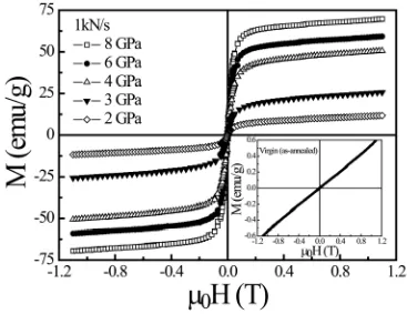
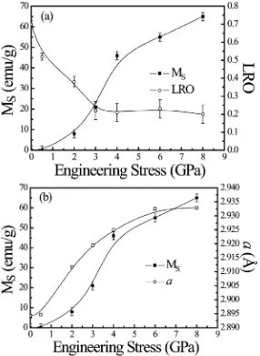
(29) Introduction. From a theoretical basis, the ferromagnetism of diluted and disordered transition metal alloys, such as Fe60Al40, has been partially explained by the so-called local environment model [63-65], which takes into account that the magnetic moment of a given atom (i.e., Fe in this case) depends on the number of nearest-neighbor atoms of the same species. Using this simple model, the effect of Al substitution and disorder in Fe60Al40 can be qualitatively explained. However, since variations in the distance between transition metal atoms, such as Fe, have profound effects on the magnetism, it has been shown that the origin of the magnetic interactions in disordered Fe60Al40 alloys may not arise solely from nearestneighbors magnetism (i.e., local environment model), but also from changes in the band structure of the material induced by changes in the lattice cell parameter (Δa) [59-61, 66-69]. Therefore, a two-fold origin of ferromagnetism is distinguished.. 1.3.2.. Ferromagnetism. induced. by. structural. phase. transformations in austenitic stainless steels Austenitic stainless steels (ASSs) are Fe-based alloys (see appendix for further information) which consist of a face-centered cubic (FCC) crystal lattice, designated as austenite (γ) phase. From a magnetic point of view, ASSs show paramagnetic behavior at room temperature, while they become antiferromagnetic below their Néel temperature, which is around 40 K [70]. However, due to strain-induced deformation, a phase transformation from the FCC austenite to a body-centered cubic (BCC) crystal structure, known as martensite (α′), can occur in these alloys. Since martensite is ferromagnetic [71-73], this stress-induced phase transformation also results in a magnetic transition at room temperature from paramagnetic γ to ferromagnetic α′ (γ → α′). Although the extent of the α′ transformation depends mainly on the chemical composition of the steel and the temperature at which the plastic deformation takes place, it should be noted that other important factors affecting this strain-induced phase transformation are the strain rate, grain size and deformation mode (i.e., stress state). In fact, the extent of this 19.
(30) Introduction. transformation (i.e., γ → α′) in different grades of austenitic stainless steels can be roughly shown in decreasing order as 304L >> 316 > 316L (see appendix for compositional details) when deformed to the same amount at a given temperature [74]. Furthermore, nitriding of ASSs at moderate temperatures (around 400 ºC) leads to the formation of the supersaturated nitrogen solid solution, often called in the literature “expanded austenite” or γN phase [75,76], which is responsible for both microhardness and wear resistance enhancement without loss of corrosion resistance. Remarkably, this phase shows ferromagnetic behavior, whose origin is linked to the expansion of the austenite (γ) lattice due to the incorporation of nitrogen atoms into interstitial positions [77]. Since the threshold for ferromagnetism is connected with nitrogen concentrations of ≈ 10-15 at. % [75,77], for thick specimens not the whole nitrided layer is ferromagnetic, thus rendering two magnetically dissimilar parts (one ferromagnetic and the other paramagnetic) depending on the nitrogen concentration along the depth of the nitrided surface layer.. 20.
(31) Introduction. References [1] J. I. Martín, J. Nogués, K. Liu, J. L. Vicent and I. K. Schuller J. Magn. Magn. Mater. 256 449 (2003) [2] Thin Film Processes, edited by J. L. Vossen and W. Kern (Academic Press, New York, 1978) [3] C. A. Ross Annu. Rev. Mater. Res. 31 203 (2001) [4] T. Pokhil, D. Song and J. Nowak J. Appl. Phys. 87 6319 (2000) [5] J. I. Martín, Y. Jaccard, A. Hoffmann, J. Nogués, J. M. George, J. L. Vicent and I. K. Schuller J. Appl. Phys. 84 411 (1998) [6] T. Schrefl, J. Fidler, K. J. Kirk and J. N. Chapman J. Magn. Magn. Mater. 175 193 (1997) [7] Y. Otani, S. G. Kim, T. Kohda and K. Fukamichi IEEE Trans. Magn. 34 1090 (1998) [8] J. Raabe, R. Pulwey, R. Sattler, T. Schweinböck, J. Zweck and D. Weiss J. Appl. Phys. 88 4437 (2000) [9] P. Vavassori, V. Metlushko, M. Grimsditch, B. Ilic, P. Neuzil, R. Kumar, Phys. Rev. B 61 5895 (2000) [10] Y. Yokoyama, Y. Suzuki, S. Yuasa, K. Ando, K. Shigeto, T. Shinjo, P. Gogol, J. Millat, A. Thiaville, T. Ono and T. Kawagoe J. Appl. Phys. 87 5618 (2000) [11] K. J. Kirk, J. N. Chapman, S. McVitie, P. R. Aitchison and C. D. W. Wilkinson J. Appl. Phys. 87 5105 (2000) [12] M. Schneider, H. Hoffmann and J. Zweck Appl. Phys. Lett. 77 2909 (2000) [13] T. Ono, H. Miyajima, K. Shigeto and T. Shinjo J. Magn. Magn. Mater. 198&199 225 (1999) [14] D. J. Smith, R. E. Dunin-Borkowski, M. R. McCartney, B. Kardynal and M. R. Scheinfein J. Appl. Phys. 87 7400 (2000) [15] S. Y. Chou, M. S. Wei, P. R. Krauss and P. B. Fischer J. Appl. Phys. 76 6673 (1994) [16] R. M. H. New, R. F. W. Pease and R. L. White J. Vac. Sci. Technol. B 12 3196 (1994). 21.
(32) Introduction. [17] C. C. Yao, D. G. Hasko, Y. B. Xu, W. Y. Lee and J. A. C. Bland J. Appl. Phys. 85 1689 (1999) [18] C. Shearwood, S. J. Blundell, M. J. Baird, J. A. C. Bland, M. Gester, H. Ahmed and H. P. Hughes J. Appl. Phys. 75 5249 (1994) [19] H. Demand, M. Hehn, K. Ounadjela, R. L. Stamps, E. Cambril, A. Cornette and F. Rousseaux J. Appl. Phys. 87 5111 (2000) [20] T. A. Savas, M. Farhoud, H. I. Smith, M. Hwang and C. A. Ross J. Appl. Phys. 85 6160 (1999) [21] C. Miramond, C. Fermon, F. Rousseaux, D. Decanini and F. Carcenac J. Magn. Magn. Mater. 165 500 (1997) [22] N. Bardou, B. Bartenlian, F. Rousseaux, D. Decanini, F. Carcenac, E. Cambril, M. F. Ravet, C. Chappert, P. Veillet, P. Beauvillain, R. Mégy, W. Geerts and J. Ferré J. Magn. Magn. Mater. 156 139 (1996) [23] W. Schwarzacher, O. I. Kasyutich, P. R. Evans, M. G. Darbyshire, G. Yi, V. M. Fedosyuk, F. Rousseaux, E.Cambril and D. Decanini J. Magn. Magn. Mater. 198-199 185 (1999) [24] W. Wu, B. Cui, X. Sun, W. Zhang, L. Zhuang, L. S. Kong and S. Y. Chou J. Vac. Sci. Technol. B 16 3825 (1998) [25] A. P. Li, F. Muller, A. Birner, K. Nielsch and U. Gosele J. Appl. Phys. 84 6023 (1998) [26] K. Liu, J. Nogués, C. Leighton, H. Masuda, K. Nishio, I. V. Roshchin and I. K. Schuller Appl. Phys. Lett. 81 4434 (2002) [27] H. R. Khan and K. Petrikowski J. Magn. Magn. Mater. 215-216 526 (2000) [28] P. R. Evans, G. Yi and W. Schwarzacher Appl. Phys. Lett. 76 481 (2000) [29] T. Thurn-Albercht, J. Schotter, G. A. Kästle, N. Emley, T. Shibauchi, L. KrusinElbaum, K. Guarini, C. T. Black, M. T. Tuominen and T. P. Russell Science 290 2126 (2000) [30] D. Streblechenko and M. R. Scheinfein J. Vac. Sci. Technol. A 16 1374 (1998) [31] D. Welipitiya, C. N. Borca, P. A. Dowben, I. Gobulukoglu, H. Jiang, B. W. Robertson and J. Zhang Mat. Res. Soc. Symp. Proc. 475 257 (1997) [32] K. Bessho, Y. Iwasaki and S. Hashimoto J. Appl. Phys. 79 5057 (1996). 22.
(33) Introduction. [33] S. Wirth, J. J. Heremans, S. von Molnár, M. Field, K. L. Campman, A. C. Gossard and D. D. Awschalom IEEE Trans. Magn. 34 1105 (1998) [34] W. Schindler, D. Hofmann and J. Kirshner J. Appl. Phys. 87 7007 (2000) [35] K. Koike, H. Matsuyama, Y. Hirayama, K. Tanahashi, T. Kanemura, O. Kitakami and Y. Shimada Appl. Phys. Lett. 78 784 (2001) [36] J. Fassbender and J. McCord J. Magn. Magn. Mater. 320 579 (2008) [37] C. Chappert, H. Bernas, J. Ferre, V. Kottler, J. P. Jamet, Y. Chen, E. Cambril, T. Devolder, F. Rousseaux, V. Mathet and H. Launois Science 280 1919 (1998) [38] S. W. Shin, S. G. Lee, J. Lee, C. N. Whang, J. H. Lee, I. H. Choi, T. G. Kim and J. H. Song Nanotechnology 16 1392 (2005) [39] B. D. Terris, L. Folks, D. Weller, J. E. E. Baglin, A. J. Kellock, H. Rothuizen and P. Vettiger Appl. Phys. Lett. 75 403 (1999) [40] S. Konings, J. Miguel, J. Goedkoop, J. Camarero and J. Vogel J. Appl. Phys. 100 033904 (2006) [41] M. Abes, J. Venuat, A. Carvalho, J. Arabski, D. Muller, G. Schmerber, E. Beaurepaire, P. Panissod, A. Dinia and V. Pierron-Bohnes J. Magn. Magn. Mater. 286 297 (2005) [42] G. J. Kusinski, K. M. Krishnan, G. Denbeaux and G. Thomas Scr. Mater. 48 949 (2003) [43] B. D. Terris, D. Weller, L. Folks, J. E. E. Baglin, A. J. Kellock, H. Rothuizen and P. Vettiger J. Appl. Phys. 87 7004 (2000) [44] T. Hasegawa, G. Q. Li, W. Pei, H. Saito, S. Ishio, K. Taguchi, K. Yamakawa, N. Honda, K. Ouchi, T. Aoyama and I. Sato J. Appl. Phys. 99 053505 (2006) [45] D. Ozkaya, R. M. Langford, W. L. Chan and A. K. Petford-Long J. Appl. Phys. 91 9937 (2002) [46] M. Albrecht, C. T. Rettner, M. E. Best and B. D. Terris Appl. Phys. Lett. 83 4363 (2003) [47] A. Dietzel, R. Berger, H. Loeschner, E. Platzgummer, G. Stengl, W. H. Bruenger and F. Letzkus Adv. Mater. 15 1152 (2003) [48] S. I. Woods, S. Ingvarsson, J. R. Kirtley, H. F. Hamann and R. H. Koch Appl. Phys. Lett. 81 1267 (2002). 23.
(34) Introduction. [49] J. McCord, T. Gemming, L. Schultz, J. Fassbender, M. O. Liedke, M. Frommberger and E. Quandt Appl. Phys. Lett. 86 162502 (2005) [50] J. Fassbender, J. von Borany, A. Muecklich, K. Potzger, W. Möller, J. McCord, L. Schultz and R. Mattheis Phys. Rev. B 73 184410 (2006) [51] A. Mougin, S. Poppe, J. Fassbender, B. Hillebrands, G. Faini, U. Ebels, M. Jung, D. Engel, A. Ehresmann and H. Schmoranzer J. Appl. Phys. 89 6606 (2001) [52] J. Fassbender, D. Ravelosona and Y. Samson J. Phys. D: Appl. Phys. 37 R179 (2004) [53] K. Theis-Bröhl, M. Wolff, A. Westphalen, H. Zabel, J. McCord, V. Hoeink, J. Schmalhorst, G. Reiss, T. Weis, D. Engel, A. Ehresmann, U. Rucker and B. P. Toperverg Phys. Rev. B 73 174408 (2006) [54] T. Aign, P. Meyer, S. Lemerle, J. P. Jamet, J. Ferre, V. Mathet, C. Chappert, J. Gierak, C. Vieu, F. Rousseaux, H. Launois and H. Bernas Phys. Rev. Lett. 81 5656 (1998) [55] D. McGrouther and J. N. Chapman Appl. Phys. Lett. 87 022507 (2005) [56] M. T. Georgieva, P. J. Grundy and N. D. Telling Appl. Phys. Lett. 90 042509 (2007) [57] W. M. Kaminsky, G. A. C. Jones, N. K. Patel, W. E. Booij, M. G. Blamire, S. M. Gardiner, Y. B. Xu and J. A. C. Bland Appl. Phys. Lett. 78 1589 (2001) [58] G. K. Wertheim, V. Jaccarino, J. H. Wernick and D. N. E. Buchanan Phys. Rev. Lett. 12 24 (1964) [59] E. P. Yelsukov, E.V. Voronina and V. A. Barinov J. Magn. Magn. Mater. 115 271 (1992) [60] X. Amils, J. Nogués, S. Suriñach, M. D. Baró and J. S. Muñoz IEEE Trans. Magn. 34 1129 (1998) [61] A. Hernando, X. Amils, J. Nogués, S. Suriñach, M. D. Baró and M. R. Ibarra Phys. Rev. B Rapid Comm. 58 R11864 (1998) [62] A. Taylor and R. M. Jones J. Phys. Chem. Solids 6 16 (1958) [63] P. A. Beck Metall. Trans. 2 2015 (1971) [64] G. K. Wertheim, V. Jaccarino, J. H. Wernick and D. N. E.Buchanan Phys. Rev. Lett. 12 24 (1964) [65] S. Takahashi J. Magn. Magn. Mater. 54-57 1065 (1986). 24.
(35) Introduction. [66] M. Fujii, K. Saito, K. Wakayama, M. Kawasaki, T. Yoshioka, T. Isshiki, N. Nishio and M. Shiojiri Philos. Mag. A 79 2013 (1999) [67] A. V. Smirnov, W. A. Shelton and D. D. Johnson Phys. Rev. B 71 064408 (2005) [68] E. Apiñaniz, F. Plazaola and J. S. Garitaonandia Eur. Phys. J. B 31 167 (2003) [69] J. Nogués, E. Apiñaniz, J. Sort, M. Amboage, M. d'Astuto, O. Mathon, R. Puzniak, I. Fita, J. S. Garitaonandia, S. Suriñach, J. S. Muñoz, M. D. Baró, F. Plazaola and F. Baudelet Phys. Rev. B 74 024407 (2006) [70] J. Ding, H. Huang, P. G. McCormick and R. Street J. Magn. Magn. Mater. 139 109 (1995) [71] S. S. Hecker, M. G. Stout, K. P. Staudhammer and J. L. Smith Metall. Trans. A 13 619 (1982) [72] E. Nagy, V. Mertinger, F. Tranta and J. Sólyom, Mater. Sci. Eng. A 378 308 (2004) [73] H. Ishigaki, Y. Konishi, K. Kondo and K. Koterazawa J. Magn. Magn. Mater. 193 466 (1999) [74] J. Manjanna, S. Kobayashi, Y. Kamada, S. Takahashi and H. Kikuchi J. Mater. Sci. doi:10.1007/s10853-008-2494-4 [75] M.P. Fewell, D. R. G. Mitchell, J. M. Priest, K. T. Short and G. A. Collins Surf. Coat. Technol. 131 300 (2000) [76] G. Abrasonis, J. P. Riviere, C. Templier, A. Declemy, L. Pranevicius and X. Milhet J. Appl. Phys. 97 083531 (2005) [77] O. Öztürk and D. L. Williamson J. Appl. Phys. 77 3839 (1995). 25.
(36) Introduction. 26.
(37) Experimental methods. 2. Experimental methods This chapter describes the experimental procedures that have been used to induce ferromagnetism in Fe60Al40 (at. %) alloys and austenitic stainless steels (ASSs) by means of either plastic deformation (mechanical milling and compression testing) or ion irradiation (broad beam ion irradiation and focused ion beam). Subsequently, the techniques for structural, morphological, mechanical, and magnetic characterization are surveyed.. In each section, the employed setups for either material processing or characterization are specified. Although the specific experimental details will be concisely presented at the beginning of each section of the Results and discussion chapter, a brief description of the main working conditions is given here.. 27.
(38) Experimental methods. 2.1. Processing methods. 2.1.1. Mechanical milling. 2.1.1.1. Fundamentals Mechanical milling is a solid state powder treatment technique involving repeated welding, fracturing, and re-welding of powder particles in a high-energy ball mill [1]. In most cases, this processing route has been successfully utilized to produce many types of solid solutions, materials in non-equilibrium states [2,3], disordered and amorphous alloys, and to induce mechanochemical reactions [4]. Furthermore, mechanical milling has established itself as a very effective process for producing nanocrystalline powders and synthesizing metal-ceramic composite powders [1,5]. Even though a large variety of milling devices, such as shaker (e.g., Spex mills), attritor or magnetic mills, are currently often used, this section is focused on planetary-like ball mills since a planetary ball mill (see Figure 2.1) has been used to treat the AISI 316L ASS powders. Moreover, this type of milling apparatus is characterized by their capability to carry out very energetic processes.. Figure 2.1. Photograph of the employed planetary ball mill (Fritsch Pulverisette 7). Note that the milling chamber contains a disk with two symmetrically located grinding bowls (vials).. 28.
(39) Experimental methods. Concerning the operational principle, a powder load is introduced in one or more vials (grinding bowls), which are arranged, together with some balls, on a rotating support disk. After appropriate sealing, the vials rotate around their own axis and, simultaneously, around a central axis, similar to a planetary system [1,4,6]. Since the vials and the supporting disk rotate in opposite directions, the centrifugal forces of the two movements act alternately in the same and opposite directions. This causes the grinding balls to run down the inner wall of the vial –the friction effect–, followed by the material being ground and grinding balls lifting off and traveling through the inner chamber of the vial and colliding against the opposing internal wall –the impact effect– (see Figure 2.2) [1].. Figure 2.2. Schematic diagram of balls and powders movements in a planetary ball mill [1]. (i) and (ii) stand for the grinding and impact effects, respectively. ωd and ωv are the angular frequencies of the supporting disk and the vials, respectively.. 2.1.1.2. Milling parameters The main experimental parameters that must be taken into account in order to control the final products of a milling process are: - Intensity (transferred power) - Atmosphere - Media. 29.
(40) Experimental methods. - Temperature. 2.1.1.2.1. Intensity (transferred power) Several theoretical models have been developed in order to evaluate the milling intensity I (i.e., the power transferred to the load) [7]. Even though these models can differ noticeably due to their particular simplifications and approximations, I is often estimated using an expression which contains the following parameters: I = ν·ΔE·n·f (Eq. 2.1),. whit ΔE being the dissipated energy in a system containing n balls, ν a variable less than unity, whose value depends on the volume occupied by the balls inside the vials, and f the frequency at which the balls are thrown to the opposite walls of the vials, which, in the case of a planetary mill, is a function of the angular frequencies of the supporting disk and the vials, ωd and ωv, respectively. If one considers simplified models in which the energy can only be dissipated during the impacts between the balls and the walls of the vials, ΔE only depends on some intrinsic parameters of the planetary mill, such as the distance between the center of the disk and walls of the vials, and the distance between the center of the disk and the center of the vials [8,9]. Moreover, there are other relevant parameters, such as the ball-topowder mass ratio or the milling time, that play an important role in the amount of energy transferred and, therefore, in controlling the final properties of the milled material [1].. 2.1.1.2.2. Milling atmosphere The control of the milling atmosphere is of great importance, since lack of it can lead to some undesired mechanochemical reactions or contamination in the obtained materials. For instance, if the milling is performed in air, a significant contamination from oxygen or nitrogen can be obtained [10]. Usually these effects are not desirable and, therefore, 30.
(41) Experimental methods. the milling process is commonly carried out under vacuum or in an inert gas, such as argon or helium.. 2.1.1.2.3. Milling media The contamination arising from the milling media (vials and balls) can also be significant during the material processing. The amount of this type of contamination depends mainly on how energetic is the milling process and also on the mechanical properties (e.g., hardness) of the powders that are being ground with respect to those corresponding to the milling media [11]. Nevertheless, this problem can be almost ignored when the milling media are built up from the same material as the powders [12].. 2.1.1.2.4. Milling temperature In milling, the exchange of energy during both the friction and impact effects usually brings about a heating of the powders, which can, undoubtedly, affect their microstructure [4,12]. Essentially, this temperature increase is observed locally at the surface of the particles and is usually known as microscopic temperature rise. Moreover, an overall heating in the milling media, due to the motor, the friction among the components of the mill or the impacts between the vial and the balls, can be also detected (i.e., macroscopic temperature rise). The macroscopic temperature increase that can be observed in the different types of milling apparatus is generally not very high and has been measured by several authors. For example, the average temperature during milling has been reported to be of up to 50 ºC for Spex mills, 120 ºC for vibratory mills and 172 ºC for attritor mills [4]. Conversely, the microscopic temperature of the powders, just after each impact, can be really high. Actually, it is unfeasible to directly measure this temperature and, for that reason, its values can only be inferred by using some theoretical models or by analyzing the microstructural changes which take place in the powders upon milling. For instance,. 31.
(42) Experimental methods. Schwarz and Koch estimated a temperature increase (with respect to room temperature) of 350 ºC for Spex-type mills [13]. Magini et al. calculated that the temperature rise could reach up to 400 ºC for planetary mills [14]. Although a wide range of microscopic temperature increases have been reported in the literature, the macroscopic temperature (and to a certain extent the microscopic one) can be occasionally controlled by means of refrigerating circuits [4].. 2.1.1.3. Temporal evolution of the microstructure Typically, in materials subjected to mechanical work in high energetic mills, the final distribution of particle sizes and shapes, after long-term milling, becomes rather stable due to the continuous processes of fracture and welding. The particle size distribution and particle morphology depend on the kind of material being processed as well as the milling intensity, the ball-to-powder mass ratio, temperature, etc. However, the homogenization process varies depending on the ductility or brittleness of the milled powders. Thus, very different microstructures are frequently obtained when the precursor powders are ductile, brittle or two-component brittle-ductile. Most of alloys synthesized by ball milling are of ductile character, such as AISI 316L ASSs. In this case, the particles increase in size up to a maximum value and, then, tend to progressively reduce until an equilibrium dimension is reached. This behavior can be interpreted as the interplay between fracture and welding mechanisms. Hence, during the first milling stages, owing to the ductility of the powders, soldering predominates over fracturing. However, for long-term milling, both processes tend to reach some equilibrium, leading to a stationary particle size distribution. Furthermore, during milling, the particles first become elongated and later they develop in platelet or laminar shapes. As the milling time increases, the interlaminar distances decrease, the microstructure becomes more and more refined and, finally, homogenization is attained [1,15,16].. 32.
(43) Experimental methods. 2.1.1.4. Working conditions The AISI 316L ASS powders have been ball-milled with a Fritsch Pulverisette 7 milling apparatus, located at the Universitat Autònoma de Barcelona, using hardened stainless steel vials (20 ml in volume) and balls (3 balls of 1 cm diameter). Note that although some iron contamination arising from the vials and balls can be found, this is expected to be lower than 1 mass % [17]. It should be mentioned that even though hardened stainless steel leads to a more energetic milling than other media, such as agate or zirconia, due to its larger density, a rather small ball-to powder mass ratio has been chosen in the Thesis in order to allow a better control of the microstructural changes with milling time.. 2.1.2. Uniaxial compression testing The response of a material to the application of a mechanical load depends on its mechanical properties. Materials can be subjected to different loading designs, such as compression, torsion or tensile modes, and the resulting properties (e.g., mechanical or magnetic) can depend on these loading conditions. Typically, in compression testing, a specimen is subjected to a continuously increasing uniaxial compressive load until it fractures. Load (P) and displacement (Δl) are carefully recorded at a certain deformation velocity, previously programmed. The outcome of a compression test is a load-displacement curve, which is commonly converted into a (compressive) stress (σ)-strain (ε) curve as follows:. σ engineering =. P·g F = (Eq. 2.2) A0 A0 and. 33.
(44) Experimental methods. ε engineering =. Δl l0 − l = (Eq. 2.3), l0 l0. with A0 the (initial) cross section area on which the load is applied, l0 the initial length of the tested specimen and g the acceleration of gravity. Note that in this case, both the compressive stress (σ) and the deformation (ε) are expressed in such a way to represent them on the positive axes. Since these values of tension and deformation are referred to the initial morphology of the samples, this plot is denoted as engineering stress-strain curve [18].. 2.1.2.1. Working conditions Compression tests of either bulk Fe60Al40 (at. %) alloys or AISI 316L ASS samples have been performed with the aim to obtain different degrees of mechanical work. Specifically, a load control mode, with a fixed loading rate, is used in order to perform compression functions consisting of a loading segment until a certain target engineering stress, previously programmed, is reached, followed by a load holding segment and, then, by an unloading step executed at the same loading rate in absolute value.. The compression processes have been performed uniaxially, at room temperature, using a MTS 858 Table Top System Universal/Tensile apparatus, located at the Universitat Autònoma de Barcelona.. 2.2. Irradiation methods. This part introduces some general issues of ion-solid interactions and describes the ion irradiation techniques (i.e., broad beam ion irradiation and focused ion beam) utilized to modify the surface of target materials (i.e., Fe60Al40 and ASSs). In addition, the lithography process to produce shadow masks on Fe60Al40 sheets by means of an electron beam writer is also presented.. 34.
(45) Experimental methods. Since all the irradiation processes have been performed perpendicularly to the target surface, this is the irradiation configuration that has been considered to describe the aspects related to ion-solid interactions.. 2.2.1. Broad beam ion irradiation. Since it is not the goal of this work to focus on ion-solid interactions, only a brief introduction of the main phenomena which take place in a target material upon irradiation is surveyed. Furthermore, the experimental setups for the diverse broad beam ion irradiations are described.. 2.2.1.1. Essentials on ion-solid interactions. The interaction of an energetic ion with a target involves several processes. As an ion penetrates a solid, it slows down by transferring energy to both the atoms and the electrons of the material. Namely, ion kinetic energy and momentum are transferred to the target through both inelastic and elastic interactions. In inelastic interactions, ion energy is lost to the electrons in the sample and results in ionization and the emission of electrons and electromagnetic radiation from the solid. Conversely, ion energy is transferred as translational energy to target atoms in elastic interactions and can result in damage (displacement of sample atoms from their initial sites) and sputtering from the sample surface.. In these interactions, the incident ion loses energy, E, at a rate of. dE (also known as ds. stopping power), which is the energy loss by the ion in the target per unit traversed distance, s. Typically, its magnitude ranges from of a few to 100 electron-volts per nanometer, depending on the energy and mass of the ion as well as on the substrate. 35.
Figure

![Figure 1.2. Aluminum content dependence of the saturation magnetization, Msystem. Adapted from reference [62]](https://thumb-us.123doks.com/thumbv2/123dok_es/5318328.98635/28.595.145.454.461.683/figure-aluminum-dependence-saturation-magnetization-msystem-adapted-reference.webp)

![Figure 2.5. Schematic picture of the main components of a 1090 Danfysik ion implanter [27]](https://thumb-us.123doks.com/thumbv2/123dok_es/5318328.98635/56.595.129.467.328.549/figure-schematic-picture-main-components-danfysik-ion-implanter.webp)
+7
![Figure 2.7. Schematic representation of the implantation device [28].](https://thumb-us.123doks.com/thumbv2/123dok_es/5318328.98635/59.595.151.444.166.409/figure-schematic-representation-implantation-device.webp)
![Figure 2.8. Schematic image of a dual-beam FIB-SEM instrument. The expanded view illustrates electrons and ion beam sample interaction [31]](https://thumb-us.123doks.com/thumbv2/123dok_es/5318328.98635/60.595.139.460.463.695/figure-schematic-instrument-expanded-illustrates-electrons-sample-interaction.webp)

Documento similar
As shown in Figure 4 in the case of the 385 nm wavelength, the results provided by the LED reach deviations in the range of 14–20% with respect to the values obtained by means of
In addition, precise distance determinations to Local Group galaxies enable the calibration of cosmological distance determination methods, such as supernovae,
In the preparation of this report, the Venice Commission has relied on the comments of its rapporteurs; its recently adopted Report on Respect for Democracy, Human Rights and the Rule
Astrometric and photometric star cata- logues derived from the ESA HIPPARCOS Space Astrometry Mission.
The photometry of the 236 238 objects detected in the reference images was grouped into the reference catalog (Table 3) 5 , which contains the object identifier, the right
Similarly to the case of laminated structures, which are usually in nonresonant acoustic structures, second order Taylor expansion of the transfer matrix elements is sufficient
In the “big picture” perspective of the recent years that we have described in Brazil, Spain, Portugal and Puerto Rico there are some similarities and important differences,
Keywords: iPSCs; induced pluripotent stem cells; clinics; clinical trial; drug screening; personalized medicine; regenerative medicine.. The Evolution of
