Mineral Compositions Visualization
Implementing the Spinel Prism
Mar´ıa Luj´an Ganuza1,3, Silvia Castro1, Sergio Martig1, Gabriela Ferracutti2
and Ernesto Bjerg2
1Universidad Nacional del Sur
Departamento de Ciencias e Ingenier´ıa de la Computaci´on Laboratorio de Investigaci´on y Desarrollo
en Visualizaci´on y Computaci´on Gr´afica.
Avenida Alem 1253, Bah´ıa Blanca, Buenos Aires, Argentina. CP 8000 2
Ingeosur
Departamento de Geolog´ıa
San Juan 670, Bah´ıa Blanca, Buenos Aires, Argentina. CP 8000 3
Comisi´on de Investigaciones Cient´ıficas de la Provincia de Buenos Aires (CIC) Calle 526 entre 10 y 11, La Plata, Buenos Aires, Argentina. CP 1900
{mlg,smc,srm}@cs.uns.edu.ar,{gferrac}@uns.edu.ar,{ebjerg}@ ingeosur-conicet.gob
http://vyglab.cs.uns.edu.ar
Abstract. An important problem in Mineralogy, is to accomplish an adequate representation of a great amount of data coming from different geological environments, in order to characterize a particular geologic region in terms of its tectonic setting. With such Databases of min-eral compositions it is possible to define the compositional fields that constitute a reference pattern to classify an unclassified data sample. Mineralogic patterns are represented in ad-hoc tree dimensional spaces that could be prismatic or tetragonal. In this context we developed the Spinel Prism Viewer, a Geological Visualization Application consisting on a 3D Viewer which allows the user to watch, explore and interact with the Spinel Prism and different Datasets at the same time. The Viewer provides projection tools in 2D and 3D, helping the users to understand the tectonic identity of a particular mineral composition represented on the view.
Key words: Scientific Visualization, Interactions, Spinels, Geological Sciences.
1
Introduction
Visualization is essential in interpreting data for many scientific problems. It transforms numerical data into a visual representation which is much easier to understand for humans. Other tools such as statistical analysis may present only a global or localized partial view on the data [2].
The exploration of Datasets originated from Natural Sciences, and Geolog-ical Sciences in particular, involves the application of interactive visualization tools and techniques. In this paper we study visualization if an special group of minerals called Spinels. Minerals that integrate the group of Spinels represent a great compositional variety linked to their genesis. This implies the fact that some minerals of the group, chromite minerals in particular, have been used as “Petrogenetic indicators”[6, 3, 4], since they provide vital information regarding the tectonic setting of the rocks present in an area, in the context of global tectonics.
To achieve a significant evaluation of data samples in this context, it becomes necessary to have a big number of data coming from different geological environ-ments. With such databases of mineral compositions it is possible to define the compositional fields that constitute a reference pattern to classify an unclassified data sample.
Without a doubt, building a referential field with such a big amount of data, (more than 20.000), and at the same time include in a graph the data of a new population are tasks that require a big amount of time inversion if they are not implemented on an automated way. All this has set the necessity to visualize data on their natural domain, making easier the comparisons and integration of multiple Datasets.
Taking all of this into account we developed a Geological Visualization Ap-plication called Spinel Prism Viewer. The apAp-plication consists on a 3D Viewer which allows the user to watch, explore and interact with the Spinel Prism and different Datasets at the same time. The Spinel Prism Viewer provides the ca-pability of project Datasets over the different faces of the prism in 2D and 3D, helping the user to understand easily the mineralogic composition represented on the view.
2
Application Field
An important problem in Mineralogy is to achieve an adequate representation of mineral compositions, in a way that groups of samples can be intuitively matched against a given pattern. Mineralogic patterns are represented in ad-hoc tree dimensional spaces that could be prismatic or tetragonal. In this paper we are studying the prismatic representation, where each apices of the prism are determined by the composition of the Data Sample Group (Figure 1(a)). These Prism is called Spinel Prism.
char-acterizes that particular mineral, and can be represented as a solid within the composition space.
(a) Prismatic composition space of stan-dard mineral.
[image:3.595.139.476.162.299.2](b) A prismatic composition space of stan-dard mineral oxides, and the volumetric pattern that identify minerals from a par-ticular rock, (basalts in this case) .
Fig. 1.Prismatic Space [6]
Data from a given set of unclassified samples may be represented in this space with an adequate icon, and the classification problem is now to visually determine if these icons lay within the pattern or not. However, the set of sam-ples is normally a huge, of variable size and subject to change. Then, a better representation aid should be to find and adequately represent a set of samples as a whole.
2.1 Sample Representation within the Spinel Prism
In this section we want to introduce the process of positioning a sample within the Prism(Figure 3). In the prismatic representation, each apices of the prism is determined by the composition of the minerals of the Spinel Group. In this case to represent the samples on the prism the Magnesium (M g), Iron (F e), Chrome (Cr) and Aluminium (Al) proportions are taken into account. As illustrated in Figure 3, the ternary on the left of the prism hasM g as the common element, and the ternary to the right has F e2+ as the common element [3].
To understand how a data sample is positioned within the Spinel Prism and only as an example, projections of a particular data sample over the faces of the Prism are shown. In this case, we consider a data sample composed by the following values for each component:
Fig. 2.A data sample within the Spinel Prism.
– Aluminium(Al) = 21% – Chrome(Cr) = 32%
An useful projection of this particular data is shown in Figure 3(a). The projec-tion on this face is given by the following expression:
2F e3+
2F e3++Al+Cr (1)
Equation (1) defines where the sample is going to be positioned according to the edge determined by theF eAl2O4 andF e3O4apices of the Spinel Prism.
F e2+
F e2++M g (2)
Equation (2) defines where the sample is going to be positioned according to the edge determined by theM gAl2O4 andF eAl2O4apices of the Spinel Prism. Figure 3(b) shows another useful projection, the projection on the spinel prism base. In this case the expression (2) detailed above is applied for the edge deter-mined by the M gAl2O4 andF eAl2O4, shared by both faces of the Prism, and expression (3) is used to positioning the sample according to the edge determined by theM gAl2O4 andM gCr2O4 apices.
Cr
Cr+Al (3)
Finally, equations 1, 2 and 3 gives the coordinates of the data sample within the Spinel Prism.
3
Related Work
(a) (b) (c)
Fig. 3.Plotting procedure for compositions in the multicomponent Spinel Prism. Co-ordinates of a the data sample detailed above. The position of the sample is determined by equation (1) 2F e3+
/2F e3+
+Al+Cr= 0.4 , equation (2)F e2+ /F e2+
+M g= 0.6 and equation (3)Cr/Cr+Al= 0.6 [3].
different projections over the faces of the Prism as it was explained on section 2.1. To achieve these projections several applications has been developed, most of them implement triangular diagramming in two dimensions. Clearly a tree dimensional interactive visualization might be very useful to Geological Scien-tists who need to study Spinels Datasets, because although 2d projection tools exist, they don’t provide any interaction over the view or the capabilities of inte-grate projections with the spinel prism in order to get a better idea of the visual context. Until the moment no tree dimensional application has been developed yet.
4
Spinel Prism Visualization Application
The Spinel Prism Viewer presented provides an interactive visual representa-tion of these group of minerals that constitute Tectonic Tracers using the Spinel Prism. The application was customized to handle specific types of data, allow-ing the analysis of special relationship between data. It presents Mineralogic Datasets within the Spinel Prism following equations 1, 2 and 3 (section 2.1), providing interactions to the user to allow navigation over the prismatic space and exploration of data.
In Figure 4 a screen capture of the Spinel Prism is shown, in this case a data set is plotted inside the prism.
Fig. 4.Spinel Prism Viewer.
The Spinel Prism Viewer composed by tree main components: the Mathe-matics Framework, The Visual Representation and the Interactions sets.
5
Mathematical Framework
The mathematical framework is a major component of the Spinel Prism Appli-cation. The goal of the Math Framework is to provide a specific solver for the mathematical problems in the application domain. These problems include the calculation of coordinates and projection of each data sample within the Spinel Prism; which constitute very important for the correct result of the visualization. The fact that projections are shown on 3D and 2D adds an additional diffi-culty to calculations, so it seems attractive to separate the Mathematics Frame-work as a independent module.
6
The Visual Representation
The visual representation involves the definition of the spatial substrate, the aso-ciation of visual elements to represent data elements and the graphical attributes of those elements.
An important task of our application is to achieve an adequate representation of mineral compositions, in a way that groups of samples can be intuitively matched against a given pattern. Spinel Prism Viewer represents the mineralogic composition of each data sample with an Sphere within the Prism. The position of the Sphere is given by equations 1, 2 and 3 (section 2.1).
these patterns the Spinel Prism Viewer use transparency over the Spheres; al-lowing a set of data samples situated on neighborhood positions to constitute a volume within the Prism. Data samples from different patterns are represented with different colors, allowing the visualization of two or more referential pat-terns within the same prismatic space (See Figure 5(a)).
To see if a data sample belongs to a certain pattern, the Application rep-resents the data set with a different color from the color used for the patterns (See Figure 5(b)), and with the help of transparency the user can navigate over the 3D space to realize if the data sample lay inside a pattern or outside. As an example of these feature Figures 6(a) and 6(b) illustrate the application of the zoom interaction over the scene, allowing the user to get closer to the data sample to verify if it belongs to a pattern or not. In this case, by getting closer to the sample, we realize that in fact it belongs to one of the two given patterns.
[image:7.595.166.460.304.435.2](a) (b)
Fig. 5.Spinel Prism Viewer allows the user to load more than one pattern. Figure (a) illustrates this capability, showing two different patterns inside the prism . Notice that the patterns can be differentiated by the color of the Spheres. One pattern has been drawn in green and the other in purple. In Figure (b) a new data sample has been added in red color.
7
Interactions
(a) (b)
Fig. 6.Zooming over the prismatic space. Figure (a): Zoom interaction applied to the scene, attempting to get closer to the data sample. On Figure (b), with more zoom, is clear that the data sample lays inside the purple pattern.
Show/Hide Projections 2D The projection of each data sample within the Spinel Prism is a very important task. Our approach provides the user with two ways to see, explore and analyze these projection. The fist approach consists of 2D projection of the five faces of the Prism with the corresponding data sample projected over them. These 2D projections are shown on a different window, and can be closed and opened at any time within the application execution (See figure 7(b)).
Show/Hide Projection 3D The 3D projection is basically a 2D projection integrated in the 3D scene with the Spinel Prism. The 3D projection is shown in the same window as the Spinel Prism, drawing all the projected faces over a plane parallel to the Prism and situated behind it. This integration brings the user a better idea of the context of each projection, and allows interactions with the Spinel Prism and projections at the same time (See figure 7(c)).
Show/Hide Grid The Viewer allows the user to activate and hide referential Grids on the faces of the prism. These referential grids are used to give the user a notion of the mineralogic composition of a sample according to the projection of it over the faces of the prism. Referential grids are shown on Figures 3(b) and 3(a).
Change/Select Color of Spheres This interaction provides the user the ca-pability of changing the color of a whole pattern, a set of data samples, or a unique sample.
the scene, the user can get closer to the new data sample and discover if its placed inside pattern or not, as has been seen on figure 6.
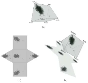
(a)
[image:9.595.158.456.162.446.2](b) (c)
Fig. 7.Spinel Prism Projection Example. Figure (a) shows the data set to be projected, figure (b), shows a screen capture of the 2D projection of the data set; and figure (c) shows the 3D projection of the data set integrated with the Spinel Prism.
8
Conclusions and Future Work
extend the interactions set, including tools which allow to get more information of each data set on demand of the user. For example, we aim to include an in-teraction that shows the mineralogical composition of a sample when the user select it. Finally, some user evaluation is expected to be done, in order to obtain a quantitative measure of the effectiveness of our Application.
Acknowledgments. This work was supported in part by the PGI 24/N020 and 24/ZN19, Secretar´ıa General de Ciencia y Tecnolog´ıa, Universidad Nacional del Sur, Bah´ıa Blanca, Argentina.
References
1. McCormick, B. H., 1988. “Visualization in scientific compu-ting”. SIGBIO Newsl.ACM, Vol.10, pp.15–21. ISSN:0163-5697. http://doi.acm.org/10.1145/43965.43966.
2. Cover Design Michal Koutek and Michal Koutek, 2003. “Scientific Visualization in Virtual Reality: Interaction Techniques and Application Development”.
3. Lindsley, D., 2001. “Oxide Minerals, Petrologic and Magnetic Significance, Reviews in Mineralogy”. Reviews in Mineralogy Mineralogical Society of America. ISBN 0-939950-30-8
4. Castro, S., Silvetti, A., Delrieux C. and Bjerg, E., 1999. “Visualizaci´on de Com-posiciones Minerales”. Workshop de Investigadores en Ciencias de la Computaci´on (WICC 99). San Juan, Argentina.
5. Castro S., Danzi M., Delrieux C., Larrea M. and Silvetti A., 1997. “Low-Cost Volume Visualization”. Proceedings International Conference on Imaging Science, Systems and Technology, CISST’97. Pp. 486-493. ISBN 0-9648666-9-2. Nevada, EEUU
6. Castro S., Danzi M., Delrieux C., Larrea M. and Silvetti A., 1997. “Low-Cost Volume Visualization”. Proceedings International Conference on Imaging Science, Systems and Technology, CISST’97. Pp. 486-493. ISBN 0-9648666-9-2. Nevada, EEUU
7. CSGL. C# Graphics Library, http://csgl.sourceforge.net.
8. OpenGL, The Industry’s fundation of High Performance Graphics, http://www.opengl.org.
![Fig. 1. Prismatic Space [6]](https://thumb-us.123doks.com/thumbv2/123dok_es/4608984.44333/3.595.139.476.162.299/fig-prismatic-space.webp)