INSTITUTO TECNOLÓGICO Y DE ESTUDIOS SUPERIORES DE
MONTERREY
PRESENTE.-Por m edio de la presente hago constar que soy autor y titular de la obra
denom inada"
, en los sucesivo LA OBRA, en virtud de lo cual autorizo a el Instituto
Tecnológico y de Estudios Superiores de Monterrey (EL INSTITUTO) para que
efectúe la divulgación, publicación, com unicación pública, distribución,
distribución pública y reproducción, así com o la digitalización de la m ism a, con
fines académ icos o propios al objeto de EL INSTITUTO, dentro del círculo de la
com unidad del Tecnológico de Monterrey.
El Instituto se com prom ete a respetar en todo m om ento m i autoría y a
otorgarm e el crédito correspondiente en todas las actividades m encionadas
anteriorm ente de la obra.
De la m ism a m anera, m anifiesto que el contenido académ ico, literario, la
edición y en general cualquier parte de LA OBRA son de m i entera
responsabilidad, por lo que deslindo a EL INSTITUTO por cualquier violación a
los derechos de autor y/ o propiedad intelectual y/ o cualquier responsabilidad
relacionada con la OBRA que com eta el suscrito frente a terceros.
Stereovision Feedback and Fuzzy Control for Autonomous
Robot Navigation-Edición Única
Title
Stereovision Feedback and Fuzzy Control for Autonomous
Robot Navigation-Edición Única
Authors
Aristeo Hernández Martínez
Affiliation
Tecnologíco de Monterrey, Campus Monterrey
Issue Date
2010-12-01
Item type
Tesis
Rights
Open Access
Downloaded
18-Jan-2017 19:31:51
I N S T I T U T O T E C N O L O G I C O Y D E E S T U D I O S
S U P E R I O R E S D E M O N T E R R E Y
C A M P U S M O N T E R R E Y
D I V I S I O N D E M E C A T R O N I C A Y T E C N O L O G I A S D E L A I N F O R M A C I O N
STEREOVISIÓN F E E D B A C K A N D F U Z Z Y C O N T R O L
F O R A U T O N O M O U S R O B O T N A V I G A T I O N
T H E S I S
P R E S E N T E D A S A P A R T I A L R E Q U I S I T E T O O B T A I N T H E D E G R E E :
M A S T E R O F S C I E N C E I N A U T O M A T I O N
B Y :
A R I S T E O H E R N Á N D E Z M A R T Í N E Z
I N S T I T U T O T E C N O L O G I C O Y D E E S T U D I O S
S U P E R I O R E S D E M O N T E R R E Y
C A M P U S M O N T E R R E Y
D I V I S I O N D E M E C A T R O N I C A Y T E C N O L O G I A S D E L A I N F O R M A C I O N
S T E R E O V I S I O N F E E D B A C K A N D F U Z Z Y C O N T R O L
F O R A U T O N O M O U S R O B O T N A V I G A T I O N
T H E S I S
P R E S E N T E D A S A P A R T I A L R E Q U I S I T E T O O B T A I N T H E D E G R E E :
M A S T E R O F S C I E N C E I N A U T O M A T I O N
B Y :
A R I S T E O H E R N Á N D E Z M A R Í N E Z
I N S T I T U T O TECNOLÓGICO Y D E ESTUDIOS
Dr. Sergio Sedas Gersey M.Sc. Miguel de Jesús Ramírez Cadena Committe Member Committe Member
A P P R O V E D
Director de las Maestrías de Electrónica y Automatización de D M T I
M O N T E R R E Y , N . L . D E C E M B E R O F 2010
3
SUPERIORES D E M O N T E R R E Y
C A M P U S M O N T E R R E Y
DIVISIÓN D E MECATRÓNICA Y TECNOLOGÍAS D E L A INFORMACIÓN
The members of the thesis committee recommend that this thesis written by zyxwvutsrqponmlkjihgfedcbaZYXWVUTSRQPONMLKJIHGFEDCBA B.Sc.Aristeo Hernández Martínez, is accepted as a partial requisite to obtain the
aca-demic degree of:
M A S T E R O F S C I E N C E IN A U T O M A T I O N
Contents
1 I n t r o d u c t i o n 10 1.1 M o t i v a t i o n 10 1.2 P r o b l e m S t a t e m e n t a n d C o n t e x t 10
1.3 S o l u t i o n P r o p o s a l 11 1.3.1 Stereovision 11 1.3.2 F u z z y C o n t r o l 11 1.4 M a i n C o n t r i b u t i o n s 11 1.5 T h e s i s S t r u c t u r e 11 2 T h e o r e t i c a l F r a m e w o r k 1 3
2.1 Stereo V i s i o n 13 2.2 R o a d D e t e c t i o n a n d Image P r o c e s s i n g 15
2.3 F u z z y C o n t r o l 16 2.3.1 D e f i n i t i o n of the F u z z y Sets 16
2.3.2 O p e r a t i o n s w i t h F u z z y Sets 16
2.3.3 F u z z y R e l a t i o n s 17 2.3.4 O p e r a t i o n s w i t h F u z z y R e l a t i o n s 17
2.3.5 A p p r o x i m a t e R e a s o n i n g 17
2.3.6 Inference R u l e s 18 2.3.7 T h e I F - T H E N R u l e s 18 2.3.8 F u z z i f i c a t i o n ( F M ) 19 2.3.9 Inference M a c h i n e 19 2.3.10 D e f u z z i f i c a t i o n ( D M ) 20
2.4 R e a l - T i m e Systems 20 2.4.1 R e a l - T i m e S c h e d u l i n g Policies 21
3 S t a t e o f A r t 2 2 3.1 R o a d D e t e c t i o n w i t h Stereo V i s i o n 22
3.1.1 H o r i z o n E s t i m a t i o n 23 3.1.2 O b s t a c l e D e t e c t i o n 24
3.1.3 3 D V i e w 24 3.2 F u z z y C o n t r o l i n A u t o n o m o u s M o b i l e Vehicles 24
3.3 C o m p a r i s o n of W o r k s 26
4 P r o p o s a l 2 8 4.1 Stereovision s y s t e m 28
4.1.1 Image a c q u i s i t i o n 28 4.1.2 Image processing 29
4.2 F u z z y C o n t r o l l e r 31 4.3 Software P l a t a f o r m 36
5 E x p e r i m e n t s a n d R e s u l t s 3 7
5.1 H a r d w a r e 37 5.1.1 A c t u a t o r s 38
5.1.2 Sensors 40 5.1.3 P r o c e s s i n g 40 5.2 Image P r o c e s s i n g a n d R o a d D e t e c t i o n 41
5.3 F u z z y C o n t r o l l e r 49 5.4 Software I m p l e m e n t a t i o n 52
6 C o n c l u s i o n s 5 3
7 F u r t h e r W o r k 5 4
R e f e r e n c e s 5 5 A H a r d w a r e S p e c i f i c a t i o n s 6 1
A . 1 S t e r e o C a m e r a 61 A . 2 S e r v o m o t o r s 63 A . 3 Servo controller c a r d 64
A . 4 P o w e r M o d u l e of the Speed C o n t r o l 66
A . 5 A r d u i n o M i c r o c o n t r o l l e r 67
A . 6 L a p t o p 69 B P r o g r a m D e s c r i p t i o n 7 0
B . 1 Image P r o c e s s i n g 70 B . 2 F u z z y C o n t r o l l e r 79 C D e s c r i p t i o n o f E x p e r i m e n t s 8 0
List of Figures
1 C o m p o n e n t s of a n a r t i f i c i a l v i s i o n s y s t e m 13 2 C o m p o n e n t s of software for a r t i f i c i a l v i s i o n systems 14
3 Stereo V i s i o n T r i a n g u l a t i o n 15 4 C o m p o n e n t s of a u t o n o m o u s r o a d f o l l o w i n g 23
5 D e t e c t i o n of the h o r i z o n line a c c o r d i n g to [3] 23
6 Integral s o l u t i o n 28 7 F l o w c h a r t of the i m a g e processing 29
8 P o i n t s detected a n d c a l c u l a t e d i n the i m a g e processing 31
9 F l o w c h a r t of the f u z z y c o n t r o l l e r 33 10 B l o c k d i a g r a m of the f u z z y logic c o n t r o l l e r 34
11 I n p u t m e m b e r s h i p f u n c t i o n s for error i nzyxwvutsrqponmlkjihgfedcbaZYXWVUTSRQPONMLKJIHGFEDCBA p 34
12 I n p u t m e m b e r s h i p f u n c t i o n s for error i n 9 35
13 O u t p u t m e m b e r s h i p f u n c t i o n s 35 14 B a s i c s t r u c t u r e of the m o b i l e r o b o t . 37 15 S e r v o m o t o r a t t a c h e d to the steering s y s t e m 38
16 S y s t e m t h a t regulates the speed of the r o b o t 38 17 S e r v o m o t o r c o n t r o l l e r c a r d c o n f i g u r a t i o n 39 18 B l o c k D i a g r a m of the S p e e d C o n t r o l 39 19 B l o c k D i a g r a m of the S t e e r i n g S y s t e m 40
20 S t e r e o c a m e r a . 40 21 F r o n t P a n e l of the vehicle o n a s t r a i g h t line w i t h p o s i t i v e R h o . 41
22 F r o n t P a n e l of the vehicle o n a s t r a i g h t line w i t h negative R h o 41 23 F r o n t P a n e l of the vehicle o n a curve w i t h negative T h e t a 42 24 F r o n t P a n e l of the vehicle o n a curve w i t h p o s i t i v e T h e t a 42
25 R e s u l t s of the s i m u l a t i o n 45 26 Image w h e n no obstacle is detected 46
27 D e t e c t i o n of obstacle i n p o i n t a 47 28 D e t e c t i o n of obstacle i n p o i n t b 47 29 D e t e c t i o n of obstacle i n p o i n t c 48 30 D e t e c t i o n of obstacle over the t r a c k i n p o i n t b 48
31 M e m b e r s h i p f u n c t i o n s of the i n p u t 9 49
32 M e m b e r s h i p f u n c t i o n s of the i n p u t p 50
33 M e m b e r s h i p f u n c t i o n s of the o u t p u t 50 34 M a n i p u l a t i o n , error a n d r h o i n car t r a j e c t o r y 51
35 F l o w c h a r t of the software s o l u t i o n 52
36 W e b c a m . 61 37 D i m e n s i o n s of the w e b c a m . 62
38 S e r v o m o t o r H S - 4 2 2 . 63 39 Servo C o n t r o l l e r S S C - 3 2 . 64 40 P o w e r m o d u l e for the speed c o n t r o l 66
43 D e l l I n s p i r o n 300m. 69 44 E d g e d e t e c t i o n section i n front p a n e l 71
45 T h r e s h o l d section i n front p a n e l 71 46 E q u a l i z a t i o n section i n front p a n e l 72
47 Stereovision i n front p a n e l 72 48 C o n f i g u r a t i o n of stereocamera i n front p a n e l 73
49 F r o n t p a n e l of t h e p r o g r a m 74 50 C o n f i g u r i n g image a c q u i s i t i o n 75 51 E q u a l i z a t i o n a n d t h r e s h o l d 75
52 E d g e d e t e c t i o n 76 53 O v e r l a y s a n d c a l c u l a t i o n of p a r a m e t e r s 77
54 D i s t a n c e c a l c u l a t i o n 77 55 B l o c k d i a g r a m 78 56 B l o c k d i a g r a m of the f u z z y controller 79
57 E x p e r i m e n t of distance c a l c u l a t i o n 81 58 E x p e r i m e n t of distance c a l c u l a t i o n 81 59 E x p e r i m e n t of distance c a l c u l a t i o n 82
List of Tables
1 C o m p a r i s o n of the different w o r k s i n recent years 26
2 Set of rules of the f u z z y controller. 32
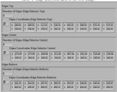
3 E x p e r i m e n t s c a r r i e d out 37 4 E d g e d e t e c t i o n d a t a of the left i m a ge 44
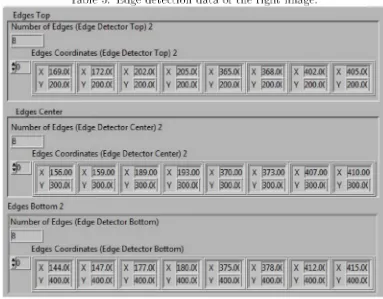
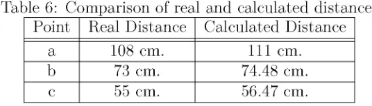
5 E d g e d e t e c t i o n d a t a of the r i g h t i m a g e 45 6 C o m p a r i s o n of real a n d c a l c u l a t e d distances 46
7 R u l e B a s e . 49 8 S u m of S q u a r e d E r r o r 50
P a r t I
1 Introduction
T h e m a i n objective of t h i s thesis is the i m p l e m e n t a t i o n of a n a u t o n o m o u s r o b o t t h a t is capable of f o l l o w i n g a r o a d w i t h the use of a stereocamera. T h e use of v i s i o n i n 3 D is a t r e n d i n m a n y v i s i o n a p p l i c a t i o n s , a n d we w o u l d like to a d o p t it for a u t o n o m o u s vehicle n a v i g a t i o n .
R o a d f o l l o w i n g requires t w o c r u c i a l steps: the r o a d r e c o g n i t i o n a n d the c o n t r o l of the speed a n d steering of the vehicle. T o r e a c h c o n t r o l l a b i l i t y i n these t y p e of r o b o t s i t is necessary to detect the r o a d a n d m a k e the i m a g e processing to c a l c u l a t e the m a n i p u l a t i o n s needed to keep the r o b o t i n the desired p o s i t i o n a n d p a t h .
It c a n be s a i d t h a t v i s i o n systems are a v e r y i m p o r t a n t factor i n the development of a u t o n o m o u s vehicles because t h e y are the sensors of the r o b o t ; therefore, the i m a g e processing needs to be done o n t i m e i n order to detect the r o a d a n d let the entire s y s t e m to be c o n t r o l l a b l e .
T h r o u g h t h i s thesis, various techniques i n different areas such as r o a d d e t e c t i o n , i m a g e processing a n d f u z z y c o n t r o l t h e o r y w i l l be e x a m i n e d i n order to achieve the objective.
1.1 Motivation
A u t o n o m o u s m o b i l e robots w i t h i m a g e processing u s i n g c o m p u t e r s are a challenge for the c o n t r o l s y s t e m due to the d e m a n d s i n c o m p u t a t i o n a l c a p a c i t y a n d also the a b i l i t y to do t h a t processing as fast as possible to a l l o w c o n t r o l l a b i l i t y of the vehicle. A u ¬ t o n o m o u s r o a d f o l l o w i n g has been researched t h r o u g h recent years because i t c o u l d prevent accidents i n real life s i t u a t i o n s a n d it is a t r e n d i n a u t o n o m o u s vehicle develop¬ m e n t . I n general, a u t o n o m o u s n a v i g a t i o n is a n i n t e r e s t i n g area to research because i t d e m a n d s real m e c h a t r o n i c s : electronics, m e c h a n i c s , c o m p u t e r p r o g r a m m i n g a n d c o n t r o l engineering.
1.2 Problem Statement and Context
A u t o n o m o u s m o b i l e r o b o t i c s b u i l d s p h y s i c a l systems t h a t c a n move p u r p o s e f u l l y a n d w i t h o u t h u m a n i n t e r v e n t i o n i n u n m o d i f i e d e n v i r o m e n t s a n d the development of tech¬ niques for a u t o n o m o u s n a v i g a t i o n c o n s t i t u t e s one of the m a j o r trens i n the current research o n r o b o t i c s . T h i s t r e n d is m o t i v a t e d b y the current gap between the available t e c h n o l o g y a n d t h e new a p p l i c a t i o n d e m a n d s . O n one h a n d , the techniques e m p l o y e d i n c u r r e n t i n d u s t r i a l robots l a c k the a b i l i t y to p r o v i d e flexibility a n d a u t o n o m y ; o n the o t h e r h a n d , there is a clear e m e r g i n g m a r k e t for t r u l y a u t o n o m o u s robots. P o s s i b l e a p p l i c a t i o n s i n c l u d e intelligent service robots for offices, h o s p i t a l s , a n d f a c t o r y floors, m a i n t e n a n c e robots for inaccessible areas, d o m e s t i c r o b o t s for c l e a n i n g or e n t e r t a n m e n t , or a u t o n o m o u s vehicles to help the d i s a b l e d a n d the ederly.
s i t u a t i o n s have to be considered, s u c h as: ways of d e t e c t i n g the r o a d a n d / o r obstacles, types of controls to be used a n d the i m p l e m e n t a t i o n of software a n d h a r d w a r e .
1.3 Solution Proposal
I n order to solve t h e p r o b l e m , it has b e e n d i v i d e d i n two m a i n areas: stereovision a n d f u z z y c o n t r o l .
1.3.1 S t e r e o v i s i o n
T o detect the r o a d a n d the obstacles, stereovision has b e e n p r o p o s e d to be the sensor of the vehicle because it does not o n l y detects objects i n t h e i m a g e , b u t also measures distances i n the frame.
1.3.2 F u z z y C o n t r o l
B e c a u s e the c o n t r o l a l g o r i t h m is also a f u n d a m e n t a l p a r t i n r o a d f o l l o w i n g for a s m o o t h ride a n d to reduce the error i n p o s i t i o n , f u z z y logic is p r e t e n d e d to be used as a n e m u l a t o r of h u m a n expertise, because it e x t r a c t s k n o w l e d g e of e x p e r t people a n d works w e l l w i t h i m p r e c i s e d a t a .
1.4 M a i n Contributions
T h e m a i n c o n t r i b u t i o n of t h i s thesis is the a l g o r i t h m of stereovision i m p l e m e n t e d to r o a d f o l l o w i n g . T h i s a l g o r i t h m , a l t h o u g h s i m p l e , is p r a c t i c a l for the objective need because it allows a fast processing of images, w h i c h is a v e r y i m p o r t a n t for the c o n t r o l l a b i l i t y of the a u t o n o m o u s vehicle. T h i s thesis is also the base for f u r t h e r w o r k , i n order to e x p a n d the a p p l i c a t i o n s a n d f u n t i o n a l i t y of t h i s study.
1.5 Thesis Structure
T h i s thesis shows the w o r k done i n order to solve the p r o b l e m . T h e thesis is s t r u c t u r e d as follows,
In c h a p t e r two, the t h e o r e t i c a l f r a m e w o r k is presented, a s u m m a r y of concepts t h a t are needed to u n d e r s t a n d w h a t is done i n n e x t chapters.
In c h a p t e r three, the state of art is presented, where s i m i l a r w o r k s are presented, w h i c h c a n be the base for t h i s thesis.
In c h a p t e r four, the p r o p o s a l for the s o l u t i o n is presented, i t i n c l u d e s the h y p o t h e s i s of h o w the objective c a n be c o m p l e t e d as best as possible as far as we are concerned.
In c h a p t e r five, the e x p e r i m e n t s w i t h the a u t o n o m o u s m o b i l e r o b o t are s h o w n ac¬ c o r d i n g to the objectives a n d also c o m p a r a t i v e s w i t h s i m i l a r w o r k s . T h e results of t h i s e x p e r i m e n t s is s h o w n as w e l l .
C h a p t e r 6 presents the conclusions of t h i s study.
2 Theoretical Framework
T h i s c h a p t e r shows the context over w h i c h t h i s thesis is based o n ; i n order to u n d e r s t a n d the objective of t h i s w o r k , the t h e o r e t i c a l f u n d a m e n t s have to be s t u d i e d . It is i m p o r t a n t to m e n t i o n the bases of r o a d f o l l o w i n g for a u t o n o m o u s vehicle n a v i g a t i o n w h i c h for t h i s thesis are b a s i c a l l y d i v i d e d i n : stereo v i s i o n , r o a d d e t e c t i o n a n d i m a g e processing, f u z z y c o n t r o l a n d r e a l - t i m e systems.
T h r o u g h t h i s chapter, the concepts of f u z z y c o n t r o l are s t u d i e d to u n d e r s t a n d the c o n t r o l l a b i l i t y of the a u t o n o m o u s vehicle. Stereo v i s i o n is also a f u n d a m e n t a l p a r t of the project, w h i c h i n t h i s case, is the sensor to detect the r o a d a n d the b o u n d a r i e s of the car; a n d i n order to sense, a n i m a g e processing of the v i s i o n s y s t e m has to be done.
2.1 Stereo Vision
A c c o r d i n g to [25], a n a r t i f i c i a l v i s i o n s y s t e m has:
• C a m e r a , captures the images a n d t r a s m i t t h e m as electric signals, f o l l o w i n g rules of e x p l o r a t i o n .
• Interface, it a d a p t s t h e electric signals p r o d u c e d b y the c a m e r a to the c o m p u t e r . • Software, i t allows to a n a l y z e the scenes a n d generates the c o m m a n d s for the
r o b o t c o n t r o l a u t o n o m o u s l y a n d i n r e a l t i m e ( A r t i f i c i a l Intelligence). F i g u r e 1 shows the c o m p o n e n t s of a n a r t i f i c i a l v i s i o n s y s t e m .
In t h e software p a r t , three consecutive phases c a n be d i s t i n g u i s h e d :
• S e l e c t i o n , of the useful a n d i n d i s p e n s a b l e i n f o r m a t i o n , because i t is a l m o s t i m -p o s i b l e to take i n t o account a l l the i n f o r m a t i o n the c a m e r a -provides.
• C a l c u l a t i o n s a n d g e n e r a t i o n , of the c o n t r o l orders to the m a n i p u l a t o r s , a c c o r d i n g to phase n u m b e r 2.
F i g u r e 2 shows the c o m p o n e n t s of software for a r t i f i c i a l v i s i o n s y s t e m .
F i g u r e 2: C o m p o n e n t s of software for a r t i f i c i a l v i s i o n systems
A c c o r d i n g to [42], the stereovision based c o n f i r m a t i o n consists i n four m a j o r steps: • d e t e r m i n a t i o n of regions of interest i n the stereoscopic images.
• a p p l i c a c i o n of a n u m e r i c a l z o o m to m a x i m i z e the d e t e c t i o n range. • c o m p u t a t i o n of a l o c a l d i s p a r i t y m a p i n the regions of interest.
• c r i t e r i o n e v a l u a t i o n f r o m t h i s d i s p a r i t y m a p to c o n f i r m the existence of a n obsta¬ cle.
F i g u r e 3: Stereo V i s i o n T r i a n g u l a t i o n
T r i a n g u l a t i o n requires k n o w i n g the focal l e n g t h of the c a m e r azyxwvutsrqponmlkjihgfedcbaZYXWVUTSRQPONMLKJIHGFEDCBA (f), the distance
between the c a m e r a bases (b), a n d the center of t h e images o n the i m a g e p l a n e (c1 a n d c2) . D i s p a r i t y (d) is the difference between the l a t e r a l distances to the feature p i x e l (v2 a n d v i ) o n the i m a g e p l a n e f r o m t h e i r respective centers. U s i n g the concept of s i m i l a r t r i a n g l e s , the distance f r o m the cameras (D) is c a l c u l a t e d as
2.2 Road Detection and Image Processing
V i s i o n - b a s e d r o a d d e t e c t i o n is a n i m p o r t a n t research t o p i c i n different areas of com¬ p u t e r v i s i o n s u c h as a u t o n o m o u s d r i v i n g , car c o l l i s i o n w a r n i n g a n d p e d e s t r i a n crossing d e t e c t i o n . [3]
S o m e basic concepts used i n i m a g e processing are:
• T h r e s h o l d : is a m e t h o d of i m a g e s e g m e n t a t i o n . F r o m a grayscale i m a g e , thresh¬ o l d i n g c a n be used to create b i n a r y images. D u r i n g the process, i n d i v i d u a l pixels i n a n i m a g e are m a r k e d as "object p i x e l s " i f t h e i r value is greater t h a n some t h r e s h o l d value a n d as a " b a c k g r o u n d " p i x e l otherwise.
• C o n t r a s t : is the difference i n v i s u a l p r o p e r t i e s t h a t makes a n object distinguish¬ able f r o m o t h e r objects a n d the b a c k g r o u n d .
B r i g h t n e s s : is a n a t t r i b u t e of v i s u a l p e r c e p t i o n i n w h i c h a source appears to be r a d i a t i n g or reflecting l i g h t . I n other words, brightness is the p e r c e p t i o n e l i c i t e d b y the l u m i n a n c e of a v i s u a l target. I n the R G B color space, brightness c a n be t h o u g h t of as the a r i t h m e t i c m e a n [i of the r e d , green a n d b l u e color coordinates:
2.3 Fuzzy Control
T h e controllers are the b r a i n of the r o b o t , t h e y do a l l the necesary c a l c u l a t i o n s so t h a t the r o b o t does w h a t is desired. I n t h i s case, the c o n t r o l l e r is r e q u i r e d to m a i n t a i n the m o b i l e at a c e r t a i n speed a n d p o s i t i o n . F u z z y logic was first designed to represent a knowledge expressed i n a l i n g u i s t i c or v e r b a l f o r m [21].
2 . 3 . 1 D e f i n i t i o n o f t h e F u z z y S e t s
A w a y to define a set is to e n u m e r a t e t h e i r elements, a n d the other, to use a f u n c t i o n zyxwvutsrqponmlkjihgfedcbaZYXWVUTSRQPONMLKJIHGFEDCBA
P(x), where every element x of the set has a p r o p e r t y P. A t h i r d w a y t h a t is to define a
set A u s i n g a c h a r a c t e r i s t i c f u n c t i o n . L e t A define the d o m a i n X. T h e n \iA : X — [0,1] is a c h a r a c t e r i s t i c f u n c t i o n of the set A i f every x
•
T h e g e n e r a l i z a t i o n of the t h e o r y of f u z z y sets is: the m e m b e r s h i p f u n c t i o n /ip of a f u z z y set F is a f u n c t i o n [ip : U — [0,1]
2 . 3 . 2 O p e r a t i o n s w i t h F u z z y S e t s
N o t i o n s like e q u a l i t y a n d i n c l u s i o n are two f u z z y sets d e r i v e d f r o m the classic t h e o r y of sets. T w o f u z z y sets are e q u a l if every element i n the universe has the same m e m b e r s h i p degree i n every one of t h e m . A f u z z y set A is a subset of the set B i f every element i n
the universe has a s m a l l e r degree of m e m b e r s h i p .
T h i s is a s i m p l e e x t e n s i o n of the classic o p e r a t i o n s . O t h e r possible extensions are, zyxwvutsrqponmlkjihgfedcbaZYXWVUTSRQPONMLKJIHGFEDCBA
iAns(x)= 1A(X) • is(x) orzyxwvutsrqponmlkjihgfedcbaZYXWVUTSRQPONMLKJIHGFEDCBA J A U B( x ) = min((1,jA(x) + 1B(x)) .
M o r e generally, t r i a n g u l a r n o r m s ( T - n o r m a n d S - n o r m ) are u s e d t o represent inter¬ s e c t i o n , u n i o n or c o m p l e m e n t .
2 . 3 . 3 F u z z y R e l a t i o n s
A r e l a t i o n c a n be c o n s i d e r e d as a set of o r d e r e d p a i r s . A s classic sets, classic r e l a t i o n s c a n be d e s c r i b e d b y a m e m b e r s h i p f u n c t i o n . S u p p o s e t h a t R is a r e l a t i o n of n order
defined i n X1 ...Xn t h e n JR = X1 ...Xn — [0,1] is a m e m b e r s h i p f u n c t i o n of the set
A for every X1 ...Xn,
2 . 3 . 4 O p e r a t i o n s w i t h F u z z y R e l a t i o n s
T h e t w o m o s t u s e d o p e r a t i o n s i n f u z z y r e l a t i o n s are i n t e r s e c t i o n a n d u n i o n . T h e s e are defined as follow: let R a n d S be b i n a r y r e l a t i o n s defines i n X x Y. T h e i n t e r s e c t i o n
b e t w e e n R a n d S is defined as
I n s t e d of m i n i m u m , a n y T - n o r m c a n be u s e d . T h e u n i o n of R a n d S is defined as
I n s t e a d of m a x i m u m , a n y S - n o r m c a n be used. T h e s e d e f i n i t i o n s c a n be e x t e n d e d t o a n y n u m b e r of r e l a t i o n s .
T h e c o m b i n a t i o n of f u z z y sets a n d f u z z y r e l a t i o n s is c a l l e d c o m p o s i t i o n a n d is defines as: let A be a f u z z y set defined i n X a n d R a f u z z y r e l a t i o n defined i n XxY. T h e n ,
the c o m p o s i t i o n A a n d R results i n a f u z z y set B defined i n Y is g i v e n b y
T h i s is the so c a l l e d m a x - m i n c o m p o s i t i o n . T h e m a x - p r o d c o m p o s i t i o n is defined as
2 . 3 . 5 A p p r o x i m a t e R e a s o n i n g
Inference i n a p p r o x i m a t e r e a s o n i n g is i n contrast to the inference i n classic logic. I n a p p o x i m a t e reasoning, the consecuence of a set given the f u z z y p r o p o s i t i o n s depends o n a esencial w a y i n the aggregate m e a n i n g to these f u z z y p r o p o s i t i o n s . T h e n , inference i n a p p o x i m a t e reasoning is the processing of f u z z y sets t h a t represent the m e a n i n g of
a c e r t a i n set of f u z z y p r o p o s i t i o n s . F o r e x a m p l e , given the m e m b e r s h i p f u n c t i o n szyxwvutsrqponmlkjihgfedcbaZYXWVUTSRQPONMLKJIHGFEDCBA JA
a n d JB , representing the m e a n i n g of a f u z z y p r o p o s i t i o n X is A a n d the m e a n i n g of the f u z z y c o n d i t i o n a l If X is A Then Y is B, the m e m b e r s h i p f u n c t i o n c a n be c o m p u t e d
representing the m e a n i n g of the c o n c l u s i o n Y is B.
2 . 3 . 6 I n f e r e n c e R u l e s
In a p p r o x i m a t e r e a s o n i n g , two inference rules are the most i m p o r t a n t . T h e inference c o m p o s i t i o n r u l e a n d the generalized m o d u s ponens. T h e first r u l e uses a f u z z y r e l a t i o n to e x p l i c i t i l y represent the c o n e c t i o n between two f u z z y p r o p o s i t i o n s , t h e second uses a r u l e I F - T H E N t h a t i m p l i c i t l y represents a f u z z y r e l a t i o n . T h e generalized m o d u s ponens has the inference s y m b o l i c scheme
where S i a n d S2 are s y m b o l i c names for l i n g u i s t i c v a r i a b l e s , a n d P1, P2, Q1 a n d Q2 are s y m b o l i c names for l i n g u i s t i c values. T h e rule of c o m p o s i t i o n for inference c a n be considered as a special case of generalized m o d u s ponens. T h e general s y m b o l i c f o r m is
where S1 RS2 is r e a d as " S1 s i n i n r e l a t i o n R to S2" a n d the m e a n i n g is represented as a f u z z y r e l a t i o n . T h e n , i n s t e a d of the I F - T H E N r u l e , there is a f u z z y r e l a t i o n R.
N o w t h e scheme of inference is considered,
where P a n d Q are f u z z y sets representing the m e a n i n g of P, Q a n d R are a f u z z y
r e l a t i o n defining the m e a n i n g of R , P is defined i n X a n d R over X x Y. T h e n the
c a l c u l a t i o n of the c o m p o s i t i o n a l r u l e of inference is done as
2 . 3 . 7 T h e I F - T H E N R u l e s
T h e r e are a n u m b e r of r e l a t i o n s t h a t c a n represent the m e a n i n g of I F X is A T H E N Y
is B. T h e most used i m p l i c a t i o n s i n f u z z y sets are:
I m p l i c a t i o n of L u k a s i e w i c z : T h i s i m p l i c a t i o n is based o n the equalivalence p — q ='
p V q. T o represent O R is also possible to use the l i m i t e d s u m min(l, 1zyxwvutsrqponmlkjihgfedcbaZYXWVUTSRQPONMLKJIHGFEDCBA — p + q) i n s t e a d
I m p l i c a t i o n of Z a d e h : I n logic of two values,zyxwvutsrqponmlkjihgfedcbaZYXWVUTSRQPONMLKJIHGFEDCBA p — q has the same t r u e values as
(pAq) V ' p. T h i s equivalence was used b y Z a d e h i n the next f o r m
2 . 3 . 9 I n f e r e n c e M a c h i n e
T h e r e are two ways to a t t a c k the design of the inference m a c h i n e of a f u z z y controller:
(1) inference b a s e d i n c o m p o s i t i o n a n d (2) inference based o n i n d i v i d u a l rules. T h e
basic f o r m of the inference m a c h i n e of the second t y p e is to c o m p u t e the general value of the o u t p u t v a r i a b l e i n i n d i v i d u a l c o n t r i b u t i o n s for each r u l e i n the base of rules. E a c h i n d i v i d u a l c o n t r i b u t i o n represents the values of the c o m p u t e d o u t p u t variables for each i n d i v i d u a l r u l e . T h e o u t p u t of the f u z z i f i c a t i o n m o d u l e , represents the a c t u a l values of the i n p u t variables a n d are p r o j e c t e d to each r u l e , a n d a c e r t a i n degree of equivalence is s t a b l i s h e d . E a c h degree of equivalence represents the degree of s a t i s f a c t i o n of a f u z z y p r o p o s i t i o n . B a s e d o n the degree of equivalence, the value of the o u t p u t v a r i a b l e i n the last r u l e is m o d i f i e d . T h e set of a l l the o u t p u t values of the equivalent rules represents the general value of the f u z z y o u t p u t . I n t h i s context, t h e design of p a r a m e t e r s for the inference m a c h i n e is:
• C h o o s e the r e p r e s e n t a t i o n of the m e a n i n g for a single r u l e , • C h o o s e the r e p r e s e n t a t i o n of the m e a n i n g for a set of rules, • C h o o s e the inference m a c h i n e ,
• P r o v e the set of rules to be consistent a n d complete.
I m p l i c a t i o n of M a m d a n i : W i t h respect to f u z z y c o n t r o l , t h i s is the most i m p o r t a n t i m p l i c a t i o n k n o w n i n the l i t e r a t u r e . Its d e f i n i t i o n is based i n the i n t e r s e c t i o n . T h e r e l a t i o n Rc (x of conjuction) is defined as
2 . 3 . 8 F u z z i f i c a t i o n ( F M )
A c c o r d i n g to [24], the f u z z y f i c a t i o n m o d u l e does the next f u n c t i o n s :
• F M - F 1 : D o e s a scale t r a n s f o r m a t i o n (input n o r m a l i z a t i o n ) t h a t m a p s the p h y s i c a l values of the i n p u t variables i n a n o r m a l i z e d universe ( n o r m a l i z e d d o m a i n ) . It also m a p s the n o r m a l i z e d value of the o u t p u t v a r i a b l e i n the p h y s i c a l d o m a i n . W h e n a n o r m a l i z e d d o m a i n is used, it is no necessary to use F M - F 1 .
2 . 3 . 1 0 D e f u z z i f i c a t i o n ( D M )
A c c o r d i n g to [24], the f u n c t i o n s of the d e f u z z i f i c a t i o n m o d u l e are:
• D M - F 1 : D o e s the so c a l l e d d e f u z z i f i c a t i o n t h a t converts the set of m o d i f i e d o u t p u t values to a single value.
• D M - F 2 : D o e s the d e n o r m a l i z a t i o n of the o u t p u t t h a t m a p s the o u t p u t p o i n t s i n the p h y s i c a l d o m a i n . D M - F 2 is not necessary if d o m a i n s not n o r m a l i z e d are used. T w o of t h e most used d e f u z z i f i c a t i o n operators are C e n t e r of A r e a a n d M e a n of M a x i ¬ m u m .
C e n t e r of A r e a : T h e m e t h o d of center of area or g r a v i t y center is the most k n o w n d e f u z z i f i c a t i o n m e t h o d . It is a l m o s t discrete, t h i s results i n
In t h e continues case, it is o b t a i n e d
M e a n of M a x i m u m : T h i s m e t h o d determines the first a n d last values wherezyxwvutsrqponmlkjihgfedcbaZYXWVUTSRQPONMLKJIHGFEDCBA Y has
a m a x i m u m degree of m e m b e r s h i p a n d t h e n i t takes the m e a n of those t w o values. F o r m a l l y ,
2.4 Real-Time Systems
D e a l i n g w i t h c o m p u t e r i m a g e processing is a c h a l l e n g i n g t a s k i n vehicle n a v i g a t i o n since h i g h n u m b e r of c o m p u t a t i o n s need to be done i n order to process the i n f o r m a t i o n f r o m the cameras a n d s t i l l have t i m e to c o n t r o l the vehicle a r o u n d the desired t r a j e c t o r y .
R e a l - t i m e c o m p u t i n g systems are systems i n w h i c h the i m p o r t a n c e of a n a c t i o n is not o n l y t h a t i t is done correct, b u t also the t i m e i t takes to be processed. I n order for tasks to get done at e x a c t l y the right t i m e , r e a l - t i m e systems must allow y o u to p r e d i c t a n d c o n t r o l w h e n tasks o c c u r [1].
A r e a l - t i m e s y s t e m m u s t d e m o n s t r a t e the f o l l o w i n g features: • P r e d i c t a b l y fast response to urgent events.
• H i g h degree of s c h e d u l a b i l i t y : the t i m i n g requirements of the s y s t e m m u s t be satisfied at h i g h degrees of resource usage.
2 . 4 . 1 R e a l - T i m e S c h e d u l i n g P o l i c i e s
T h e r e are different schemes for s c h e d u l i n g events. A c c o r d i n g to [1], some p o p u l a r r e a l -t i m e s c h e d u l i n g policies i n c l u d e :
• F i x e d P r i o r i t y P r e e m p i t v e S c h e d u l i n g : E v e r y t a s k has a fixed p r i o r i t y t h a t does not change unless the a p p l i c a t i o n specifically changes i t . A h i g h e r - p r i o r i t y t a s k p r e e m p t s a l o w e r - p r i o r i t y t a s k . M o s t r e a l - t i m e o p e r a t i n g systems s u p p o r t t h i s scheme.
• D y n a m i c - P r i o r i t y P r e e m p t i v e S c h e d u l i n g : T h e p r i o r i t y of a t a s k c a n change f r o m i n s t a n c e to i n s t a n c e or w i t h i n the e x e c u t i o n of a n instance, i n order to meet a specific response t i m e objective. A h i g h e r - p r i o r i t y t a k s p r e e m p t s a l o w e r - p r i o r i t y t a s k. V e r y few c o m m e r c i a l r e a l - t i m e o p e r a t i n g systems s u p p o r t such policies. • R a t e - M o n o t o n i c S c h e d u l i n g : A n o p t i m a l fixed-priority p r e e m p t i v e s c h e d u l i n g pol¬
i c y i n w h i c h , the h i g h e r the frequency of a p e r i o d i c t a s k , the h i g h e r its p r i o r i t y . T h i s p o l i c y assumes t h a t the deadline of a p e r i o d i c t a s k is the same as its pe¬ r i o d . It c a n be i m p l e m e n t e d i n a n y o p e r a t i n g s y s t e m s u p p o r t i n g fixed-priority p r e e m p t i v e s c h e d u l i n g or generalized to a p e r i o d i c tasks.
• D e a d l i n e M o n o t o n i c S c h e d u l i n g : A g e n e r a l i z a t i o n of the r a t e m o n o t o n i c s c h e d u l -i n g p o l -i c y -i n w h -i c h the deadl-ine of a t a s k -is a f-ixed p o -i n t -i n t -i m e relat-ive to b e g i n n i n g of a p e r i o d . T h e shorter t h i s (fixed) deadline, the h i g h e r its prior¬ ity. W h e n the deadline t i m e equals the p e r i o d , t h i s p o l i c y is i d e n t i c a l to the r a t e - m o n o t o n i c s c h e d u l i n g policy.
• E a r l i e s t - D e a d l i n e - F i r s t S c h e d u l i n g : A d y n a m i c - p r i o r i t y p r e e m p t i v e s c h e d u l i n g policy. T h e deadline of a t a s k i n s t a n c e is the absolute p o i n t i n t i m e b y w h i c h the i n s t a n c e must c o m p l e t e . T h e deadline is c o m p u t e d w h e n the i n s t a n c e must c o m p l e t e . T h e scheduler picks the t a s k w i t h t h e earliest deadline to r u n first. A t a s k w i t h a n earlier deadline p r e e m p t s a t a s k w i t h a l a t e r deadline. T h i s p o l i c y m i n i m i z e s the m a x i m u m lateness of anyset of tasks r e l a t i v e to a l l o t h e r s c h e d u l i n g policies.
3 State of A r t
I n t h i s chapter, r e l a t e d w o r k s are presented i n order to s t a b l i s h the context o n w h i c h t h i s thesis was based. T h e m a i n areas of s t u d y of t h i s thesis are: r o a d d e t e c t i o n u s i n g stereo v i s i o n a n d f u z z y c o n t r o l i n a u t o n o m o u s m o b i l e vehicles.
3.1 Road Detection with Stereo Vision
V i s i o n - b a s e d t r a j e c t o r y d e t e c t i o n is a v e r y i m p o r t a n t area of s t u d y because i t is a f u n d a m e n t a l p a r t i n a u t o n o m o u s d r i v i n g , car c o l l i s i o n w a r n i n g , object d e t e c t i o n a n d p e d e s t r i a n crossing d e t e c t i o n . D e t e c t i n g trajectories a n d roads w i t h v i s i o n systems c a n be done u s i n g m o n o c u l a r v i s i o n - s y s t e m s a n d stereo v i s i o n systems [15, 3]. P a r t i c u l a r l y , stereo v i s i o n has b e e n s t u d i e d l a t e l y because i t gives a n advantage over m o n o c u l a r v i s i o n systems: the measurement of d i s t a n c e , w i t h o u t the need of more sensors; therefore, we focus o n t h e research of stereo v i s i o n to detect the t r a j e c t o r y where the vehicle is d r i v e n . G r e a t interest has r e c e n t l y a r i s e n i n the design a n d development of a u t o n o m o u s l a n d vehicle [34, 35]. T w o of f u n c t i o n s of A L V ( A u t o n o m o u s L a n d V e h i c l e ) a u t o n o m o u s n a v i g a t i o n are the obstacle d e t e c t i o n a n d t h e robust d e t e c t i o n a n d t r a c k i n g of r o a d b o u n d a r i e s .
R o a d d e t e c t i o n is a c r u c i a l p r o b l e m for i n t e l l i g e n t vehicles a n d m o b i l e r o b o t s . It p r o v i d e s i n f o r m a t i o n a b o u t the w o r l d t h a t enables the i n t e l l i g e n t vehicle or r o b o t to i n t e r a c t w i t h its e n v i r o m e n t a n d react to events or changes t h a t influence its t a s k [44]. M a n y researchers have b e e n s t u d y i n g i t for several decades a n d d r a m a t i c development has b e e n a c c o m p l i s h e d , w h i c h c a n be categorized i n t o t w o m a i n types of m e t h o d s : v i s i o n - b a s e d m e t h o d s a n d L I D A R ( L i g h t D e t e c t i o n A n d R a n g i n g ) - b a s e d m e t h o d s . T h e stereovision makes possible to use o n l y cameras to d i r e c t l y measure range a n d color i n f o r m a t i o n , j u s t like h u m a n o p e r a t o r s . T h e r e f o r e , v i s i o n - b a s e d r o a d d e t e c t i o n is a v e r y i m p o r t a n t as w e l l as p r o m i s i n g b r a n c h i n the field [15]. A m o n g the c u r r e n v i s i o n -b a s e d m e t h o d s , some use m o n o c u l a r c a m e r a to e x t r a c t the r o a d r e g i o n -b y e m p l o y i n g features w i t h specific i n t e n s i t y , color a n d t e x t u r e w h i l e others use a b i n o c u l a r c a m e r a for r o a d d e t e c t i o n b y u s i n g 3 D s t r u c t u r a l i n f o r m a t i o n [15].
A v a r i e t y of m e t h o d s have b e e n p r o p o s e d for obstacle d e t e c t i o n . Several k i n d s of sensors are used to acquire i n f o r m a t i o n f r o m the e n v i r o n m e n t to c a r r y out r o b o t n a v i g a t i o n w i t h r e a l - t i m e obstacle avoidance. V i s i o n s y s t e m , 2 D or 3 D laser rangefinder a n d c o m b i n a t i o n s of t h e m are used to detect obstacles u n d e r different e n v i r o n m e n t . Stereo v i s i o n technique [43] was p o p u l a r l y used to detect obstacles for A L V . T h e m a i n p r o b l e m of stereo v i s i o n is t h a t c o m p l e x a l g o r i t h m has to be used to guarantee the correct p i x e l m a t c h i n g between t w o images. I n the past several years, the laser range m e a s u r e m e n t s y s t e m has been used to detect obstacle. I n [58], a n obstacle d e t e c t i o n s y s t e m for A L V u n d e r s e m i - s t r u c t u r a l e n v i r o n m e n t w i t h t w o 2 D laser range finders is d e s c r i b e d . 3 D L R F ( L a s e r R a n g e Finder)[38] a n d q u a s i - 3 D L R F [26] is u s e d for obstacle d e t e c t i o n i n c r o s s - c o u n t r y e n v i r o n m e n t a n d u r b a n e n v i r o n m e n t .
in figure 4.
Figure 4: Components of autonomous road following
3.1.1
Horizon Estimation
The horizon line is important information for knowing the area of interest in the image.
The road will be usually below the horizon line. To estimate the position of the horizon
line, an approach has been introduced by [32, 28, 52]. This method estimates the
horizon line by applying non-linear mixtures of linear regressors to the description of
an image obtained using gist descriptors [4]. Also, the horizon line can be easily detected
by detecting the road lines and extend them to know the point where those two lines
intersect; above that point, there is no information about the road, and below that
point is the area of interest. A vanishing point is computed at that intersection to
differentiate the road from the horizon gradually [3]. Figure 5 shows the horizon line
estimation according to [3].
Figure 5: Detection of the horizon line according to [3].
[image:25.612.114.529.459.618.2]3 . 1 . 2 O b s t a c l e D e t e c t i o n
W h e n d e a l i n g w i t h obstacles, there are a n u m b e r of ways to detect t h e m . O n e m e t h o d is to use r o a d - b a r r i e r s [37], a n o t h e r m e t h o d is to use u n c e r t a i n t y [53] a n d the p r i n c i p l e of color d e c l i v i t y [11].
A c c o r d i n g to [24], the obstacles c a n be classified as p o s i t i v e a n d negative. P o s i t i v e obstacles are tree t r u n k s , s a n d dunes a n d others t h a t e x t e n d out of the g r o u n d surface. T h e other t y p e are the negative obstacles, s u c h as ditches or holes, t h a t e x t e n d i n t o the g r o u n d plane. P o s i t i v e obstacles are detected b y a p p l y i n g a hysteresis t h r e s h o l d o n the m e a s u r e d t e r r a i n slope a r o u n d i m a g e p o i n t s a c c o r d i n g to [24]. N e g a t i v e obstacles are detected b y l o o k i n g for d e p t h j u m p s i n the range profile of a n i m a g e c o l u m n . I n order to follow roadside u n d e r various c o n d i t i o n , v i s i o n - b a s e d sensor a n d range-based sensors are used. I n [44], a n obstacle d e t e c t i o n m e t h o d integrates i n f o r m a t i o n f r o m laser rangefinder a n d c a m e r a to detect a n d t r a c k obstacles. In[3], a r o a d f o l l o w i n g m e t h o d integrates i n f o r m a t i o n f r o m laser rangefinder a n d c a m e r a to detect a n d t r a c k the r o a d b o u n d a r y . R o a d height, smoothness, color, a n d t e x t u r e were c o m b i n e d to y i e l d h i g h e r p e r f o r m a n c e of roadside.
3 . 1 . 3 3 D V i e w
A n o t h e r 3 D cue is the l a y o u t of the scene. T h e l a y o u t is a n a l y z e d u s i n g three m a j o r p a r t s of the image: (1) s k y p i x e l s , (2) v e r t i c a l surface pixels a n d (3) g r o u n d p i x e l s . W i t h these 3 D cues t h e r o a d is l i m i t e d to g r o u n d , n o n - s k y i m a g e regions. F u r t h e r , regions are a v o i d e d w h i c h are v e r t i c a l l y o r i e n t a t e d (i.e., b u i l d i n g s , vehicles, pedestrians or a n y o t h e r object present i n the scene). T h e s e g m e n t a t i o n of the i m a g e i n these 3 D cues is c o m p u t e d b y the m e t h o d p r o p o s e d i n [16]. R o a d d e t e c t i o n u s i n g scene l a y o u t is r o b u s t to different types of a s p h a l t s , lane m a r k i n g s a n d p e d e s t r i a n crossings. H o w e v e r , scene-l a y o u t for r o a d d e t e c t i o n m a y be sensitive to shadows as the a scene-l g o r i t h m uses s u p e r p i x e scene-l s e g m e n t a t i o n [3]. A n o t h e r i m p o r t a n t cue for d e t e c t i n g the r o a d is its 3 D geometry. T h i s r o a d geometry c a n be inferred u s i n g a scene (road) classification a l g o r i t h m where each class represents t y p i c a l 3 D r o a d geometries such as left t u r n , straight r o a d a n d j u n c t i o n s [30].
3.2 Fuzzy Control in Autonomous Mobile Vehicles
3.3 Comparison of Works
A c o m p a r a t i v e of t h e w o r k s i n t h e area h a s b e e n r e a l i z e d i n order t o p u t t h e w o r k done i n context. T a b l e 1 shows this c o m p a r a t i v e i n t h e last 6 years. T h e p a r a m e t e r s of d i f f e r e n t i a t i o n are, t h e t y p e of v i s i o n used, i f t h e w o r k i n c l u d e s d e t e c t i o n a n d / o r avoidance of obstacles, t h e t y p e of c o n t r o l i f used a n d i f there was a n i m p l e m e n t a t i o n of t h e s y s t e m .
T a b l e 1: C o m p a r i s o n of t h e different w o r k s i n recent years.
Year of Publication
Autor(sJ Title Vision Obstacle Control Implementation
2005 [19] Broggi, A.; Caraffi, C; Fedriga, R.Lj Grisleri, P.
Obstacle Detection with Stereo Vision for OIT-Road Vehicle Navigation
Stereo Detection None Yes
2006 [45] Seung-Hun Kim; Chi-Won R o h ; Sung-Chul K a n g ; Min-Yong Park;
A Hybrid Autonomous / Teleoperated Strategy for Reiiable Mobile Robot Outdoor Navigation
Mono
2006 [24] Cabani, I.; Toulminet, G.;
Bensrhair,zyxwvutsrqponmlkjihgfedcbaZYXWVUTSRQPONMLKJIHGFEDCBA A. A Fast and Self-adaptive Color
Stereo Vision Matching
Stereo None None No
2006 [43] Zezhong Xu; Yanbin Zhuang; Huahua C h e n ;
Obstacle Detection and Road Following using Laser Scanner
Lasser None None Yes
2006 [44] PerroUaz, M . ; Labayrade, R.; Royere, C . ; Hautiere, N . ; Aubert, D . ;
Long Range Obstacle Detection Using Laser Scanner and Stereovision
Laser/ Stereo
Detection None Yes
2007 [22] DubbeJman Obstacle Detection during Day and Night Conditions using Stereo Vision
Mono Detection None Yes
2007 [20] van d e r M a r k , W. j van den Heuvel, J.C.; G r o e n , F . C A ;
Stereo based Obstacle Detection with Uncertainty in Rough Terrain
Stereo Detection None Yes
2008 [50] Hong, D . ; Kimrael, S.; FJoehling, R. j Caraoriano, N. j Cardwell, W . ; Jannaman, G . ; Purcellj A . ; Ross, D.; Russel, E . ;
Development of a semi-autonomous vehicle operable by the visually-impaired
Stereo/ Laser/GPS
None None Yes
2008 [48] Neagoe, V . ; Tudoran, C.;
Road following for autonomous vehicle navigation using a concurrent neural classifier
Mono None Neural Classifier. Yes
2009 [21] Tiberiu Marita Barriers Detection Method for Stereovision-Based ACC Systems
Stereo Detection None Yes
2009 [46] Lid oris, G . ; Rohrmuller, F . ; W o l l h e n \ Dr;
Buss, M , ;
The Autonomous City Explorer (ACE) project — mobile robot navigation in highly populated urban environments
Laser Detection/ Avoidance
Behavior Selection,
Yes
2009 [9] Yi Fu; Li, H,; Kaye, M.
Design and Stability Analysis of A Fuzzy Controller for Autonomous Road Following
Mono None Fuzzy Yes
2010 [49] Das, A.; Naroditsky, 0.; Zhiwei Z h u ; Samarasekera, S.; Kumar, R.;
Robust visual path following for heterogeneous mobile platforms
Stereo None Follower Yes
2010 [47] Yi Fu ; Li, H . ; Kaye, M . E . ;
Hardware/Software Codesign for a Fuzzy Autonomous Road-Following System
Mono None Fuzzy Yes
2010 Hernandez, Aristeo.
Stereovision Feedback and Fuzzy Control for Autonomous Robot
Navigation-Stereo Detection/ Avoidance
[image:28.612.110.535.210.701.2]4 P r o p o s a l
I n t h i s c h a p t e r , the p r o p o s a l for s o l u t i o n is presented a n d the a l g o r i t h m t h a t was used i n order t o detect the r o a d , as w e l l as the m e t h o d for c o n t r o l i n g the car's d i r e c t i o n w i t h the f u z z y c o n t r o l l e r a n d the obstacle d e t e c t i o n t o stop the vehicle. T h e reasons for u s i n g each m e t h o d are e x p l a i n e d a n d some of t h e m , c o m p a r e d t o others i n order t o show b e t t e r p e r f o r m a n c e . T h e s o l u t i o n t o solve the p r o b l e m of t h i s thesis is presented i n t h i s c h a p t e r . F i g u r e 6 presents the i n d i v i d u a l c o m p o n e n t s t o solve the p r o b l e m .
4.1 Stereovision system
T h i s p a r t of the project is f u n d a m e n t a l , because the s t e r e o c a m e r a is the sensor of the r o b o t a n d the efficiency of the t o t a l s y s t e m depends o n the r e c o g n i t i o n of the r o a d a n d the i m a g e processing; the o u t p u t of t h i s process is the i n p u t of the f u z z y c o n t r o l l e r . T h e stereovision s y s t e m consists of t w o w e b c a m cameras t h a t are a l i g n e d t o be c o n s i d e r e d as a stereocamera. A stereo c a m e r a grabs v i d e o of a c e r t a i n scene b u t theres a n offset between the t w o images because of the different p l a c e m e n t of each c a m e r a . T h i s offset is c a l i b r a t e d a n d t h e n c o r r e l a t e d between the two cameras t o k n o w the d i s t a n c e of a n object i n the image.
4 . 1 . 1 I m a g e a c q u i s i t i o n
T h e i m a g e is a c q u i r e d b y t w o cameras p l a c e d i n front of the car. E a c h c a m e r a acquires the segment of the r o a d i n front of the r o b o t , b u t w i t h a n offset between t h e m . T h e grab a c q u i s i t i o n is c a l i b r a t e d so t h a t each frame i n each c a m e r a is t a k e n at the same t i m e t o process the i m a g e correctly. T h e interface w i t h the cameras is t h r o u g h U S B .
4 . 1 . 2 I m a g e p r o c e s s i n g
A f t e r a c q u i r i n g the t w o images, t h e y need to be processed to get the necessary i n f o r m a -t i o n -to recognize -the r o a d . F i r s -t , a -t h r e s h o l d is a p p l i e d -to -the o r i g i n a l i m a g e i n order to e l i m i n a t e noise a n d e m p h a s i z e the r o a d . T h e n , b r i g h t n e s s , contrast a n d g a m m a are e q u a l i z e d a c c o r d i n g to the scene to have a b e t t e r r e c o g n i t i o n of t h e r o a d lines. H a v i n g processed the i m a g e , the edge d e t e c t i o n is done, three lines are c o n s t a n t l y a n a l y z e d to detect the edges. W i t h the i n f o r m a t i o n of the edges detected, the p o i n t s a, b a n d
c are c a l c u l a t e d , w h i c h are the p a r a m e t e r s to c a l c u l a t ezyxwvutsrqponmlkjihgfedcbaZYXWVUTSRQPONMLKJIHGFEDCBA 9 a n dzyxwvutsrqponmlkjihgfedcbaZYXWVUTSRQPONMLKJIHGFEDCBA p . F i g u r e 7 shows t h i s p r o c e d u r e .
F i g u r e 7: F l o w c h a r t of the i m a g e processing.
T h e p o i n t szyxwvutsrqponmlkjihgfedcbaZYXWVUTSRQPONMLKJIHGFEDCBA ay, by a n d cy are c o n s t a n t , because t h e y are fixed coordinates t h a t are always checked. P o i n t s ax, bx a n d cx t h a t represent the center p o i n t of the r o a d , are used to c a l c u l a t e the slopes between a-b, a n d b-c. T h e slopes are converted to angles where a v e r t i c a l line represents 0 °. T h e difference i n angles between a-b a n d b-c shows the c u r v a t u r e of the r o a d . Slopes are c a l c u l a t e d as follows,
A n d to k n o w the angle 9 R , w h i c h determines the angle of c u r v a t u r e of the r o a d ,
T h e setpoint w i l l always be OR. T h e angle of the vehicle w i t h respect to the r o a d is 0v w h i c h is d e t e r m i n e d between the angle of the line b-c a n d the v e r t i c a l line. It c a n be p o s i t i v e or negative, a c c o r d i n g to the o r i e n t a t i o n of the vehicle w i t h respect to the r o a d .
p is c a l c u l a t e d as the p o i n t cx. T h i s way, it is a r e l a t i v e distance i n s t e a d of a fixed distance to the o r i g i n of the image because the p o s i t i o n i n g depends o n the o r i e n t a t i o n of the vehicle a c c o r d i n g to the r o a d at t h a t p o i n t . T h e setpoint for p is always 320,
F i g u r e 8: P o i n t s detected a n d c a l c u l a t e d i n the i m a g e processing
W h e n u s i n g a stereo c a m e r a , the p a r a m e t e r s for b o t h frames are c a l c u l a t e d as the average value of each p a r a m e t e r .
4.2 Fuzzy Controller
T h e f u z z y c o n t r o l l e r is the b r a i n of the r o b o t a n d the processing done determines the m a n i p u l a t i o n done to the a c t u a t o r s i n o r d e r to keep the vehicle i n the desired p o s i t i o n . T h e i n p u t s of the c o n t r o l l e r are •& a n d p, w h i c h are c a l c u l a t e d as s h o w n i n section 4.1 after the i m a g e processing a n d r o a d r e c o g n i t i o n .
I n the present w o r k , a f u z z y c o n t r o l l e r was developed to keep the car i n s i d e the r o a d a n d four l i n g u i s t i c variables were used: the angle of the car r e l a t i v e to the angle of the r o a dzyxwvutsrqponmlkjihgfedcbaZYXWVUTSRQPONMLKJIHGFEDCBA 9 a n d the distance f r o m the car's center to the r o a d center line p. T h e
i n the present development.
A c c o r d i n g to [23], the c o n t r o l rules are designed based o n e x p e r t knowledge a n d t e s t i n g . F u r t h e r m o r e , the c o n t r o l rules also meet the s t a b i l i t y requirements d e r i v e d
f r o m L y a p u n o v ' s direct m e t h o d . F o r e x a m p l e , i fzyxwvutsrqponmlkjihgfedcbaZYXWVUTSRQPONMLKJIHGFEDCBA p is + B a n d is i n c r e a s i n g r a p i d l y 9,
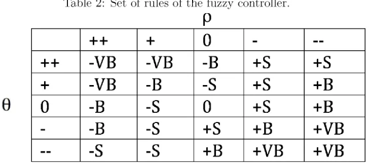
t h e n the vehicle s h o u l d t u r n left, i.e. 9S s h o u l d be + B . B a s e d o n t h i s k n o w l e d g e , we c a n o b t a i n t w e n t y five f u z z y rules. T a b l e 2 represents a b s t r a c t knowledge t h a t a n e x p e r t uses to c o n t r o l the steering angle given f r o m i n f o r m a t i o n a b o u t the error of 9 a n d p .
T h e i n p u t a n d o u t p u t l i n g u i s t i c variables are s u m m a r i z e d i n the t a b l e .
T a b l e 2: Set of rules of the f u z z y controller.
P
++
+
0
-
--++
- V B
- V B
- B
+s
+s
+
- V B
- B
-S
+s
+ B
0
- B
-S
0
+s
+ B
-
- B
-S
+s
+ B
+ V B
--
- S
- S
+ B
+ V B
+ V B
N o t e : V B : V e r y B i g ; B : B i g ; S: S m a l l ; 0: Zero.
In order to a p p l y the f u z z y c o n t r o l , 9 a n d p need to be d e t e r m i n e d ; these are c a l c u
[image:34.612.141.506.227.390.2]F i g u r e 9: F l o w c h a r t of the f u z z y controller.
F i g u r e 10: B l o c k d i a g r a m of t h e f u z z y logic controller.
T h e f u z z i f i c a t i o n p r o c e d u r e m a p s the crisp i n p u t values to the l i n g u i s t i c f u z z y t e r m s w i t h the m e m b e r s h i p values b e t w e e n 0 a n d 1. T h e f u z z i f i c a t i o n m e t h o d used is m a x
-m i n . I n t h i s thesis, we use five -m e -m b e r s h i p f u n c t i o n s for b o t h error i nzyxwvutsrqponmlkjihgfedcbaZYXWVUTSRQPONMLKJIHGFEDCBA p a n d error i n 9. F i g u r e s 11 a n d 12 i l l u s t r a t e the n o r m a l i z e d i n p u t m e m b e r s h i p f u n c t i o n s for p a n d 9
respectively.
F i g u r e 12: I n p u t m e m b e r s h i p f u n c t i o n s for error i nzyxwvutsrqponmlkjihgfedcbaZYXWVUTSRQPONMLKJIHGFEDCBA 9.
T h e d e f u z z i f i c a t i o n p r o c e d u r e m a p s the f u z z y o u t p u t f r o m the inference m e c h a n i s m to a crisp s i g n a l . It is used C e n t e r of S u m s as the d e f u z z i f i c a t i o n m e t h o d to c o m b i n e the r e c o m m e n d a t i o n s represented b y the i m p l i e d f u z z y sets f r o m a l l t h e rules. F i g . 13 shows the n o r m a l i z e d o u t p u t m e m b e r s h i p f u n c t i o n s . I n t h i s case, for faster c o m p u t a t i o n a l speed, the t y p e of m e m b e r s h i p f u n c t i o n s are c a l l e d singletons, each one has the value of 1.
4.3 Software Plataform
I n order to develop the code to integrate t h e stereovision s y s t e m a n d the f u z z y c o n t r o l l e r w i t h the h a r d w a r e , t h e use of the p r o g r a m L a b V I E W is p r o p o s e d m a i n l y because its h a r d w a r e i n t e g r a t i o n a n d the a b i l i t y to grab images f r o m t w o cameras of the same m o d e l t h r o u g h U S B . T h e d a t a display, c u s t o m controls a n d the user interface are also aspects a n a l y z e d to choose t h i s p l a t a f o r m for designing. A p p e n d i x B shows more a b o u t t h i s software p l a t f o r m a n d the a c t u a l code to i m p l e m e n t t h i s p r o p o s a l .
4.4 Hardware
5 Experiments and Results
I n t h i s c h a p t e r , a l l t h e e x p e r i m e n t s done i n order to prove t h e p r o p o s a l are presented. A l s o , t h e c o m p o n e n t s used, a n d t h e i n f r a e s t r u c t u r e of t h e project are s h o w n . I n t a b l e 3, a list of t h e e x p e r i m e n t s done a n d presented i n t h i s section is e x p l a i n e d .
T a b l e 3: E x p e r i m e n t s c a r r i e d out E x p e r i m e n t O b j e c t i v e
R o a d D e t e c t i o n T o recognize t h e r o a d a c c u r a t e l y i n different s i t u a t i o n s . D i s t a n c e C a l c u l a t i o n T o c a l c u l a t e t h e d i s t a n c e between t h e c a m e r a a n d t h e
different p o i n t s accurately.
O b j e c t D e t e c t i o n T o detect objects present o n t h e surface of t h e r o a d . C o n t r o l l a b i l i t y T o k n o w t h a t t h e car m a i n t a i n s its p o s i t i o n across t h e
r o a d .
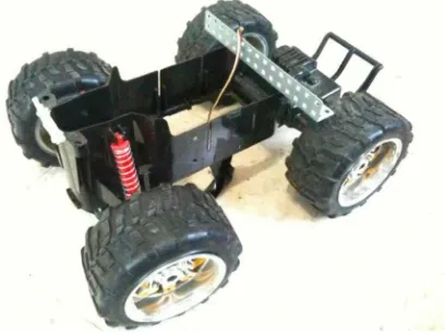
5.1 Hardware
[image:39.612.140.567.206.319.2]T h e r o b o t was b u i l t u s i n g a r e m o t e c o n t r o l car as a base, b u t t h e s t r u c t u r e was m o d i f i e d i n order to leave space for t h e a c t u a t o r s a n d sensors. B a s i c a l l y , o n l y t h e steering p a r t , a n d t h e wheels of t h e r e m o t e c o n t r o l car were used. T h e basic s t r u c t u r e is s h o w n i n figure 14.
[image:39.612.255.459.436.589.2]5 . 1 . 1 A c t u a t o r s
T h e m a i n a c t u a t o r s of t h e m o b i l e r o b o t are t w o servomotors a n d one D C m o t o r . O n e s e r v o m o t o r is a t t a c h e d to t h e steering s y s t e m , i n order to m o d i f y t h e steering angle a c c o r d i n g to t h e f u z z y c o n t r o l l e r o u t p u t . I n figure 15 t h e s e r v o m o t o r is s h o w n w i t h t h e steering s y s t e m .
F i g u r e 15: S e r v o m o t o r a t t a c h e d to t h e steering s y s t e m .
T h e other s e r v o m o t o r is used to m o d i f y t h e speed of t h e car. T h i s s e r v o m o t o r is c o n t r o l l e d to m o v e a c e r t a i n angle; t h e s e r v o m o t o r is c o u p l e d to a p o t e n t i o m e t e r t h a t regulates t h e i n p u t voltage of t h e m i c r o c o n t r o l l e r , w h i c h converts it i n t o a P W M s i g n a l t h a t regulates t h e voltage of t h e D C m o t o r i n order to speed it u p or d o w n . F i g u r e 16 shows t h e s c h e m a t i c d i a g r a m of t h i s c o n f i g u r a t i o n .
F i g u r e 16: S y s t e m t h a t regulates t h e speed of t h e r o b o t .
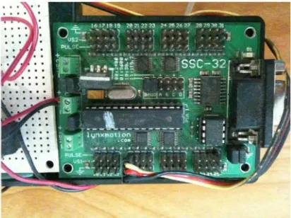
-m o t i o n . T h i s controller c a r d is able to -m a n i p u l a t e 32 different servo-motors, a l t h o u g h i n t h i s case, we use o n l y two. T h e c a r d c o m m u n i c a t e s to a c o m p u t e r t h r o u g h a serial cable. F i g u r e 17 shows the schematic d i a g r a m of the servomotor controller c a r d w i t h the servomotors.
I n order to c o n t r o l the speed of the car, a process needs to be done f r o m the ma¬ n i p u l a t i o n s i g n a l to the a c t u a t o r , w h i c h is a D C m o t o r m o u n t e d o n the rear wheels. F r o m the fuzzy c o n t r o l process, a m a n i p u l a t i o n s i g n a l is sent to the servo controller, i n order to c o n t r o l servo 1, t h a t moves p r o p o r t i o n a l l y to the desired speed. T h i s change i n p o s i t i o n is detected w i t h a p o t e n t i o m e t e r t h a t sends a r e g u l a t e d voltage between 0 a n d 5 V o l t s to the m i c r o c o n t r o l l e r . T h e m i c r o c o n t r o l l e r converts t h a t voltage i n t o a P W M s i g n a l t h a t is a p p l i e d to a t r a n s i s t o r T I P 3 1 C . A c c o r d i n g to the w i d t h of the pulse, the t r a n s i s t o r is t u r n e d o n a n d off w i t h a c e r t a i n frequency; a c c o r d i n g to t h e frequency, the D C m o t o r is p r o v i d e d w i t h a voltage between 0 a n d 9 V D C t h a t makes the car m o v e faster or slower. F i g u r e 18 shows the b l o c k d i a g r a m of t h i s process.
T h e steering s y s t e m w o r k s s o m e t h i n g like the speed c o n t r o l . F i r s t , the desired steering angle is c a l c u l a t e d i n the f u z z y controller. T h e m a n i p u l a t i o n needed to the d i r e c t i o n of t h e car is sent to t h e servo controller t h a t converts the s i g n a l i n order to m o v e the servo 2 as desired. B e c a u s e the servo 2 is a t t a c h e d d i r e c t l y to t h e steering s y s t e m , t h e wheels are m o v e d p r o p o r t i o n a l l y . F i g u r e 19 shows t h i s procedure.
F i g u r e 17: S e r v o m o t o r controller c a r d c o n f i g u r a t i o n .
[image:41.612.253.459.173.327.2]F i g u r e 19: B l o c k D i a g r a m of the S t e e r i n g S y s t e m .
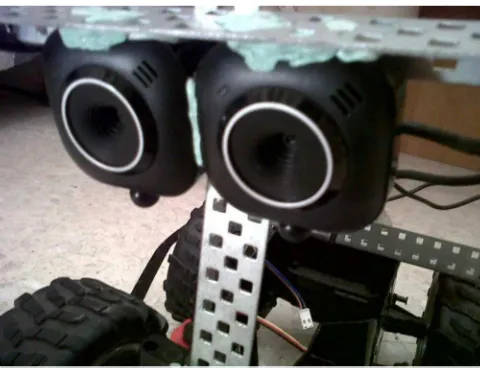
5 . 1 . 2 S e n s o r s
T h e a u t o n o m o u s m o b i l e r o b o t has t w o sensors. T h e s e are t w o w e b c a m s i n t e g r a t e d i n front of the car a n d p o s i t i o n e d p a r a l l e l t o each other to grab a v i d e o sequence to m a k e the stereovision a n a l y s i s . T h e w e b c a m s are t w o M i c r o s o f t L i f e C a m V X - 2 0 0 0 t h a t are able t o grab at 30 fps w i t h a r e s o l u t i o n of 640 x 480 p i x e l s . F i g u r e 20 shows the t w o sensors of the car.
F i g u r e 20: S t e r e o c a m e r a .
5 . 1 . 3 P r o c e s s i n g
[image:42.612.235.475.314.498.2]5.2 Image Processing and Road Detection
T h e a l g o r i t h m d e s c r i b e d i n section 4.1 was used to process the i m a g e g r a b b e d f r o m the s t e r e o c a m e r a a n d detect the r o a d .
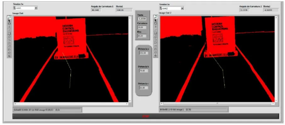
In figures 21-24, the results of the i m a g e processing are presented. E a c h i m a g e contains the left a n d right frames a n d the image of the r o a d . T h e s m a l l yellow p o i n t s represent the edge d e t e c t i o n i n each of the three lines a n d the y e l l o w lines represent the connections between a-b a n d b-c. B e t w e e n the t w o frames, the T h e t a a n d R h o of the s y s t e m are c a l c u l a t e d a n d the distance f r o m the s t e r e o c a m e r a to the p o i n t s a, b a n d c is s h o w n .
F i g u r e 23: F r o n t P a n e l of the vehicle o n a curve w i t h negative T h e t a .
F i g u r e 24: F r o n t P a n e l of the vehicle o n a curve w i t h p o s i t i v e T h e t a .
A c c o r d i n g to the results i n the screen, the r o a d is detected e x a c t l y as it is. T h e angle was m e a s u r e d a n d corresponds to the angle T h e t a specified i n the frame of each i m a g e .
A l s o p o i n t s a2 x,zyxwvutsrqponmlkjihgfedcbaZYXWVUTSRQPONMLKJIHGFEDCBA b2x a n d c2x were c a l c u l a t e d as follows,
A n d a c c o r d i n g to e q u a t i o n (1), the distances to the surface are c a l c u l a t e d .
T a b l e 5: E d g e d e t e c t i o n d a t a of the r i g h t i m a g e .
F i g u r e 25: R e s u l t s of the s i m u l a t i o n .
T o m a k e sure t h a t the distances c a l c u l a t e d are the real distance f r o m the c a m e r a to each p o i n t , the e x p e r i m e n t e x p l a i n e d i n C . 2 was c a r r i e d out. T h e results are presented i n t a b l e 6.
[image:47.612.127.510.100.399.2]T a b l e 6: C o m p a r i s o n of real a n d c a l c u l a t e d distances P o i n t R e a l D i s t a n c e C a l c u l a t e d D i s t a n c e
a 108 c m . 111 c m . b 73 c m . 74.48 c m . c 55 c m . 56.47 c m .
T a b l e 4 a n d 5 d e m o n s t r a t e t h a t the edges are detected correctly. because t h e r o a d is detected w i t h 4 lines i n t h a t case, w h i c h c o r r e s p o n d to 8 edges detected as i l l u s t r a t e d i n those tables.
A c c o r d i n g to t a b l e 6, i t c a n be c o n c l u d e d t h a t the m a x i m u m error i n c a l c u l a t i n g the distance is at p o i n t a, w i t h a 2.7% i n error. T h e best m a t c h is at p o i n t b, w i t h a 1.98% i n error. T h e error at p o i n t c is 2.6%. T a k i n g i n t o account t h a t the distances are c o m p a r e d w i t h the same c a l c u l a t e d distance i n case of a d e t e c t i o n of obstacle, the error i n t h i s distances doesn't influence the results, because t h e y are r e l a t i v e . B u t it c a n be s a i d t h a t for t h i s w o r k , a 2.7% i n error is g o o d e n o u g h to c o m p l e t e the objective.
T o i l l u s t r a t e the d e t e c t i o n of obstacles, figure 26 shows the p a i r of images w h e n no obstacle is detected.
F i g u r e 26: Image w h e n no obstacle is detected
[image:48.612.184.452.94.171.2] [image:48.612.93.549.358.541.2]F i g u r e 28: D e t e c t i o n of obstacle i n p o i n t b
[image:49.612.95.548.83.282.2]![Figure 5: Detection of the horizon line according to [3].](https://thumb-us.123doks.com/thumbv2/123dok_es/4457796.35691/25.612.133.505.114.231/figure-detection-horizon-line-according.webp)