Instituto Tecnológico y de Estudios Superiores de Monterrey
Campus Monterrey
Monterrey, Nuevo León a
Lic. Arturo Azuara Flores:
Director de Asesoría Legal del Sistema
Por medio de la presente hago constar que soy autor y titular de la obra
titulada"
", en los sucesivo LA OBRA, en virtud de lo cual autorizo a el Instituto
Tecnológico y de Estudios Superiores de Monterrey (EL INSTITUTO) para que
efectúe la divulgación, publicación, comunicación pública, distribución y
reproducción, así como la digitalización de la misma, con fines académicos o
propios al objeto de EL INSTITUTO.
El Instituto se compromete a respetar en todo momento mi autoría y a
otorgarme el crédito correspondiente en todas las actividades mencionadas
anteriormente de la obra.
De la misma manera, desligo de toda responsabilidad a EL INSTITUTO
por cualquier violación a los derechos de autor y propiedad intelectual que
cometa el suscrito frente a terceros.
Nombre y Firma AUTOR (A)
Visual Application Integration Through Web Services for
e-Services Hub-Edición Única
Title Visual Application Integration Through Web Services for e-Services Hub-Edición Única
Authors Javier Mijail Espadas Pech Affiliation ITESM-Campus Monterrey
Issue Date 2006-05-01
Item type Tesis
Rights Open Access
Downloaded 19-Jan-2017 11:07:47
INSTITUTO TECNOLÓGICO Y DE ESTUDIOS SUPERIORES
DE MONTERREY
Campus Monterrey
Graduate Program in
Electronics, Computing, Information and Communications
Visual Application Integration through Web Services for
e-Services Hub
THESIS
PRESENTED AS PARTIAL REQUIREMENT TO OBTAIN THE ACADEMIC DEGREE OF
Master in Science in Information Technology
BY
Javier Mijail Espadas Pech
INSTITUTO TECNOLÓGICO Y DE ESTUDIOS SUPERIORES DE
MONTERREY
Campus Monterrey
Graduate Program in
Electronics, Computing, Information and Communications
The committee members hereby recommended this thesis presented by Javier Mijail Espadas Pech to be accepted as partial fulfillment of the requirements for the Degree of Master in Science in Information Technology.
Committee Members:
___________________________ Ph. D. Guillermo Jiménez Pérez Thesis Advisor
___________________________ Ph. D. José Ignacio Icaza Acereto
__________________________ M.S. María Esperanza Garza Leal
__________________________________
Ph. D. David A. Garza Salazar
Director of Graduate Program in
Visual Application Integration through Web Services for
e-Services Hub
BY
Javier Mijail Espadas Pech
THESIS
Presented to Graduate Program in Electronics, Computing, Information
and Communications
This thesis is a partial requirement to obtain the Degree of Master
in Science in Information Technology
INSTITUTO TECNOLÓGICO Y DE ESTUDIOS
SUPERIORES DE MONTERREY
Dedicatorias
A Dios que todo lo hace posible
A mis padres, Freddy y Silvia, ejemplos de vida, lucha diaria y sobre todo, ejemplos de amor. Gracias por todo su apoyo y confianza. Los quiero mucho.
A mi hermana Nicte-Ha, porque puedo contar con ella en todo momento, la quiero mucho.
A Leydi, el amor de mi vida, sin ella nada de esto hubiese sido posible, ha sido mi gran apoyo en este largo camino. Gracias preciosa.
A mis abuelitos Rosa, Gilda, Benigno y Filiberto, que han luchado toda su vida para darme un ejemplo de esfuerzo y dedicación para salir adelante. Dios los bendiga.
Reconocimientos
A mi asesor, el Dr. Guillermo Jiménez, por haber compartido su conocimiento en este trabajo de tesis, por sus enseñanzas y esfuerzo dedicado. Muchas gracias.
A mis sinodales, el Dr. José Icaza y a la M.C. María Esperanza Garza Leal, por sus valiosos comentarios que hicieron de este documento un mejor trabajo.
Summary
An open platform named Hub is an infrastructure for deploy electronic services (e-services) in order to offer to Small and Medium Enterprises (SME) more opportunities in new global markets. The enterprises that contract the e-services in the Hub commonly have legacy applications or commercial information systems that must be integrated to the platform to form an heterogeneous system with the e-services implementation and external applications.
The conceptual architecture of the Hub is a service oriented approach and the use of new techniques of application integration as web services is needed for this kind of integration. Because the variability of legacy applications and the number of enterprises into the Hub, the manual integration (coding each case) is almost impossible.
This thesis proposes the elaboration of a visual tool prototype to integrate enterprise applications to a business process based infrastructure through distributed systems and application communication techniques known as Web services; and the use of automatic software generation. The main areas involved are the concept of e-services Hub, enterprise application integration, web services technologies and automatic code generation.
In order to reach an automatic integration this thesis proposes the use of software product lines. The idea of software product lines is to reduce both development time and cost. An applicative area of software product lines is generator technology, whose aim is the automatic production of software from a formal specification.
Contents
Dedicatorias ... iv
Reconocimientos...v
Summary... vi
Contents... vii
Index of Figures ... ix
Chapter 1 Introduction...1
1.1 Background...1
1.2 The PyME CREATIVA project...2
1.3 Problem definition ...3
1.4 Justification ...4
1.4.1 Need of integration ...4
1.4.2 Integration complexity...4
1.5 Hypothesis ...5
1.6 Goals ...5
1.7 Document Organization ...6
Chapter 2 Literature Review...7
2.1 Hub Architecture and e-Services ...7
2.2 Enterprise Application Integration ...10
2.3 Related projects...11
2.4 Service Oriented Architecture ...15
2.5 Supply Chain Integration...18
2.6 Software Generation ...21
2.7 Chapter Summary...25
Chapter 3 Analysis and Design of the Visual Integration Tool ...26
3.1 e-Services Hub Context ...26
3.1.1 E-Services Structure...26
3.1.2 Integration level ...27
3.2 Software Analysis ...28
3.2.1 Requirements ...28
3.2.2 Integrating through Web services ...29
3.2.3 Web services interfaces ...31
3.3.1 Architecture definition ...32
3.3.2 Tools and techniques ...34
3.4 Visual Tool Design ...35
3.4.1 Uses Cases ...36
3.4.2 Class diagrams...39
3.4.3 Interaction diagram...43
3.5. Implementation ...44
3.5.1 GUI for Visual Specification ...44
3.5.2 XML mapping as integration mechanism...45
3.5.3 Integration Code Generator...47
3.6 Chapter Summary...50
Chapter 4 Test Case for e-Supply service integration ...51
4.1 e-Supply Service overview...51
4.2 Process definition ...53
4.3 Defining the remote operations...55
4.4 Generating the integration code...56
4.5 Adapting the generated code...58
4.6 Chapter Summary...59
Chapter 5 Results and conclusions...61
5.1 Results...61
5.2 Conclusions ...64
5.3 Future work...66
5.4 Chapter Summary...67
Appendix A. XML files ...68
Appendix B. UML diagrams...74
Appendix C. Source codes...78
Bibliography ...87
Vita...90
Index of Figures
Figure 1.1 eServices Hub containing SME portals...3
Figure 1.2 Interface for information access ...4
Figure 2.1 eServices Hub architecture...8
Figure 2.2 Application integration problem domains ...10
Figure 2.3 Visual tool for AI in B2B ...12
Figure 2.4 Components of the EAI framework ...12
Figure 2.5 Information heterogeneity with XML integration ...13
Figure 2.6 Overview of the layer to build a B2B platform ...14
Figure 2.7 Service interfaces and implementation ...16
Figure 2.8 Service Oriented approach ...18
Figure 2.9 Architecture for a Supply Chain ...19
Figure 2.10 Architecture of an Integrated Supply Chain...20
Figure 2.11 Supply Chain Integration architectural approach ...20
Figure 2.12 Example of a Web Service broker...22
Figure 2.13 Example of Code Generator ...23
Figura 2.14 Configuration wizard’s architecture ...24
Figure 3.1. eService implementation within a portal platform...27
Figure 3.2. Hub architecture Application Integration ...28
Figure 3.3. Web services integration...28
Figure 3.4. Enterprise’s information domain...29
Figure 3.5. Application Integration through dynamic web services...30
Figure 3.6. Mechanism for integration through Web services ...30
Figure 3.7. Web services interfaces ...31
Figure 3.8. Retrieving of Web services interfaces ...32
Figure 3.9. Visual tool elements ...33
Figure 3.10. Service level integration ...34
Figure 3.11. Tools for the visual tool ...35
Figure 3.12. Interfaces of application integration tool...35
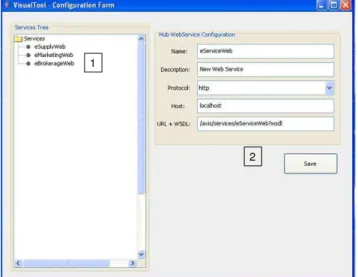
Figure 3.13. Introduction of configuration data ...36
Figure 3.14. Screen of configuration of generic Web services ...36
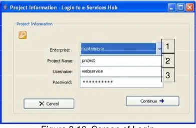
Figure 3.15. Login use case ...37
Figure 3.16 Screen of Login ...37
Figure 3.17 Web Service and Operation specification use case ...37
Figure 3.18 Screen of Web Service and Operation specification ...38
Figure 3.19 Code generation use case ...38
Figure 3.20 Screen for Code generation ...39
Figure 3.21. Main packages of the visual tool ...40
Figure 3.22 Visual Specification classes ...40
Figure 3.23 Data mapping classes...41
Figure 3.25 Interaction diagram ...43
Figure 3.26 Visual specification flow ...44
Figure 3.27 Code generator description...47
Figure 4.1 Simple supply chain workflow ...52
Figure 4.2 Workorders Web interface ...52
Figure 4.3 Report of dead times...53
Figure 4.4 A supply integration process ...54
Figure 4.5 Access to external application through web services ...55
Figure 4.6 Enterprise selection and login information ...55
Figure 4.7 Selection of getPurchaseOrders operation ...56
Figure 4.8 Code generation for getPurchaseOrders operation ...57
Figure 4.9 Application for report generation through Web services...58
Figure 4.10 Report of material usage...59
CHAPTER 1. INTRODUCTION
1.1 Background
Today, for a large number of companies, the information systems landscape is a complex mixture of old and new technologies (Linthicum, 2004). Linthicum has found that traditionally, companies built heterogeneous applications to support their operation in order for taking advantage of business opportunities within their organization. The typical approach is that enterprises develop their applications in an isolated way, with every department independently developing or acquiring their own applications and data storages. Currently, these companies confront the necessity of sharing information among those heterogeneous applications (commonly named legacy systems) and the new systems being developed. Linthicum (2004) has also observed that the Internet brought about an increased necessity for companies: the need of Web presence and integration of their systems.
As more and more organizations pursue the benefits of ebusiness, they are looking to a process called enterprise integration, or EI, as key technical enabler in transforming their business processes (Lam, 2004). A typical form of EI happens when a company wants to offer its existing products and services over the Internet, so it builds web frontend systems and integrate them to its backend legacy systems (any IT system already in operation).
A more complex EI scenario involves enterprise application integration. By this process, the organization links up previously separated and isolated systems to give them greater leverage.
An emerging EI scenario is business-to-business (B2B) integration (also called extended enterprise models), which occurs when an organization integrates its own business processes with those of its business partners to improve efficiency within a collaborative value chain (Lam, 2004). Examples of B2B applications include procurement, human resource, billing, Customer Relationship Management (CRM) and supply chains (Medjahed, 2003). In fact, effective and efficient supply chain integration is vital for the competitiveness and survival of organizations. With the emergence of the eBusiness era, supply chain needs to be able to extend beyond the traditional boundaries (Siau, 2004).
The need for supply chain integration techniques and methodologies has been increasing as a consequence of the globalization of production and sales, and the advancement of enabling information technologies (Ball, 2002).
automatic application integration by using Web services technologies within the PyME CREATIVA project (explained next). The tool provides visual specification facilities and capability of code generation to produce code for B2B integration of enterprises focused in supply chains.
1.2 The PyME CREATIVA project
The creation of industrial networks to foster the competencies of Small and Medium Enterprises (SME) requires the definition of new business models based on Internet availability. These networks need integrated electronic information services (eServices) that offer and enable coordination and cooperation among the different SMEs, allowing them to share their technological resources, thus creating virtual organizations (VOs). These eServices should be integrated into an easy to access open technological platform, easy to access, known as eHub or just ‘Hub’ (Molina, et, al. 2004).
A main goal in the PyME CREATIVA project (Program ICT4BUS, 2003) is to produce a low cost management and operational infrastructure for valueadded networks of SMEs. The Hub platform (Integrated eServices for Virtual Business) offers a variety of integrated eServices necessary for dynamic market competition. This eServices Hub can be seen as a marketplace platform, where SMEs can execute trading processes, issue purchase orders, get into supply chain management, issue request for quotations, and other types of business processes with other SMEs integrated to the Hub. In this project the following eServices are being developed and integrated within the Hub architecture (Molina, 2004):
• eSupply. Implements technologies for the integration of logistic services, industrial plant configuration, client/supplier relation management and supply chain tracking.
• eBrokerage. Integrates technologies to support the development of virtual organizations, enterprise industrial clusters, etc.
• eMarketing. Integrates different technologies for the development of customizable portals to promote products and services of the SMEs.
• eProductivity. Incorporates technologies for the diagnosis, planning, and monitoring of SMEs.
• eEngineering. Engineering collaboration that integrates design and manufacturing technologies for integrated product development.
Clients, suppliers
Internet
Internet
App Server
HTTP Server Others access
Corporative Portals
e-Services
Hub
SME portal SME portal SME portal SME portal SME portal Clients, suppliers
Internet
Internet
App Server
HTTP Server App Server Others access
HTTP Server Others access
Corporative Portals
e-Services
Hub
SME portal SME portal SME portal SME portal SME portal
Figure 1.1. eServices Hub containing SME portals [Adapted from (Molina, 2006)]
As shown by Figure 1.1, a number of SMEs will be integrated as clients or suppliers to this Hub by deploying their own web portal that will serve as an access point for its users to contracted eServices. The eServices Hub implementation pretends to integrate nearly 200 Mexican SME's for the first deployment (Program ICT4BUS, 2003). All the information will be introduced through web portals and the information processes will reside within the Hub platform.
SMEs need always maintain consistent and updated information of their core processes such as purchase orders, quotations, material stock, or customer contacts. As the number of SMEs interested in integrating their existent systems to Hub platform increases, it becomes necessary the implementation of mechanisms to integrate them to the Hub.
From its conceptualization and design, the Hub platform was considered as Service Oriented architecture. Also, the architecture defines that integration with external application should be achieved through Web services techniques (Molina, 2006). The Hub’s architecture (explained in detail in Chapter 2) defines external access from enterprise applications through a Service Oriented approach, in this case, Web services technologies. This kind of integration involves manual tasks that have to be designed and developed with specific requirements as data types, data sources or different information domain.
1.3 Problem definition
One of the aims of the PyME CREATIVA project is have at least two hundred thousands SMES with access contracted to the eServices in the Hub. Integrating hundreds of enterprises applications from SMES to the eHub following a manual approach is a task that seems inappropriate. However is something that should be performed unless something more elaborate could be think out.
The e-Services Hub needs to be integrated with external applications and internal services, using web services technologies. By now, these activities must be carried out in a manual way, which can consume considerable time and the possibility of errors. Considering and conciliating several data sources involves a meticulous and well-designed development tasks.
1.4 Justification
This research work is divided in two principal aspects based on the SME’s integration needs; the first one is in the need of integration, the second is the integration complexity.
1.4.1 Need of integration
The integration of existing systems in SMEs is a common need in the PyME CREATIVA project. A good example is when a legacy application or an ERP system must create a report of the work orders to check their status and update its produced quantity. If these work orders were introduced through e-Services interfaces at the web portal, the enterprise applications could not have access to this information. A web service interface could be implemented in order to achieve
Figu this kind of integration.
re 1.2. Interface for information access
Figure 1.2 shows the operation of this interface, where a legacy system can exe
.4.2 Integration complexity
Once that the need of integration is considered, another important aspect is the inte
• Number of enterprises within the Hub.
cute a remote method, implemented into the Hub platform, and get a list of the work orders in order to process them. Another explicit example, is a supply chain process, when a work order can be introduced at the Hub interface or at the legacy application, so, it is necessary that the information of this work order can be retrieved from the e-service by the enterprise systems.
1
• Diverse requirements of integration, data or access.
s.
The described scenario shows how manual application integration could bec
.5 Hypothesis
The integration of eServices Hub with external and internal applications thro
The hypothesis presumes that the development of a software tool to generate cod
Research questions
egration with the eServices Hub be achieved through
• a software generator wizard to generate the
• e generated (e.g., WSDL, Java,
• generate code with generic templates for different
• s of an interface for different applications?
.6 Goals
The main goal in this work is the design and development of a visual tool that allo
• Research about enterprise application integration and their technologies.
nts.
ntegration.
• Different and diverse applications to integrate.
• Dynamic increment in the number of enterprise
ome a complicated work. Manual integration requires creating composite application with almost all external applications. The goal in this thesis work is to integrate external applications with the complete functionality of the eServices.
1
ugh web services can be automated by using a software generator with a visual interface.
e for information sharing will constitute an easiest, faster and more reliable application integration approach, instead of manual integration, for the eServices Hub and SME’s systems.
• Can application int
web services technologies? Is it possible to implement
integration code for external applications? What kind of integration code needs to b other language)?
Is it possible to
programming languages? What are the characteristic
1
ws the automatic integration of the SME’s systems with the eServices Hub, integrating their legacy or commercial applications with the eServices functionality. The specific goals of this work are:
• Research code generation approaches.
• Define the common integration requireme
• Design the software architecture of the visual i
• Develop the software tool components.
The basic approach involves the use of web services technologies provided by the
.7 Document Organization
The present document is divided in five chapters.
The first chapter presents an overview of the PyME Creativa project and the e ser
d chapter includes a literature review of the main technological areas inv
The third chapter describes the design and development of the visual tool, inc
The four chapter analyses test cases for the visual tool functionality, presenting a b
The last chapter presents results and conclusions.
Hub platform. The tool will provide a visual interface to specify the correct end points and methods to get and set the data that the external application needs, then the tool will generate the necessary code to access the information.
1
vices Hub. Also it explains the problem and the need for application integration, and how this integration tool can help to generate automatically the code for application integration.
The secon
olved within this work, including enterprise application integration and similar projects related to application integration. Also it describes the main concepts used in this thesis like “service oriented architecture” including the web services technologies and software generation. It sets the conceptual base for the tool development process.
luding the conceptual software architecture, UML design diagrams as classes and use cases, and the component model of the software. Finally, it shows implementations of the main components.
usiness process that needs to be integrated with an eservice through web services, and describes how the visual tool can generate the necessary code and for application integration through web services mechanisms.
CHAPTER 2. LITERATURE REVIEW
This chapter presents the technologies involved to design and development of the software tool for the application integration of the SME systems with the e services Hub. It is described the software architecture of the Hub platform and its main technologies. A BusinesstoBusiness scenario is presented within the PyME CREATIVA project and its Hub implementation. Integration of information systems is depicted within the eServices contexts.
For this integration issues, is defined the Enterprise Application Integration as an approach to solve sharing data requirements between information systems. The Service Oriented Architecture (SOA) is a set of emerging technologies and XML standards used to build distributed systems through Internet protocols. The SOA technologies allow developing implementations for Application Integration.
As described in the previous chapter, the context of this research work resides in the PyME CREATIVA project, which plans to integrate small manufacturing enterprises within a technological platform. One of the most important services of this platform is a supply service with Supply Chain Management features, such as work orders tracking, material stock and production plant configuration. The integration of these functionalities with external application is the core target of the software tool proposed in this document. Due to this, the chapter describes the concept of Supply Chain Integration and its role in application integration and supply chains.
Finally, the last important technology is software generators, specifically configuration wizards, because the software tool should be able to build several software programs in agreement with input specifications and requirements of each system to integrate.
2.1 Hub Architecture and e-Services
The concept of creating Hubs is considered a “technological innovation” because it enables the integration of value added networks, creating virtual and smart organizations. This concept reduces critical troublesome that limits SME's competitiveness, allowing new business opportunities to be exploited and having access to new global markets. The Hub offers a variety of integrated eServices that are necessary for dynamic market competition. Innovation has three variants (Molina, 2006):
• eHub's (Engineering Hub's with Internet based services) Development, allowing SMEs to have access to a wide range of value added eServices.
• eServices implementation methodology, to demonstrate its impact and benefit for the SME through an integrated process to achieve competitiveness.
• Creation and demonstration of the new SME business model based on value added industrial networks that enable the creation of virtual and smart organizations.
An eService implementation could be defined as a composite component from a combination of user interfaces (views) and portlets (controllers) that interacts with the services stack (model) explained later. Another component is the BPM engine integrated to the portal platform to manage many workflows; it interacts with other components through its API (Application Programming Interface) and the services stack. The component that serves as broker of the entire platform is a services stack containing definition and implementation of applications, database connections, content management system, security, organization management, LDAP protocols, and other.
Figure 2.1 shows the Hub architecture, where the principal approach used is a serviceoriented architecture and a Business Process Management (BPM) in order to carry out the activities within the eServices. This platform includes a set of tools and frameworks to define, deploy and manage a number of electronic services. In Figure 2.1 is shown the components of this platform: Corporate Portal, BPM Engine, Web Service Bus (WSDL), Process Repository, File Repository, Collaboration Services and others.
Below this platform is the technological enterprise infrastructure that support the services stack consisting in collaboration services (P2P, SMTP, POP3), file repository, network services (FTP, SFTP), security (Kerberos, SSL), databases, etc.
The eServices Hub can be seen as a market place platform, where the SME can execute trading processes, purchase orders, supply chain management, request for quotations, and other types of electronic business (ebusiness) with others SME into the Hub.
Electronic commerce applications like eservices must support the interaction between different parties participating in a commerce transaction via the network, as well as the management of the data involved in the process. The Internet provides access to a large and diverse body of such applications. For the supplier’s viewpoint, the variety of available applications generates new business opportunities for providing new services by integrating, enhancing, or customizing existing commerce applications (Eyal, 2001):
• Comparative services are obtained by integrating several sources, providing the user with a uniform interface for posing requests.
• Integration of complementary services may also be a useful.
• Existing applications may also customized for special needs.
Unfortunately, the diversity of applications in each specific domain and the disparity of interfaces renders the integration and manipulation of applications a rather difficult task: application data (e.g. store catalogs, form attributes, orders information) may have different formats, making the collection and comparison of data complex. In addition, the application flow, the roles of the various actors participating in the applications, complication the coordination of activities performed in the component applications (Eyal, 2001).
The integration of this information with the eServices Hub should be possible, but is necessary to combine different technologies like Enterprise Application Integration (focusing in B2B integration), Service Oriented Architectures and Software Generation.
2.2 Enterprise Application Integration
BusinesstoBusiness (B2B) applications based on information systems’ interoperability are increasingly available over Internet. These emerging systems involve the exchange of both data and services among business information systems. They have created many challenges, including the need for novel interoperability techniques and architectures. Emerging B2B integration approaches must answer several questions: 1) how to process and share data in various business formats; and 2) how to integrate various business functionalities into Web services (Nicolle, 2003). For this purpose is described the Application Integration concept to solve diverse problems of systems integration and heterogeneous information.
Application Integration (AI) is a strategic approach for binding many information systems together, at both the service and information levels, supporting their ability to exchange information and leverage processes in real time. Application integration can take many forms, including internal application Enterprise Application Integration (EAI) or external application integration Businessto Business application integration (B2B). AI involves a combination of issues. Each organization and trading community has its own set of integration issues that must be addressed. Because of this, it is next to impossible to find a single technological solution set that can be applied universally. Therefore, each AI solution will generally require different approaches (Linthicum, 2004).
For example in Figure 2.2, a business process is represented as a set of steps to be accomplished. Every step may require information from different applications, and in some cases applications need to interact and share information with other applications or Web portals.
BusinesstoBusiness integration occurs when companies integrate their own business processes with those of their business partners to improve efficiency within a collaborative value chain (Lam, 2004). Examples of B2B applications include procurement, human resource, billing, Customer Relationship Management (CRM) and supply chains (Medjahed, 2003). In fact, effective and efficient supply chain integration is vital for competitiveness and survival of organizations and with the emergence of the eBusiness era, supply chain needs to be able to extend beyond the traditional boundaries (Siau, 2004).
Whether or not they follow these specific patterns, all of today’s ebusiness solutions draw heavily on AI requirements to integrate Webbased systems with each other and with heterogeneous middle and back end legacy systems belonging to the organization its business partners, or other service providers (Lam, 2004). According to (Lam, 2004) without a wellstructured, systematic approach, AI projects become dangerously unpredictable and risky. That is because in the IT industry exist the basic lifecycle processes for developing new systems (for example, the classic waterfall model and prototyping) but relatively few have structured approaches that can apply to AIintensive projects.
Interoperability is generally hampered by heterogeneity issues. Platform (hardware, software, communication) heterogeneity is resolved by communication standards and protocols such CORBA, IP and HTTP. Syntactic heterogeneity requires common or pivot metamodels to represents the data of the participating systems. Finally semantic heterogeneity, which difficult to tackle, requires semantic models and languages that can capture the meaning of the representation concepts of different information systems (Nicolle, 2003).
2.3 Related projects
A number of tools for application integration have been developed in order to satisfy specific needs in electronic commerce or businesstobusiness environments. These software tools allow the enterprises or platforms to integrate applications with different approaches and technologies.
Visual tool for AI in B2B (Juárez, 2001). This tool was created for SINCOe
Figure 2.3 Visual tool for AI in B2B [Adapted from (Juárez, 2001)]
As is seen in Figure 2.3, this visual tool applies the integration at the data level, at method level through a ORB (“Object Request Broker”) technology, in this case, CORBA, and at application execution level. By means of the visual integration tool uses the specification of operations to achieve the interaction between applications, object methods and data storages, and produces automatically the implementation code through a code generator.
XML Based Framework for EAI (Pendyala, 2003). This framework is a
template that can be applied repeatedly to different EAI situations. It suggests an open architecture and spans the four crucial areas for EAI: communication, data, process and monitoring.
UI
CRM Business
Logic XML interface
UI
Inventory Business Logic
XML interface
UI ERP Business
Logic XML interface
UI Billing Business
Logic XML interface
Integration Engine (translation and messaging)
Event Editor
Process Editor
Events repository
Process repository
EAI Portal
EAI Framework
The application integration architecture revolves around the envisaged framework. Figure 2.4 gives an overview of the components of the framework. As can be seen, the framework is XMLbased where the EAI is achieved through XML and related technologies, the components of the framework are (Pendyala, 2003):
a) A XML interface, which is part of the enterprise applications,
b) Enterprise Integration Engine, which handles the core functionality and, c) EAI portal, used to configure and define events and processes.
The XML interfaces of the applications handle DBMS to XML conversion and vice versa, while the Enterprise Integration Engine transforms XML data in one format to the other, based on the inputs statically generated from event and process editor.
JSP JDBC
DOM
Stylesheet CRM
vocabulary
DOM XSLT XML as event
XML
XML JDBC
Data Data
ERP vocabulary
Figure 2.5. Information heterogeneity with XML integration [Adapted from (Pendyala, 2003)]
The figure 2.5 shows the management of information heterogeneity of the framework. The design of the framework can be better described based on a scenario. For instance, is considered the scenario of a retail seller of consumer electronics, such as PC’s. When a new order comes in, the customer information is entered through a Customer Relationship Management (CRM) system interface. Purchase Order details and customer details are updated in the CRM database, by the CRM application. The framework extracts the product information from CRM database and generates corresponding XML mapping file. An AI Engine of the framework, driven by the XML process data generated by a process editor, it takes this XML file, transforms the required data fields and passes them over to the XML interfaces of other applications (Pendyala, 2003).
Through this approach (and technologies), is possible to generate a common information for several heterogeneous systems by accessing and retrieving data from different sources such as CRM, ERP and so on.
Toolkit for B2B Applications (Nicolle, 2003). This tool framework, called X
extensible metamodel and XML. It allows the creation of adaptable semantics oriented metamodels to facilitate the design of wrappers or reconciliators (mediators) by taking into account several characteristics of interoperable information systems such as extensibility and composability.
XTIMES defines a set of metatypes for representing metalevel semantic descriptors of data models found in the web. The metatypes are organized in a generalization hierarchy to capture semantic similarities among modeling concepts of interoperable systems. It is possible use the XTIME methodology to build cooperative environments for B2B platforms involving the integration of web data and services (Nicolle, 2003).
T1 T1 Tn
Integrated XML grammar
BNF + DL BNF + DL
A N
T1 T1 Tn
Integrated XML grammar
BNF + DL BNF + DL
A
A NN
Translator Compiler
Transformation Rule Builder Translation Layer
Strategic Hierarchy Builder Grammar Integration Layer
XEditor Specification Layer
Set of translators
Figure 2.6 Overview of the layer to build a B2B platform [Adapted from (Nicolle, 2003)]
Figure 2.6 depicts an example of B2B platform development using XTIME methodology. It consists of three layers: specification layer, grammar integration layer and translation layer. The specification layer allows local administrators to graphically describe local data model concepts and map them into Description Logic and BackusNaur Form (BNC) descriptions. The grammar integration layer is used to build the metamodel. It takes as input a set of description logic and BNF files of local systems and produces as output a metamodel in which the local concepts are mapped to metatypes and classified according to semantic similarities. The metamodel is represented as an XMLschema file. The goal of translation layer is to create data model translators to support information and service exchanges (Nicolle, 2003). The XTIME methodology can be applied to web services to classify and integrate the XML concepts defined in the Web Services Description Language.
CORBA (Common Object Request Broker Architecture) and DCOM (Microsoft technology) are component objects models for distributed systems and application interoperability.
A clear trend is the movement away from informationoriented to servicebased integration. Informationoriented integration provides an inexpensive mechanism to integrate applications because, in most instances, there is no need to change the applications (Linthicum, 2004).
2.4 Service Oriented Architecture
A newer technology for application integration is ServiceOriented Application Integration (SOAI), which allows enterprises share application services. Enterprises could accomplish this by defining application services they can share, and therefore integrate, or by providing the infrastructure for such application service sharing. Application services can be shared either by hosting them on a central server or by accessing their interapplication (e.g., through distributed objects or Web services) (Linthicum, 2004).
The recently middleware technologies for application integration, such as IBM Websphere, Microsoft .NET Framework, BEA WebLogic, and so on, are being focused in the Services Oriented Architecture, as solution to application integration problems. The SOA approach roots their concept in the web services technologies.
Software as service. An emerging approach linked to service oriented architectures is the Service Oriented Computing that is a computing paradigm that utilizes services as fundamental elements for developing applications/solutions (Papazoglou, 2003). The concept of software as a service espoused by SOC is revolutionary and appeared first with the ASP (Application Service Provider) software model. By providing a centrally hosted Intent application, the ASP takes primary responsibility for managing the software application on its infrastructure, using the Internet as the conduit between each customer and primary software application (Papazoglou, 2003).
It exposes its features programmatically over Internet using standard Internet and protocols, and
It can be implemented via a selfdescribing interface based on open XML standards.
Following is described deepest the web service concept and its actors over the service oriented approach.
Web Services. A Web service is a software system designed to support interoperable machinetomachine interaction over a network (Haas, 2004). Services are described by interfaces using a machineprocessable format (specifically WSDL). Other systems interact with the Web service in a manner prescribed by its description using SOAPmessages, typically conveyed using HTTP with XML serialization in conjunction with other Webrelated standards.
Basically, Web services are deployed on a collection of XMLbased standards that provide means for information passing between applications using XML documents. The loose coupling among applications is provided by Web services interfaces. The wide support of core Web services standards by major enterprise software vendors is the key reason why Web services technology promises to make application integration both within an enterprise and between different enterprises significantly easier and cheaper than before.
Figure 2.8. Service Oriented approach [Adapted from (Papazoglou, 2003)]
In a typical servicebased scenario a service provider hosts a network accessible software module (an implementation of a given service). Figure 2.8 depicts a service provider that defines a service description of the service and publishes it to a client or service discovery agency through which a service description is published and made discoverable. The service requester uses a find operation to retrieve the service description typically from the discovery agency, and uses the service description to bind with the service provider and invoke the service or interact with service implementation.
Technology necessary for SOA implementation relies on a common program toprogram communications model, built on existing and emerging standards such as HTTP, XML, SOAP (Simple Object Access Protocol), WSDL (Web Services Description Language) and UDDI (Universal Description, Discovery and Integration) (Kreger, 2001).
2.5 Supply Chain Integration
Because of the fact that PyME CREATIVA project pretends to integrate manufacturing SME’s with in the eServices Hub, one of the most important electronic service is eSupply for supply chain management. Then, it is important to define and describe the concept of Supply Chain Integration in order to identify technologies that allow the application integration in this context.
reduces costs (Siau, 2004). A fundamental ongoing endeavor of SCM is to foster information transparency that allows organization to coordinate supply chain interactions efficiently in dynamic market conditions (Singh, 2005).
Supplier R&D Logistics Operations Marketing and Sales Service Customer Suppl ie r Rel at ions hip Ma nage m
ent Products and services flow
Funds flow Information flow Customer Rel at ionshi p Mana ge me nt
Supplier R&D Logistics Operations Marketing and Sales Service Customer Suppl ie r Rel at ions hip Ma nage m
ent Products and services flow
Funds flow Information flow Customer Rel at ionshi p Mana ge me nt Suppl ie r Rel at ions hip Ma nage m
ent Products and services flow
different platforms, different terminologies, to achieve adaptive collaborations (Siau, 2004). Supplier’s Supply Chain System B2B Applications B2B Applications Customer’s Supply Chain System Individual Customer Other supply chain applications Database and operation management applications
Company’s Supply Chain System
Parts, Services Information Products, Services
Supplier’s Supply Chain System B2B Applications B2B Applications Customer’s Supply Chain System Individual Customer Other supply chain applications Database and operation management applications
Company’s Supply Chain System
Parts, Services Information Products, Services
RosettaNet interoperate at lower level of abstractions to reach this intra organizational information sharing, and they relay heavily on the definition of EDI like (Electronic Data Interchange) standards for the exchange of data, process knowledge, messages, etc (Ball, 2002).
For information sharing at the intraorganizational level, middleware components tie together the SCM system with factory ERP systems and retailer ERP systems. The middleware serves as an information backbone to transact and convert data among disparate ERP systems and SCM systems.
In the middlewarebased infrastructure, the message broker is use to implement distributed transactions and the integration manager is used for business processes execution (Britton, 2001). The middleware provides inter operational services such as transactions, shared directories, persistence, event handling, messaging and process execution based on standards, e.g. CORBA and DCOM (Ball, 2002). The protocol and data exchange language and format may come in many flavors including flat file, EDI, HTML and XML (Sokol, 1996).
2.6 Software Generation
It is wellknow that constructing software from available software modules can lead to higher productivity and quality than developing software from scratch (Jiménez, 2003). To reach a high reuse in software modules are defined the application families, which are groups of applications sharing characteristics but also exhibiting variability in their characteristics (Jiménez, 2003). An application family designed and implemented to take advantage of a common structure, common features, and prescribed variables characteristics is known as a software product line (Weiss, 1999).
At this point, it is important to mention that the software tool designed for this work is a code generator for an application family. The family has common features as application integration components or web services calls, but each generated program is different to other, because can be integrated with different eservices and calling different methods of the remote web services.
Wrapper Components. Although many legacy applications cannot be easily integrated into a software product line, one approach is to develop wrapper components (Gomaa, 2004). A wrapper component is a distributed application component that handles the communication and management of client request to legacy applications (Mowbray, 1997). A wrapper registers its service with the naming service so that it can receive client service requests.
<<network>>
aWebClient aWebService aWebService
Broker
Web client node Web service node Web service broker node
1: Web Service Discovery Request
3: Web Service
Request 4: Web Service
Response
1: Web Service Discovery Response
<<network>>
aWebClient aWebService aWebService
Broker
Web client node Web service node Web service broker node
1: Web Service Discovery Request
3: Web Service
Request 4: Web Service
Response
1: Web Service Discovery Response
Figure 2.12. Example of a Web Service broker [Adapted from (Gomaa, 2004)]
Consequently; wrapper components often interface to legacy code through crude mechanisms such as files, which might be purely sequential or indexed sequential files. The wrapper component reads or updates files maintained by the legacy application. If the legacy application uses a database, the database could be accessed directly through the use of database wrappers components that would hide details of how to access the database (Gomaa, 2004). For example, with a relational database, the database wrapper would use Structured Query Language (SQL) statements to access the database.
Developers can integrate legacy code into a componentbased application by placing a wrapper around the legacy code and providing an interface to it. The wrapper maps external requests from components in calls in the legacy code. The wrapper also maps external outputs from legacy code into responses to the component (Gomaa, 2004).
Code generators. Software system generators automate the development of software. Generators automatically transform compact, highlevel specifications of target systems into actual source code, and rely on libraries of parameterized, plugcompatible and reusable components for code synthesis (Batory, 1997). The primary benefit of any code generator is to reduce the amount of repetitive code that must be produced, thus saving time in the development cycle (Whalen, 1999). Another benefit to this approach is the ability to extend the services generated, enabling the code generator to act as a force multiplier for programmers. Having a code generator synthesize complex code dealing with concurrency, replication, security, availability, persistence and other services for each server object will ensure that all servers followed the same enterprise rules (Whalen, 1999).
Code Generator
Generator
Code
Specification
Specificator
Specification Access
DB
Domain
Processes Metadata Access
Configuration Access Code Generator
Generator
Code
Specification
Specificator
Specification Access
DB
Domain
Processes Metadata Access
Configuration Access
Figure 2.13. Example of Code Generator [Adapted from (Juárez, 2001)]
Also, by using a code generator, developers can experiment more rapidly with different architectures. Other benefit obtained when using a code generator for the data layer of enterprise architecture may be its ability to deal with evolving technology (Whalen, 1999). In the figure 2.13 is illustrated the relationship between a specification software and a code generator. This component system produces new adapted applications based in the output of specification subsystem (Juárez, 2001).
Generators are among many approaches that are being explored to construct customized software systems quickly and inexpensively form reuse libraries. CORBA, for example, and its variants simplify the task of building distributed applications from components; CORBA can simplify the manual integration of independently designed and standalone modules in a heterogeneous environment by generating proxys for client interaction with a server. Generators are closer to toolkits, objectoriented frameworks, and other reusedriven approaches because they focus on software domains whose components are not standalone, that are designed to be plugcompatible and interoperable with other components (Batory, 1997).
Configuration wizards. Two complementary concepts associated to application construction in a productline are configuration and composition. A
configuration consists in a set of features and their arrangement in defining an application; the set of modules implementing a specific configuration in a composition (Batory, 1998). How the modules can be composed to construct applications from configuration specifications could be determined at module design and implementation time.
An approach to build this configuration is presented by (Jiménez, 2003) in his productline development technique. This approach introduces the concept of
lines in wellunderstood domains. A configuration wizard is a tool for application specification and generation from prebuilt parameterized modules called wizlets. A
wizlet in a software module specifically designed and implemented to be composed with other wizlets using a configuration wizard as a tool to produce applications in a product line (Jiménez, 2003).
Wizlet repository
Domain knowledge Specification
interface Generator
Application
Wizlet repository
Domain knowledge Specification
interface Generator
Application
Figura 2.14. Configuration wizard’s architecture [Adapted from (Jiménez, 2003)]
Figure 2.15 depicts a generic architecture for a configuration wizard. Figure shows how the two parts in which is divided wizlet, are stored in two different containers: a wizlet repository storing the application code part, and the domain
knowledge repository containing the verification part of wizlets. A specification interface offers the application developer editing facilities to specify the application at hand. The generator receives application specifications from the developer; translates them to concise representations, verifies their semantic correctness and generates the application by adapting wizlets implementing specified requirements (Jiménez, 2003).
The specification interface of a configuration wizard displays a collection of domain features available to the application developer. A wizlet implements a feature and encapsulated semantic information describing its environmental requirements and constraints, and information describing to the wizlet environment. Also, the configuration wizard collects this information to produce the application, and compiles it into executable code (Jiménez, 2003).
At this point, the concept of configuration wizard has important influence for the software tool developed in this research work, because this tool has to implement the features of the configuration wizards. In the next chapter, is explained how the design of the software tool matches with the main components of a configuration wizard’s architecture.
2.7 Chapter Summary
In this chapter the architecture of the eServices Hub was analyzed together with the involved technologies to develop a software tool for application integration within the context of PyME CREATIVA project. Application integration is depicted in a B2B scenario and are described the integration needs by the Hub to communicate external application with the eServices of the project.
Enterprise Application Integration is introduced as an approach for data sharing between information systems. Service Oriented Architecture is presented as the context for developing implementation for Application Integration. The main concepts of Supply Chain Integration are introduced in order to exemplify how Application Integration can be applied in supply chain environments.
The visual tool described in the next chapter requires generate code for application integration. Concepts on code generators and how a software generator works are explained, specifically the configuration wizards technique.
CHAPTER 3. Analysis and Design
of the Visual Integration Tool
This chapter presents the design process of the software tool for application integration in the PyME CREATIVA project. The first section explains the structure of an eService within the Hub platform context and how these eServices are deployed and integrated into the Hub architecture. Also the section describes how the application integration should be made in order to access to the eServices business logic.
The second section describes the software architecture: the main components to be developed and their relationships. It also describes the tools and techniques used in the visual tool development. The third section details the software analysis process through UML diagrams, including the description of use cases and a set of class diagrams. The last section is an overview of the main components implementation depicting some parts of relevant code.
3.1 e-Services Hub Context
3.1.1 E-Services Structure
In order to present a solution for application integration with the electronic services presented in the last chapter, this thesis introduces the structure implementation of an electronic service (eservice) within the Hub platform. In general, eServices focus on providing services through the Internet. EServices have been viewed as Internetbased customer service and online account management services and alternately as an overarching servicecentric concept. Synthesizing various definitions, an eService is an integrated solution for customized functionalities that are delivered through the Internet (Kim, 2003).
The fundamental objective of eServices is clear: to have a collection of networkresident software applications accessible via standardized Web protocols (HTTP, HTTPS), whose functionality can be easily discovered and integrated into applications or composed to form more complex systems. At a fundamental level an eService is considered as an emerging confluence of three distinct technologies: (a) process description formalisms, including automata and workflow; (b) data management (including transforms, mediation, transactions), and (c) distributed computing middleware (Hull, 2003).
EService components are business modules that represent basic independent ebusiness service processes or functions such as authentication, authorization, advertisement, negotiation, and process integration (Kim, 2003).
For its implementation, each eService is composed by a set of components by using the eXo portal platform1 core API and components:
• A set of Java web components that contains user interfaces implemented with visual components named JavaServer Faces2. These user interfaces interact with the services stack and business rules engine through action listener classes.
• A set of user Web components that shows generic information of sessions, site maps, content, tasks, etc.
• A set of component services that implement views for different services of the platform, like organization service (add users, roles and memberships), workflow services (upload a new business process, cancel a running business process instance), or content management service (add, remove or edit user pages).
e-Serv
ic
e
Portlet JSF Components Portlet JSF Components Portlet JSF Components User Portlet User Portlet User Portlet Service Portlet Service PortletS e r v i c e
e-Serv
ic
e
Portlet JSF Components Portlet JSF Components Portlet JSF Components Portlet JSF Components Portlet JSF Components Portlet JSF Components Portlet JSF Components Portlet JSF Components Portlet JSF Components User Portlet User Portlet User Portlet User Portlet User Portlet User Portlet User Portlet User Portlet User Portlet Service Portlet Service PortletS e r v i c e Service Portlet Service Portlet Service Portlet Service Portlet S e r v i c e S e r v i c e
Figure 3.1. eService implementation within a portal platform Figure 3.1 depicts the components that must be implemented into an eService by using a portal platform with a Web container like eXo Platform. This eService implementation has a number of modules to develop, beginning with the business processes that must be modeled and deployed to interact with the business rules engine, following with the user interfaces (views) of the Web components by using JSF components and core components of the eXo platform. Another important issue to mention is that the access to these eServices is done through Web portals. That means, the interaction with the business logic of these applications uses Web pages and an Internet browser as access interface.
3.1.2 Integration level Since the conception of Hub architecture by (Molina, Et. Al, 2006) was a serviceoriented design in order to allow external applications, even mobile devices, to interact and integrate information to eServices deployed within Hub platform.
1 eXo Platform in an Open Source corporate portal and portlet container (http://www.exoplatform.com/) 2 JavaServer Faces (JSF) are a Java Specification Request (JSR-127) that defines a set of visual components
Figure 3.2. Hub architecture Application Integration
Figure 3.2 shows part of Hub architecture (explained in Chapter 2) where is conceived an external access to eServices implementations through Internet protocols. The principal idea is to provide additional functionality to be accessible through remote integration for external applications. To achieve this required integration it is possible to implement serviceoriented mechanisms like Web services technologies. The serviceoriented integration is done by defining application as accessible services by other applications. In the Chapter 2 was explained that concept in detail.
Figure 3.3. Web services integration
As the Figure 3.3 shows, the mechanisms should allow information’s access for each eService’s business logic. Such is the goal of this research work: a visual tool to generate the external integration with eServices in a service level.
3.2 Software Analysis
3.2.1 Requirements