ADVERTIMENT. La consulta d’aquesta tesi queda condicionada a l’acceptació de les següents
condicions d'ús: La difusió d’aquesta tesi per mitjà del servei TDX (www.tesisenxarxa.net) ha estat autoritzada pels titulars dels drets de propietat intel·lectual únicament per a usos privats emmarcats en activitats d’investigació i docència. No s’autoritza la seva reproducció amb finalitats de lucre ni la seva difusió i posada a disposició des d’un lloc aliè al servei TDX. No s’autoritza la presentació del seu contingut en una finestra o marc aliè a TDX (framing). Aquesta reserva de drets afecta tant al resum de presentació de la tesi com als seus continguts. En la utilització o cita de parts de la tesi és obligat indicar el nom de la persona autora.
ADVERTENCIA. La consulta de esta tesis queda condicionada a la aceptación de las siguientes
condiciones de uso: La difusión de esta tesis por medio del servicio TDR (www.tesisenred.net) ha sido autorizada por los titulares de los derechos de propiedad intelectual únicamente para usos privados enmarcados en actividades de investigación y docencia. No se autoriza su reproducción con finalidades de lucro ni su difusión y puesta a disposición desde un sitio ajeno al servicio TDR. No se autoriza la presentación de su contenido en una ventana o marco ajeno a TDR (framing). Esta reserva de derechos afecta tanto al resumen de presentación de la tesis como a sus contenidos. En la utilización o cita de partes de la tesis es obligado indicar el nombre de la persona autora.
WARNING. On having consulted this thesis you’re accepting the following use conditions:
Analysis of the dynamic behaviour of
rotating disk-like structures submerged
and confined
Doctoral Thesis
Presented to the Department of Fluid Mechanics of the
Technical University of Catalonia (UPC)
Presented by
Alexandre Presas Batllo
Under the supervision of
Professor Dr. Eng. Eduard Egusquiza i Estevez
and
Dr. Eng. Carme Valero Ferrando
September, 2014
Barcelona
CDIF
UPC
CDIF
CDIF
UPC
UPC
ACKNOWLEDGEMENT
Firstly, I want to express my gratitude to my thesis advisors Professor Dr. Eng. Eduard
Egusquiza and Dr. Eng. Carme Valero for their time, support and advices in the crucial
moments of my investigation. Without their continuous help, this work could not be
possible.
Thanks to Eng. David Valentin for our discussions during the last part of my thesis which
have helped to analyze the results obtained in this investigation. His work has made
possible to contrast experimental results obtained with numerical simulation.
Thanks to Dr. Eng. Xingxing Huang for his friendship and help in the first years of my
stay in the CDIF.
I want to have a special mention also for Paloma Ferrer and David Castañer of the CDIF
for their continuous help during my thesis.
Thanks also to the other members of the CDIF and of the department for their kind
treatment with me: Dr. Eng. Alfredo Guardo, Dr. Eng. Esteve Jou, Dr. Eng. Xavier Escaler
and Professor Dr. Eng. Eugeni Valencia.
This project would not have been possible without the financial and human support of
VOITH Hydro. I want to express my gratitude to Eng. Ulrich Seidel (Head of R&D Basic
Development) and his team for our helpful meetings during these years. Their conclusions
and advices after the meetings have been one of the main inspirations of this work.
Finally I want to mention the gratitude to my family, my girlfriend Laura and friends for
their company during these years. Special thanks to my friends Eng. Angel Claramunt and
Eng. Santiago Claramunt, with whom I shared very good and special moments at the begin
of my engineering studies.
SUMMARY
The analysis of the dynamic behaviour of rotating turbomachinery components is of
relevant interest to avoid damages or fatigue problems in these parts. To determine the
dynamic behaviour of a part of a structure it is necessary to perform an analysis of the free
vibration of this part and a study of the excitation characteristic. The free vibration analysis
(modal analysis) determines the natural frequencies and mode shapes of the structure. The
excitation analysis gives the frequency content and the shape of the excitation.
Hydraulic runners are very complex structures that are submerged and confined inside a
casing. Particularly pump-turbine runners behave as disk-like structures at their first modes
of vibration and they are excited with the well known Rotor-Stator Interaction (RSI) when
they are under operation. In order to study the effect of the rotation, the confinement and
the excitation on the dynamic behaviour of the structure in a systematic and clear way, a
simplified model is needed. For this reason, in this thesis the dynamic behaviour of a
rotating disk submerged in water and confined inside a casing has been analyzed
analytically, experimentally and contrasted with simulation.
Firstly, an analytical model for the analysis of the dynamic behaviour is presented. The
natural frequencies and mode shapes of a rotating disk considering the surrounding flow are
analytically determined with a simplified model. Also the response of the disk with
different excitation patterns that simulates the RSI is analyzed. Finally the transmission
from the rotating to the stationary frame is discussed.
For the experimental analysis a rotating disk test rig has been developed. It consists of a
rotating disk submerged and confined inside a casing. The disk has been excited from the
rotating frame with piezoelectric patches (PZT) and with a special impact device. The
response of the disk has been measured simultaneously from the rotating and from the
stationary frame.
The first several natural frequencies and mode shapes of the disk when it rotates in air
and in water have been obtained in the rotating frame with miniature accelerometers
screwed on the disk and contrasted with the analytical model presented and with a
numerical FEM simulation. Only the diametrical modes, which are the most relevant and
The disk has been excited with several rotating excitation patterns that simulate the real
RSI. The dynamic behaviour of the disk due to these excitation patterns has been
determined experimentally and contrasted with the analytical model.
Finally, the analysis of the transmission from the rotating to the stationary frame has
been performed. The natural frequencies and mode shapes of the disk have been detected
RESUM
L'anàlisi del comportament dinàmic de components rotatius en turbomàquines és de gran
interès per a evitar danys o problemes de fatiga en aquestes parts. Per determinar el
comportament dinàmic d'una part d'una estructura és necessari dur a terme una anàlisi de la
vibració lliure d'aquesta part i un estudi de la característica d'excitació. L'anàlisi de les
vibracions lliures (anàlisi modal) determina les freqüències i modes propis de l'estructura.
Amb l'anàlisi de l’excitació s’obté el contingut freqüencial i el mode de la excitació.
Els rodets hidràulics són estructures molt complexes que es troben submergides i
confinades dins d'una carcassa. Particularment els rodets de màquines turbina-bomba es
comporten com a estructures en forma de disc en els seus primers modes de vibració i estan
excitats amb la coneguda interacció rotor-estator (RSI) quan estan en funcionament. Per tal
d'estudiar l'efecte de la rotació, el confinament i l'excitació en el comportament dinàmic de
l'estructura d'una manera sistemàtica i clara, es necessita un model simplificat. Per això, en
aquesta tesi el comportament dinàmic d'un disc giratori submergit en aigua i confinat dins
d'una carcassa s'ha analitzat analíticament, experimentalment i contrastat amb simulació.
En primer lloc, es presenta un model analític per a l'anàlisi del comportament dinàmic.
Les freqüències i modes propis d'un disc giratori considerant el flux que l’envolta es
determinen analíticament amb un model simplificat. També s'analitza la resposta del disc
amb diferents patrons d'excitació que simulen la excitació RSI. Finalment es discuteix la
transmissió del sistema rotatiu al sistema estacionari.
Per a l'anàlisi experimental s'ha desenvolupat un banc de proves que consisteix d'un disc
giratori submergit i confinat dins d'una carcassa. El disc ha estat excitat des del sistema
rotatiu amb excitadors piezoelèctrics (PZT) i amb un dispositiu d'impacte especialment
dissenyat. La resposta del disc s'ha mesurat simultàniament des del sistema rotatiu i des del
sistema estacionari.
Les primeres freqüències i modes propis del disc quan gira en aire i en aigua s'han
obtingut des del sistema rotatiu amb acceleròmetres miniatura cargolats en el disc i s’han
contrastat amb les obtingudes amb el model analític presentat i amb una simulació
numèrica d’elements finits (FEM). Només els modes diametrals del disc, que són els més
El disc ha estat excitat amb diversos patrons d'excitació que simulen el veritable RSI. El
comportament dinàmic del disc a causa d'aquests patrons d'excitació ha estat determinat
experimentalment i contrastat amb el model analític.
Finalment, s'ha realitzat l'anàlisi de la transmissió des del sistema rotatiu al sistema
estacionari. Les freqüències i modes propis del disc s'han detectat amb diversos tipus de
RESUMEN
El análisis del comportamiento dinámico de componentes rotativos en turbomáquinas es
de gran interés para evitar daños o problemas de fatiga en estas partes. Para determinar el
comportamiento dinámico de una parte de una estructura es necesario llevar a cabo un
análisis de la vibración libre de esta parte y un estudio de la característica de excitación. El
análisis de las vibraciones libres (análisis modal) determina las frecuencias y modos
propios de la estructura. Con el análisis de la excitación se obtiene el contenido frecuencial
y el modo de la excitación.
Los rodetes hidráulicos son estructuras muy complejas que se encuentran sumergidas y
confinadas dentro de una carcasa. Particularmente los rodetes de máquinas turbina-bomba
se comportan como estructuras en forma de disco en sus primeros modos de vibración y
están excitados con la conocida interacción rotor-estator (RSI) cuando están en
funcionamiento. Para estudiar el efecto de la rotación, el confinamiento y la excitación en el
comportamiento dinámico de la estructura de una manera sistemática y clara, se necesita un
modelo simplificado. Por ello, en esta tesis el comportamiento dinámico de un disco
giratorio sumergido en agua y confinado dentro de una carcasa se ha analizado
analíticamente, experimentalmente y contrastado con simulación.
En primer lugar, se presenta un modelo analítico para el análisis del comportamiento
dinámico. Las frecuencias y modos propios de un disco giratorio considerando el flujo que
lo rodea se determinan analíticamente con un modelo simplificado. También se analiza la
respuesta del disco con diferentes patrones de excitación que simulan la excitación RSI.
Finalmente se discute la transmisión del sistema rotativo al sistema estacionario.
Para el análisis experimental se ha desarrollado un banco de pruebas que consiste de un
disco giratorio sumergido y confinado dentro de una carcasa. El disco ha sido excitado
desde el sistema rotativo con excitadores piezoeléctricos (PZT) y con un dispositivo de
impacto especialmente diseñado. La respuesta del disco se ha medido simultáneamente
desde el sistema rotativo y desde el sistema estacionario.
Las primeras frecuencias y modos propios del disco cuando gira en aire y en agua se han
obtenido desde el sistema rotativo con acelerómetros miniatura atornillados en el disco y se
numérica de elementos finitos (FEM). Sólo los modos diametrales del disco, que son los
más relevantes y similares a los de los rodetes hidráulicos, se han considerado en este
estudio.
El disco ha sido excitado con varios patrones de excitación que simulan el verdadero
RSI. El comportamiento dinámico del disco debido a estos patrones de excitación ha sido
determinado experimentalmente y contrastado con el modelo analítico.
Finalmente, se ha realizado el análisis de la transmisión desde el sistema rotativo al
sistema estacionario. Las frecuencias y modos propios del disco se han detectado con varios
INDEX
ACKNOWLEDGEMENT ... ii
SUMMARY ... iii
RESUM ... v
RESUMEN ... vii
INDEX ... ix
LIST OF FIGURES ... xiii
LIST OF TABLES ... xvi
NOMENCLATURE ... xvii
1. INTRODUCTION ... 1
1.1 Background and interest of the topic ... 1
1.2 State of the art ... 3
1.2.1 Free vibration of rotating disk-like structures ... 3
1.2.2 Excitation characteristic and dynamic behaviour of disk-like structures ... 5
1.2.3 Measurement from the stationary frame ... 6
1.3 Objectives ... 7
1.4 Outline of the thesis ... 8
2. ANALYTICAL MODEL ... 9
2.1 Analytical model for a rotating disk submerged and confined ... 9
2.1.1 Vacuum ... 10
2.1.2 Annular disk in contact with fluid that rotates with respect to the disk ... 11
2.1.3 Similarity to the rotating disk case ... 13
2.1.4 Simplified model in the averaged radius ... 13
2.1.5 Analogy to the modal model ... 19
2.2 Forced response of a system due to a multiple exciters under resonance ... 22
2.2.1 Model for general MDOF structures. Frequency response function ... 22
2.3 Rotor-Stator Interaction ... 23
2.3.1 Air ... 26
2.3.2 Water ... 27
2.4 Transmission to the stationary frame ... 28
2.4.1 Air ... 29
2.4.2 Water ... 30
2.4.3 Validity of the deduced transmission and analytical example ... 32
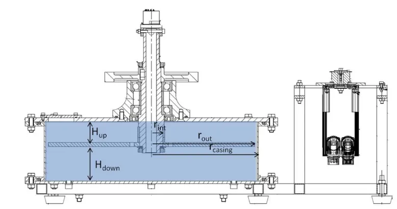
3. ROTATING DISK TEST RIG DESCRIPTION AND TESTS CARRIED OUT ... 35
3.1 Test rig ... 35
3.1.1 Disk ... 35
3.1.2 Casing ... 35
3.1.3 Motor ... 36
3.1.4 Slip ring ... 37
3.1.5 Data acquisition system ... 37
3.2 Instrumentation ... 37
3.2.1 Accelerometers ... 37
3.2.2 Piezoelctric patches (PZT’s) ... 38
3.2.3 Impact hammer ... 38
3.2.4 Laser ... 38
3.2.5 Presure sensors ... 38
3.2.6 Signal generator and amplifier ... 38
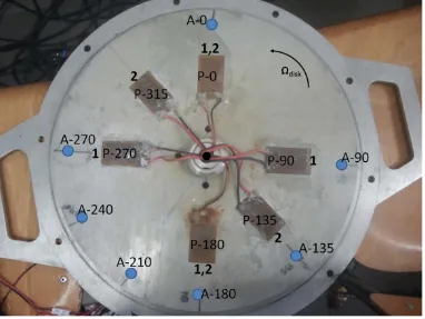
3.3 Position of the sensors ... 39
3.3.2 Stationary frame ... 40
3.4 Calibration ... 41
3.4.1 Accelerometers ... 41
3.4.2 Laser ... 41
3.4.3 Pressure sensors ... 42
3.4.4 Piezoelectric patches (PZT’s) ... 42
3.5 Tests to be performed ... 44
3.5.1 Excitation with hammer... 44
3.5.2 Excitation with one patch (sweep excitation) ... 44
3.5.3 Rotating excitation patterns with several PZT’s actuators for one configuration ... 46
3.5.4 Rowing accelerometer on casing for one configuration ... 49
4. STRUCTURAL RESPONSE OF A ROTATING DISK IN WATER ... 51
4.1 Preliminary analysis of the rotating disk in air ... 51
4.1.1 Natural frequencies of an annular plate in air... 51
4.1.2 Influence of rotation ... 54
4.2 Added mass of infinite water ... 56
4.3 Effect of the radial gap ... 56
4.4 Added mass of the disk confined ... 57
4.5 Effect of rotation in the natural frequencies ... 58
4.5.1 Experimental ... 58
4.5.2 Numerical simulation ... 63
4.5.3 Influence of the parameters through the analytical method ... 67
4.5.4 Comparison within methods ... 69
4.5.6 Comparison with air ... 73
4.6 Partial conclusions ... 74
5. DYNAMIC BEHAVIOUR OF THE ROTATING DISK IN AIR AND IN WATER . 76 5.1 Dynamic behaviour of the rotating disk in air due to an RSI excitation ... 76
5.2 Dynamic behaviour of the rotating disk in water due to an RSI excitation ... 79
5.3 Partial conclusions ... 81
6. DETECTION FROM THE STATIONARY FRAME ... 83
6.1 Detection of the disk natural frequencies in air ... 83
6.2 Detection of the disk natural frequencies and mode shapes in water ... 86
6.2.1 Laser ... 87
6.2.2 Pressure sensors ... 89
6.2.3 Accelerometers ... 92
6.2.4 Detailed response of the casing for one configuration ... 94
6.2.5 Influence of the casing ... 98
6.3 Partial conclusions ... 99
7. CONCLUSION AND FUTURE WORK ... 101
7.1 Conclusions and contributions ... 101
7.2 Future work ... 102
LIST OF FIGURES
Figure 2.1: Model of a totally confined disk with rotation of the flow ... 9
Figure 2.2: Rotor-Stator-Interaction ... 24
Figure 2.3:𝛾 = +2 pressure pulsations for a rotating disk. ... 25
Figure 2.4: Transmission from the rotating to the stationary frame ... 29
Figure 2.5: Analytical example ... 33
Figure 2.6: a)Forced response of the system. b) Angle between the response and the force34 Figure 3.1: Test rig without instrumentation ... 36
Figure 3.2: Casing of the test rig with the mounted sensors... 36
Figure 3.3: Experimental apparatus ... 39
Figure 3.4: Disk with installed accelerometers and piezoelectric patches ... 40
Figure 3.5: Sensors on the stationary frame ... 41
Figure 3.6: Polar plot of the sensors. a) Before calibration of PZTs b) After calibration of PZTS ... 43
Figure 3.7: Determination of the natural frequencies of the rotating disk. a) Time signals. b) Signals after FFT. c) FRF Amplitude& Phase ... 46
Figure 3.8: Excitation patterns created with the installed Piezoelectric Patches... 48
Figure 3.9: Detailed study of the transmission disk-casing. Position of the accelerometers and of the excitation points ... 50
Figure 4.1: Time signals of the sweep excitation (a) and response (b) ... 52
Figure 4.2: Autospectrum of the patch P-0 (a) and accelerometer A-0 (b) with peak hold method ... 53
Figure 4.3: Natural frequency n=±3 for different rotating speeds ... 54
Figure 4.4: Disk without water in the radial gap(a) and with water(b) ... 57
Figure 4.5: Sweep excitation (a). Non rotating case (b) and rotating case (6Hz) (c) ... 59
Figure 4.6: Normal mode shape (a). Complex mode shapes (b&c) ... 60
Figure 4.7: Polar plot of the accelerometers on the rotating disk. a) Ωdisk=0Hz,n=±2 ; b) Ωdisk=6 Hz,n=-2; c) Ωdisk=6Hz,n=2 ... 61
Figure 4.8: Phase of the sensors on the rotating disk for Ωdisk=6Hz ... 62
Figure 4.10: FEM model ... 64
Figure 4.11: CFD result. Obtaining Ωup-stat,r=r1 and Ωdown-stat,r=r1. Hup/rout=0.05 ... 66
Figure 4.12: Relation between Ωdisk and Ωup (black line) and Ωdown(red line). Hup/rout=0.05 ... 67
Figure 4.13: a) Effect of n in fcenter and b) effect of n in fn-neg-fn-pos ... 68
Figure 4.14: a) Effect of confinement in fcenter and b) effect of confinement in fn-neg-fn-pos ... 69
Figure 4.15: fcenter for n=2,3,4 ... 70
Figure 4.16:𝑓𝑛,𝑛𝑒𝑔 − 𝑓𝑛,𝑝𝑜𝑠 for n=2,3,4 ... 71
Figure 4.17: fcenter for a) Hup/rout=0.1.b) Hup/rout =0.15. c) Hup/rout =0.2 ... 72
Figure 4.18: 𝑓𝑛,𝑛𝑒𝑔 - 𝑓𝑛,𝑝𝑜𝑠Rfor a) Hup/rout=0.1.b) Hup/rout =0.15. c) Hup/rout =0.2... 73
Figure 4.19: Effect of the rotating speed of the disk in air and in water (n=±2) ... 74
Figure 5.1: Resonances around n=±2 (experimental) for the disk rotating in air (Ωdisk=8Hz). Different excitation patterns. ... 77
Figure 5.2: Resonances around n=2 and n=-2 (experimental) for the disk rotating in water (Ωdisk=8Hz). Different excitation patterns. ... 79
Figure 6.1: a) Excitation characteristic with one patch (PR-0) b) Response detected from the rotating system (AR-0) ... 84
Figure 6.2: a) Detection with pressure sensor (PRES-0) b) Detection with an accelerometer on the casing (AS-180) ... 84
Figure 6.3: Detection of the resonance with the Laser ... 85
Figure 6.4: Amplitude of the resonance with the peak hold method. a) Laser and AR-0 b)AS-180 ... 86
Figure 6.5: a) Excitation characteristic with a sweep excitation (PR-0) b) Response detected from the rotating system (AR-0) c) Response detected with the LASER ... 88
Figure 6.6: Amplitude of resonance of the modes n=3 and n=-3 with the accelerometer AR-0 and LASER ... 89
Figure 6.7: a) Response detected from the rotating system (AR-0) b) Response detected with the pressure sensor ... 90
Figure 6.9: a) Response detected from the rotating system (AR-0) b) Response detected
from the stationary frame (AS-180) ... 92
Figure 6.10: Amplitude of resonance of the modes n=3 and n=-3 with the accelerometer AR-0 (blue line) and AS-180 (red line) ... 93
Figure 6.11: Amplitude of the accelerometers on the stationary frame and phase with respect to accelerometer “AS-0” ... 94
Figure 6.12: Mode n=±2 detected from the casing. Ωdisk=0Hz ... 95
Figure 6.13: Mode n=±3 detected from the casing. Ωdisk=0Hz ... 95
Figure 6.14: Mode n= -2 detected from the casing. Ωdisk=8 Hz ... 96
Figure 6.15: Mode n=2 detected from the casing. Ωdisk=8 Hz ... 96
Figure 6.16: Mode n= -3 detected from the casing. Ωdisk=8 Hz ... 97
Figure 6.17: Mode n=3 detected from the casing. Ωdisk=8 Hz ... 97
Figure 6.18:a) Response of the casing due to an impact on the casing b) Response of the disk due to an impact on the disk ... 98
LIST OF TABLES
Table 2.1: Relative error (%) between natural frequencies in vacuum calculated with the
simplified model and the proposed model in [48] ... 15
Table 2.2: Natural frequencies and mode shapes of the analytical example ... 33
Table 3.1: Sensitivity of the Laser in air and in water ... 42
Table 3.2: Configurations tested ... 44
Table 4.1: Natural frequencies (Hz) of the disk in air ... 54
Table 4.2: First natural frequencies of the disk under different rotating speeds. ... 55
Table 4.3: Natural frequencies (Hz) of the disk in infinite water ... 56
Table 4.4: Natural frequencies (Hz) of the disk without and with water in the radial gap (numerical simulation) ... 57
Table 4.5: Natural frequencies (Hz) of the disk confined without rotation ... 58
Table 4.6: Natural frequencies (Hz) of the disk confined with rotation (experimentally) ... 62
Table 5.1: Amplification of the resonances (Aγ/A1-PATCH) of the rotating disk in air (Ωdisk=8Hz) due to the different excitation patterns. Analytical, experimental and error. ... 78
NOMENCLATURE
Disk parameters
hD rout rint ro Sup Sinf Thickness External radius Internal radius Averaged radius Upper surface Lower surfacew,wd Axial displacement of the disk
r,z,θ Cylindrical coordinates of the disk θ, θd, θr Angular coordinate rotating frame Ωrot, Ωdisk Rotating speed of the disk
ρD Density of the disk
D Bending stiffness
D* Parameter with units of bending stiffness
E,υ Young and Poisson modulus of the disk material
Tp *
Reference kinetic energy of the disk
Gaps disk-casing
Hup Upper gap disk-casing
Hdown Lower gap disk-casing
rcasing Radius of the tank
Flow parameters
Uup Potential function for the upper flow
Udown Potential function for the lower flow ϕup,ϕdown Potential function simplified
φup,θup Angular coordinate of the upper flow φdown,θdown Angular coordinate of the lower flow
Ωup Rotating speed of the upper flow
Ωdown Rotating speed of the lower flow
p Pressure
wf Axial displacement of the flow
Natural frequencies and mode shapes
n Number of nodal diameters
m Number of nodal circles
𝝎nm Natural frequency of the disk in vacuum
𝝎Fnm Natural frequency of the disk considering the surrounding fluid λnm Dimensionless natural frequency of the disk in vacuum
βnm AVMI factors
fnm Natural frequency expressed in Hz
Excitation characteristic
Zo Number of guide vanes
Zb Number of rotating blades
l,k Harmonics
γ Pressure pulsations
λ Arbitrary natural number
q Number of exciter
Nomenclature for the sensors
A-X, AR-X Accelerometer on the disk
P-X, PR-X Piezoelectric patch on the disk
AS-X Accelerometer on the casing
PRES-X Pressure sensor on the casing
LASER Laser sensor on the stationary frame
Abbreviations
CFD Computational Fluid Dynamics
FEM Finite Element Modelling
FSI Fluid Structure Interaction
PZT Piezoelectric actuator
Chapter 1
1.
INTRODUCTION
1.1
Background and interest of the topic
Dynamic problems in rotating components of turbomachinery are common. These
problems can reduce the life of these components drastically due to fatigue cycles or due to
a catastrophic failure after a short period of time [1-7]. To study the dynamic problems that
occur in these kinds of components both excitation and dynamic response of the rotating
part have to be studied in detail.
In turbine and pump impellers, the excitation characteristic under operation is the
superposition of several frequencies, which are harmonics of the rotating speed of the
machine. The harmonics that are excited depend on the number of rotating blades and
number of guide vanes on the stationary part of the machine. The combination of rotating
blades and guide vanes determines also the excitation shape. This kind of excitation, which
is known as Rotor Stator Interaction (RSI), is well studied in many references [5, 8-10].
While the excitation is well characterized by analytical, experimental and numerical
simulations, the dynamic response of impellers, especially when they are submerged and
rotating, has not been deeply studied. To study the structural response of the impeller
means to determine the natural frequencies, damping and associated mode shapes of the
free vibration of the structure. This response has been well determined for impellers that are
rotating in a low density medium, such as air[11, 12].
Nevertheless, for hydraulic impellers that are submerged in water, the influence of
rotation on the natural frequencies has not been published yet. Some studies determine the
added mass effect of still water on the natural frequencies [13-15]. Although the influence
of still water and confinement is considered, the real operating condition of hydraulic
runners, i.e. submerged, confined and rotating is not considered in these studies. To
calculate the added mass effect of the surrounding water in this condition, the flow pattern
FSI (Fluid-structure-interaction) problem has to be solved considering the structure and the
fluid, which is a difficult task to be done analytically or numerically. Also the experimental
measurement on prototypes is complicated, since the runner is inaccessible. Due to all the
mentioned problems and in order to understand the effects of the rotation clearly, simplified
models are needed.
An appropriate simplified model of some kind of hydraulic runners is a disk, due to the
similarity of the first mode shapes of these components with the mode shapes of a disk
[14]. There are many studies of rotating disks in air [16-20], but few of them for disks
rotating in water [8, 21]. In [8] an analytical method to calculate the added mass effect of
the rotating fluid in one side is given but without numerical results. Recently [21], conduct
experiments with a stationary disk and water that is forced to rotate with respect to the disk.
In this case, experimental results were provided but they were not contrasted with an
analytical model or numerical simulation. Furthermore, in both mentioned cases the disk is
considered stationary with the surrounding water on one side that rotates with respect to it.
Nevertheless, in the real case the impeller, which is a disk-like structure, is the part that
rotates inducing a water rotating flow in the upper and lower part of the structure.
Finally, since the rotating parts of the machine are usually inaccessible, it is desirable to
measure their response with sensors located on the stationary frame. In this case, it has to
be considered that the structural response of the rotating disk-like component viewed from
the stationary frame leads to frequency shifts that depend on the rotating speed and on the
mode shape [16].
Therefore, to study experimentally the effect of rotation on the natural frequencies of
the rotating disk-like structure and the effect of rotation on the detection of these natural
frequencies when analyzed from the stationary frame, it is necessary to develop a rotating
disk test rig, that can be excited and its response measured from both, stationary and
1.2
State of the art
1.2.1
Free vibration of rotating disk-like structures
The vibration of rotating disk-like structures has been studied extensively in the last
years due to their relevance in real engineering applications such as circular saws, cutters,
hard disks or turbomachinery components. Particularly in hydraulic turbomachinery,
runners are disk-like structures which are submerged and confined rotating in water.
First studies on rotating disks were developed by Campbell [22]. In this study he
introduced the term critical speed, at which a standing wave appears on the disk. The effect
of rotation in the dynamic behavior of the disk was introduced by Lamb and Southwell
[23]. Their study was focused on a disk, which rotate about its center with constant angular
velocity. Southwell [24] studied the vibration of circular disks clamped at its center. He
considered the effect of a shaft that clamps the disk at its center, in the natural frequencies
of the rotating disk. This effect was not considered in the previous study. Later studies [18,
25, 26] determined other effects using numerical simulation. In [25] Jin Wook Heo studied
the effect of misalignment in the natural frequencies of the disk. Bauer [18]studied the
effect of the attachment to the stationary part. Finally in [26], L.Pust studied bladed disk
with imperfections. Although, these studies provides a good knowledge on the dynamic
behavior of rotating disks, the surrounding fluid has not been considered, since in these
cases this fluid was air, which has no relevant effects on the dynamic behavior of the
rotating disk.
The effect of a high density surrounding fluid (such as water) in the vibration
characteristics of simple structures has been considered in many cases. Assuming an
infinite fluid domain, Kwak in [27]studied the hydroeleastic vibrations of circular plates.
Nevertheless, the effect of nearby rigid walls, which is a very common situation in real
applications, was not considered. This problem was studied firstly by Lamb [28]. He
considered the contact plate-water in only one side and located in a hole of an infinite rigid
wall. C.Rodriguez [29] and C.Harrison [30] studied the influence of only one nearby rigid
wall in the natural frequencies of a cantilever plate. They both concluded that the distance
plate-wall has a great influence on the added mass effect; i.e. the natural frequencies of the
immersed and confined plates, which makes the problem much more complex, has been
studied recently. In [31] Askari studied a circular plate submerged in a rigid cylindrical
container. He provided a very complete formulation for the flow above and under the disk.
The influence of the radial gap and the influence of the free surface in the natural
frequencies was also investigated. Numerical results were validated with experimentation
in this study. Although the influence of the surrounding fluid, the nearby rigid walls and the
free surface in the hydroelastic vibration of plates has been considered in the mentioned
cases, none of them investigates the effect of the rotation of the surrounding water.
The effect of a fluid field rotating with respect to the vibrating plate on the natural
frequencies is very complex to study analytically, numerically and experimentally.
Nevertheless, this effect has to be considered to describe the real boundary condition in the
case of hydraulic turbomachinery. Kubota in [8] investigated this problem. He proposed a
model to study the effect of rotation in the natural frequencies of a rotating disk in water.
Departing from a simplified Equation for the disk structure and for the fluid potential in the
tank, he deduced the effect of a fluid field rotating with respect the vibrating disk. An
analytical expression was deduced in that paper in order to calculate the natural frequencies
of the disk. This analytical solution was provided for the case that only one surface of the
disk is in contact with a high density fluid (water) and all the fluid is moving at the same
rotating speed with respect to the disk. The influence of the viscosity of the fluid was not
considered and the case of a submerged and completely confined disk in rotation was not
studied. Furthermore, no experimental results were shown in the study.
Recently Hengstler in [21] conduct experimental tests with a disk in contact in water
with a rotating flow pattern. Experimental results show the same effect than in the previous
case [8]. Although an interesting physical explanation of the effect of rotation of the
surrounding water is given in that study, results are not validated with an analytical model
1.2.2
Excitation characteristic and dynamic behaviour of disk-like
structures
To consider the dynamic behaviour of a structure, both free vibration and excitation has
to be considered. The analysis of the free vibration of the structure or modal analysis has
the objective to determine the natural frequencies and mode shapes of the structure, i.e.
which frequencies and under which excitation patterns could be excited under operation.
The study of the excitation characteristic has the objective to determine which frequencies
are really excited when the machine starts its operation.
The main excitation on impellers with small gap from the rotating blade to the stationary
guide vane is the RSI [32]. In this case the perturbations originated by the static parts
(guide vanes) superposed with the perturbations originated in the rotating parts (rotating
blades) lead to a pressure pulsation [33, 34] . The pressure pulsation can be discomposed in
harmonic excitations, where the frequency content depends on the rotating speed of the
machine and the number of static guide vanes (when analyzed from the rotating structure)
and the corresponding excitation pattern that depends also on the number of rotating blades
[35].
The parameters that could have an effect in the amplitude of the RSI have been studied
in some papers. In [36] Iino determined the influence of the angle of the blades and in [37]
Arndt quantified the importance of the distance between the stationary and moving blades
under different working conditions. To the determine if a resonance can occur in the runner
or not it is necessary to know the natural frequencies of the runner (dynamic response) and
the frequency content of the excitation, in this case the RSI. This characteristic of the
excitation was firstly studied by Kubota in[35].He determined the harmonics of the blade
passing frequency. Tanaka [5] continued with the study and developed a very practical
method to determine the complete frequency content, viewed from the rotating and from
the stationary frame, with the combination of guide vanes and blades. Also recent studies
have simulated the RSI by means of CFD and experimentation[10, 38], which confirm the
frequency content of the RSI predicted in[5]. These studies are normally focused on the
excitation, which needs also to consider the information obtained by the analysis of the
structural response.
To study the dynamic behaviour in a simplified model (rotating disk) it is advantageous
to use an excitation and measurement system placed on the rotating system (rotating
disk-like part of the machine), since stationary sensors and actuators could affect the flow
characteristic around the rotating part of the machine.
To excite the disk with a rotating excitation, light exciters (that do not affect the mass of
the disk) have to be attached on the rotating frame. Because electromagnets or shakers are
very heavy and may affect the mass of the structure, light and thin piezoelectric patches can
be used in this case. PZT’s are used in many cases as exciters [17, 39-43]. Zengtao Yang
[39] studied the governing equation of an elastic plate due to the excitation of one PZT. He
modeled also the dynamic behavior of the actuator. In [40], Oriol Gomis presented a
control law for a piezoelectric actuator considering the hysteresis. Also some studies have
been found with more than one piezoelectric patch acting. C.Cheng [41] placed several
patches on a plate and studied the effect of the added mass of the actuators. In [42] El
Mostafa Sekouri used piezoelectric patches to excite a thin circular plate. Finally, Xingzhe
Wang [17] and Tianhong Yan [43] studied the feasibility to suppress aerodynamic flutter of
a rotating disk. In both studies the disk was rotating but the actuators were placed on the
stationary frame. Although in some of the mentioned studies, PZTs actuators are used to
excite a rotating disk, the exciters are placed in the stationary frame and no studies have
been found with multiple PZTs actuators placed on the rotating structure acting as modal
exciters. Furthermore, in the mentioned studies PZT actuators are used to excite very thin
rotating disks (thicknesses less than 1mm), which is in the range of rotating disks such as
CD drives, DVD drives and other data storage disks, and no studies have been found with
PZTs actuators exciting thick and submerged disks in water.
1.2.3
Measurement from the stationary frame
Some kind of impellers are large disk-like structures which are confined and not
accessible when they are in operation. Furthermore, in case of hydraulic turbomachinery
they are submerged. Therefore, to measure the natural frequencies of this part in this
install small sensors that do not affect the normal operation of the machine and to transmit
the signals to the stationary frame. For this reason, it may be easier to perform the
measurements from the stationary frame. In this case, the frequency content of the signals
acquired from the stationary frame is more difficult to be interpreted, due to the difference
within measured and instrumentation frame.
For disk-like structures that are rotating in air, the correlation between natural
frequencies in the rotating frame and in the stationary frame is well known. This relation
depends on the rotating speed of the impeller and also on the mode shape as deduced
mathematically and proven experimentally in [16, 44].
Nevertheless, in both cases the study was conducted in air. The only studies that deal
with dynamic response of disks submerged in water and with flow that rotates with respect
to the disk have been mentioned in chapter 1.2. Since in those studies the disk is considered
stationary with water that rotates with respect to it, the measurement of the natural
frequencies of the rotating disk from the stationary frame is not studied.
1.3
Objectives
The state of the art and the points to be solved regarding the analysis of the dynamic
behaviour of rotating disk-like structures with surrounding fluid have been presented in the
previous sections.
In order to study some of the remaining points, in this thesis an analysis of the dynamic
behaviour of a rotating disk considering the surrounding fluid has been performed
analytically and experimentally.
An analytical model for the structural response of a disk rotating in air and in water has
been presented. Furthermore, the RSI excitation characteristic that is suffered by many
rotating turbomachinery components is considered and the dynamic behaviour of the disk
analyzed. Finally practical rules for the detection of the natural frequencies and mode
shapes of the disk but viewed from the stationary system are given.
For the experimental study a rotating disk test rig has been developed. The disk was
rotating inside a tank with air and with water. The disk has been excited from the rotating
measured from the rotating frame with miniature accelerometers and from the stationary
frame with several kinds of sensors.
1.4
Outline of the thesis
In Chapter 2, the analytical model for the study is presented. The natural frequencies and
mode shapes of a rotating disk considering the surrounding flow are analytically
determined with a simplified model. Also the response of the disk with different excitation
patterns that simulates the RSI is analyzed. Finally the transmission from the rotating to the
stationary frame is discussed.
In Chapter 3, the test rig and the experiments performed are described. The disk, the
casing and the instrumentation used (sensors and actuators) is presented. Also the different
procedures to excite the disk are commented.
In Chapter 4, the analysis of the natural frequencies and mode shapes of the rotating disk
submerged in water is performed. Previously, the analysis when the disk is rotating in air,
i.e. when the density of the surrounding fluid is negligibly small, has been performed for a
range speed of 0-10Hz. With the natural frequencies obtained, some of the parameters of
the analytical model are calibrated. With these parameters the natural frequencies and mode
shapes of the rotating disk submerged in water are calculated analytically and compared
with the experimental results and with a numerical FEM simulation.
In Chapter 5, the results of the excitation of the disk with different excitation patterns
that simulate the RSI are presented. The response of the disk under resonance (excited
frequency equal to a natural frequency of the disk) is analyzed and compared with the
analytical model.
Chapter 6 presents the detection of the natural frequencies and mode shapes of the disk
from the stationary frame, when the disk is rotating in air and when the disk is rotating in
water. To note here is that the results from Chapter 4 and Chapter 5 are all analyzed from
the rotating frame and only in this chapter they are studied from the stationary frame.
Finally, in Chapter 7 the main conclusions obtained in this study and the remaining work
Chapter 2
2.
ANALYTICAL MODEL
In this section an analytical model to study the dynamic behaviour of a rotating disk
submerged in water is presented. A simplified model is used to predict the natural
frequencies and mode shapes for the disk submerged inside a cylindrical tank. The dynamic
behaviour of the disk when it is excited with a rotating excitation pattern, that simulates the
RSI, is discussed. Finally, a model to study the transmission to the stationary frame of the
natural frequencies and mode shapes of the disk is deduced here.
2.1
Analytical model for a rotating disk submerged and
confined
The problem of circular plates vibration in contact with fluid is studied in many cases [27,
28, 45-47]. Generally, in most of them there is assumed that the mode shapes of the plate in
contact with fluid are the same than those ones with the plate in Vacuum. This assumption
is used to simplify the problem in case that the plate is in contact with fluid.
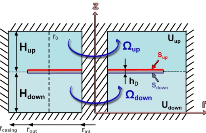
[image:28.612.144.472.480.692.2]The case of study is shown in Figure 2.1.
An annular disk is considered to be submerged and stationary inside a casing. The fluid
field is separated in two fluid fields “up” and “down”. Both fields are considered to rotate as a solid rigid with a constant speed Ωup and Ωdown with respect to the disk. 𝜃,φup and
φdown (not shown in Figure 2.1) are the angular coordinates referred to the disk, the upper
fluid field and the down fluid field. They are positive definite in counterclockwise direction
and therefore the relation between them is:
𝜽= 𝝋𝒖𝒑+𝛀𝐮𝐩𝐭 & 𝜽= 𝝋𝒅𝒐𝒘𝒏+𝛀𝐝𝐨𝐰𝐧𝐭 (2.1)
2.1.1
Vacuum
It is considered that the disk shown in Figure 2.1 with thicknessℎ𝐷 has a density of mass
𝜌𝐷 and it is made of linear, homogeneous and isotropic material. The effects of rotating
inertia, effects of shear deformation are neglected. The transverse displacement of the
annular plate 𝑤 can be described for the annular disk as [48, 49]:
𝝆𝑫𝒉𝑫𝝏 𝟐𝒘 𝝏𝒕𝟐 +𝑫 � 𝝏 𝝏𝒓𝟐+ 𝟏 𝒓 𝝏 𝝏𝒓+ 𝟏 𝒓𝟐 𝝏𝟐 𝝏𝜽𝟐� 𝟐
𝒘=𝟎 (2.2)
In this equation 𝐷 =𝐸ℎ𝐷3�12(1− υ2)is the bending stiffness of the disk, with E and υ the Young and Poisson modulus of the material.
The exact solution for w is given also in the mentioned references:
𝒘=𝒘(𝒓,𝜽,𝒕) =� � 𝑾𝒏𝒎 ∞ 𝒎=𝟎 (𝒓)𝐜𝐨𝐬(𝒏𝜽)𝒆𝒋𝝎𝒏𝒎𝒕 ∞ 𝒏=𝟎 (2.3)
In this solution n is the number of nodal diameters and m the number of nodal circles in the
mode shape. 𝑊𝑛𝑚(𝑟) is a function that involves the use of Bessel functions[48, 49] . Combining Eq. (2.3) and Eq. (2.2) the natural frequencies 𝜔𝑛𝑚can be obtained as:
𝝎𝒏𝒎 = 𝝀𝒏𝒎 𝟐
𝒓𝒐𝒖𝒕𝟐 �
𝑫
In this expression 𝜆𝑛𝑚 depends on the relation of the inner to the outer radius of the disk
and also on the mode shape n, m. A table with different values of 𝜆𝑛𝑚 can be found in both
references [48, 49].
2.1.2
Annular disk in contact with fluid that rotates with respect to
the disk
To obtain the natural frequencies of the plate in contact with fluid, generally the added
virtual mass incremental (AVMI) 𝛽𝑛𝑚 factors [27, 28, 45-47] are calculated. These factors
depend on the characteristics of the disk and also on the boundary conditions of the fluid.
They relate the natural frequencies in vacuum and the natural frequencies in contact with
fluid as Eq. (2.5) shows.
𝝎𝑭𝒏𝒎 = 𝝎𝒏𝒎
�𝟏+𝜷𝒏𝒎
(2.5)
The calculus of the AVMI factors 𝛽𝑛𝑚 implies the calculus of the reference kinetic energy
of the plate and the reference kinetic energy of the fluid [45]. The reference kinetic energy
of an annular plate 𝑇𝑃∗ can be calculated by use of the motion characteristic expressed in
(2.3)[50]:
𝑻∗𝑷 =𝟏𝟐𝝆𝑫𝒉𝑫∫𝒓𝒓𝒎𝒊𝒏𝒎𝒂𝒙∫ 𝑾𝟎𝟐𝝅 𝒏𝒎𝟐(𝒓)𝒄𝒐𝒔𝟐(𝒏𝜽)𝒓𝒅𝒓𝒅𝜽 (2.6)
To calculate the reference kinetic energy of the fluid the velocity potentials
𝑈𝑢𝑝�𝑟,𝜑𝑢𝑝,𝑧,𝑡�,𝑈𝑑𝑜𝑤𝑛(𝑟,𝜑𝑑𝑜𝑤𝑛,𝑧,𝑡) are used [50].
� 𝑼𝒖𝒑�𝒓,𝝋𝒖𝒑,𝒛,𝒕�= ∅𝒖𝒑(𝐫,𝐳)𝐜𝐨𝐬�𝒏𝝋𝒖𝒑�𝒈𝒎𝒏̇ (𝒕) 𝒘𝒊𝒕𝒉𝒈𝒏𝒎(𝒕) =𝒆𝒋𝝎𝒏𝒎𝒕 𝑼𝒅𝒐𝒘𝒏(𝒓,𝝋𝒅𝒐𝒘𝒏,𝒛,𝒕) =∅𝒅𝒐𝒘𝒏(𝐫,𝐳)𝐜𝐨𝐬(𝒏𝝋𝒅𝒐𝒘𝒏)𝒈𝒎𝒏̇ (𝒕) 𝒘𝒊𝒕𝒉𝒈𝒏𝒎(𝒕) =𝒆𝒋𝝎𝒏𝒎𝒕
(2.7)
Where ∅𝑢𝑝,∅𝑑𝑜𝑤𝑛satisfy the Laplace equation (Eq. (2.8)) in the fluid domains defined in Fig. 1. In cylindrical coordinates:
The boundary conditions of the shown case in Figure 2.1 can be separated in the boundary
conditions at the rigid surfaces and the boundary conditions at the disk and interface. At the
rigid surfaces these are:
⎩ ⎪ ⎨ ⎪ ⎧𝝏∅𝒖𝒑 𝝏𝒛 �𝒛=𝑯 𝒅𝒐𝒘𝒏+𝑯𝒖𝒑 = 𝝏∅𝝏𝒓 �𝒖𝒑 𝒓=𝒓𝒄𝒂𝒔𝒊𝒏𝒈 =𝝏∅𝝏𝒓 �𝒖𝒑 𝒓=𝒓𝒊𝒏𝒕 =𝟎 𝝏∅𝒅𝒐𝒘𝒏 𝝏𝒛 �𝒛=𝟎= 𝝏∅𝒅𝒐𝒘𝒏 𝝏𝒓 �𝒓=𝒓𝒄𝒂𝒔𝒊𝒏𝒈 =𝝏∅𝝏𝒓 �𝒅𝒐𝒘𝒏 𝒓=𝒓𝒊𝒏𝒕 =𝟎 (2.9)
The boundary conditions expressed in Eq. (2.9) mean that the fluid in the rigid boundaries
has no velocity perpendicular to the surface. On the disk surface and on at the interface
between two regions, the boundary conditions can be expressed as:
⎩ ⎪ ⎨ ⎪ ⎧ 𝝏∅𝒖𝒑 𝝏𝒛 �𝒛=𝑯 𝒅𝒐𝒘𝒏 = 𝝏∅𝝏𝒛 �𝒅𝒐𝒘𝒏 𝒛=𝑯𝒅𝒐𝒘𝒏 = 𝝏𝒘𝝏𝒕 𝒇𝒐𝒓 𝒓𝒊𝒏𝒕 ≤ 𝒓 ≤ 𝒓𝒐𝒖𝒕 𝝏∅𝒖𝒑 𝝏𝒛 �𝒛=𝑯 𝒅𝒐𝒘𝒏 = 𝝏∅𝝏𝒛 �𝒅𝒐𝒘𝒏 𝒛=𝑯𝒅𝒐𝒘𝒏 𝒂𝒏𝒅 ∅𝒅𝒐𝒘𝒏 =∅𝒖𝒑 𝒇𝒐𝒓𝒓𝒐𝒖𝒕 ≤ 𝒓 ≤ 𝒓𝒄𝒂𝒔𝒊𝒏𝒈 (2.10)
This problem when Ωup=Ωdown= 0 is solved in [31] by use of the Galerkin method. In that case:
𝜽= 𝝋𝒖𝒑 = 𝝋𝒅𝒐𝒘𝒏 (2.11)
In the present case (Figure 2.1), also Eq. (2.1) has to be used to get ∅𝑢𝑝,∅𝑑𝑜𝑤𝑛 since the angular coordinates in Eq. (2.7) and Eq. (2.3) are different. If ∅𝑢𝑝,∅𝑑𝑜𝑤𝑛 are expressed in their respective angular coordinates, the reference kinetic energy of the fluid can be
calculated as [31]:
𝑻∗𝑭 = 𝟏𝟐 𝝆𝑭� � ∅𝑫𝒐𝒘𝒏𝝏∅𝝏𝒛 𝒓𝒅𝒓𝒅𝝋𝑫𝒐𝒘𝒏 𝒅𝒐𝒘𝒏+ � ∅𝑼𝒑𝝏∅𝝏𝒛 𝒓𝒅𝒓𝒅𝝋𝑼𝒑 𝒖𝒑 𝑺𝑼𝒑
𝑺𝑫𝒐𝒘𝒏
� (2.12)
Sup and Sdown are shown in Figure 2.1. The factors AVMI 𝛽𝑛𝑚 for each mode shapes can be
easily calculated as [45]:
𝜷𝒏𝒎 =𝑻𝑭 ∗
2.1.3
Similarity to the rotating disk case
When the disk rotates with respect to the surrounding flow, a rotational velocity component
is induced on the flow apart from the dynamic motion produced by the disk vibration.
Unfortunately, since the flow is assumed to be inviscid, the real flow pattern cannot be
represented with potential flow. The real flow pattern of the disk can be obtained by using
the Navier-Stokes equations analytically [51] or numerically (CFD simulation).
In [8] a rotating disk problem in contact with fluid is studied with a flow where all the
particles of the fluid are moving as a solid rigid with an averaged rotating speed. Under this
assumption, the averaged rotating speed of the real flow pattern with respect to the disk can
be calculated and the problem can be considered as a stationary disk with a flow rotating
with respect to them as shown in Figure 2.1.
2.1.4
Simplified model in the averaged radius
The complexity of the mentioned problem in chap. 2.1 makes the analytical solution of
∅𝑢𝑝,∅𝑑𝑜𝑤𝑛 very complex. For this reason Kubota and Ohashi in [8], tried to simplify this
problem by representing the motion of the disk in an averaged radius. The flow is also
represented by a potential flow in the averaged radius with a constant rotating speed with
respect to the disk. Instead of calculating the reference kinetic energy of the surrounding
fluid, in this case the pressure that the fluid exerts on the disk is considered in Eq. (2.2) to
represent the fluid-structure interaction.
In this study the solution given by Kubota and Ohashi in [8] is extended to two fluid fields
that can rotate at different rotating speeds.
The case of study in Figure 2.1 is characterized now in the averaged radius r0. It is assumed
that the differential coefficients of the fluid and of the disk vibration in the radial direction
are negligible small and that the fluid and disc are vibrating uniformly in radial direction.
For this reason, the upper field and the lower field are two separate fields that are axially
delimited by the disk and by a rigid surface. With this assumptions only the modes with no
diametrical modes (m=0) have been considered. To simplify the nomenclature in this
If the disk motion is represented in the averaged radius 𝑟𝑜= �𝑟𝑖𝑛·𝑟𝑜𝑢𝑡 [8], the Eq. (2.2) for the disk vibrating with the surrounding fluid becomes:
𝝆𝑫𝒉𝑫𝝏 𝟐𝒘 𝝏𝒕𝟐 + 𝑫∗ 𝒓𝒐𝟒 𝝏𝟒𝒘 𝝏𝜽𝟒 =𝒑𝒓𝒐 (2.14)
In this Equation, D* is a parameter that depends on the geometry and material of the disk
and has the same units as the stiffness D. 𝑝𝑟𝑜 is the pressure that the fluid exerts on the disk.
With the simplifications made for the model (uniform vibration in the radial direction), Eq.
(2.3) can be rewritten as:
𝒘= � 𝑨𝒏𝒆𝒋𝒏𝜽𝒆𝒋𝝎𝒏𝒕
±∞
𝒏=±𝟐
(2.15)
The difference between Eq. (2.3) and Eq. (2.15) is also seen in the sign of n. In Eq. (2.3),
which is used commonly to describe the motion of the free vibrations of the disk, only the
positive value of n is considered. However in [8], both positive and negative values are
considered. The sign of n indicates the direction of the travelling wave excited on the disk.
With Eq. (2.14) and Eq. (2.15) natural frequencies of the disk in vacuum can be calculate if
𝑝𝑟𝑜 is set to 0.
𝝎|𝟐𝒏|≥𝟐,𝒗𝒂𝒄𝒖𝒖𝒎 = 𝒏 𝟒𝑫∗
𝝆𝑫𝒉𝑫𝒓𝒐𝟒
(2.16)
These natural frequencies can be also calculated with Eq. (2.4). Comparing both equations,
the value of 𝐷∗ can be obtained.
It is observed that Eq. (2.15) does not consider the modes 𝑛 = ±1 and n=0 which are the lowest modes for a thin disk with 𝑟𝑜𝑢𝑡 ≫ 𝑟𝑖𝑛. The mode n=0 is not considered since the
expression is supposed to be valid for the diametrical mode 𝑛= ±1. Even though, in that study the analytical values for this mode shape show a large error when compared to the
experimental values.
Furthermore in [48, 49], the values for 𝜆𝑛𝑚 using the complete disk equation (Eq. (2.2))
are given. If only the values with 𝜆𝑛0 are considered and the value of 𝐷∗ is calibrated for
𝜆20 ,the following relative errors for the values of 𝜆𝑛0 obtained with the simplified model
(Eq. (2.14)) compared to those ones given in [48] are obtained(Table 2.1):
Table 2.1: Relative error (%) between natural frequencies in vacuum calculated with
the simplified model and the proposed model in [48]
Diametrical mode |𝑛|
rin/rout hD/rout 1 3 4 5 6
0,05 0,04 51,17 1,87 0,28 -1,94 -4,18
0,125 0,02 62,20 -4,53 -6,23 -8,34 -10,43
0,125 0,04 62,32 -4,76 -6,69 -9,08 -11,49
0,125 0,2 58,99 -5,68 -12,87 -21,53 -30,97
0,2 0,04 66,74 -15,56 -18.95 -21,71 -24,41
Table 2.1 shows for which modes and geometries can be used the simplified model to
estimate the natural frequencies of the disk in vacuum. The closest configuration to the
tested disk in the experimental section is marked on Table 2.1. As shown in this table the
mode 𝑛 = ±1 shows a large error for all the geometries of the annular disk, therefore only the modes |𝑛|≥2 will be considered in this simplified model. The mode 𝑛 = ±2 is not shown, since this mode is used to calibrate the parameter 𝐷∗ (and therefore the error is 0).
For thin disks (hD/rout<0,2) with large radius compared to the inner radius (rin/rout<0,15),
the error made with the simplified analytical model is not large for modes higher than
𝑛= ±2.
The analytical expression of a disk having contact with a fluid on its lower surface that
simplifications of the simplified model. Nevertheless, this situation is very difficult to be
tested experimentally (level of fluid will not remain constant [51]) and subsequently no
experimental results are given in [8] . Furthermore this situation is not realistic for the case
of hydraulic turbomachinery, where the rotating parts are totally submerged. The present
deduction is the extension of the simplified model of Kubota and Ohashi [8] for a totally
confined and submerged rotating disk in a tank.
With the assumptions made for the model, Eq. (2.8) can be rewritten for r=r0[8]:
⎩ ⎪ ⎨ ⎪ ⎧ 𝟏 𝐫𝐨𝟐 𝝏𝟐𝑼 𝒖𝒑 𝝏𝝋𝟐 𝒖𝒑+ 𝝏𝟐𝑼 𝒖𝒑 𝝏𝒛𝟐 =𝟎 𝟏 𝐫𝐨𝟐 𝝏𝟐𝑼 𝒅𝒐𝒘𝒏 𝝏𝝋𝟐 𝒅𝒐𝒘𝒏+ 𝝏𝟐𝑼 𝒅𝒐𝒘𝒏 𝝏𝒛𝟐 =𝟎 (2.17)
In this equation U is used instead of ∅ (and Eq. (2.7) is not considered). In this case, the
boundary conditions expressed in Eq. (2.9) for the rigid walls are reduced to:
⎩ ⎪ ⎨ ⎪ ⎧𝝏𝑼𝒖𝒑 𝝏𝒛 �𝒛=𝑯 𝒅𝒐𝒘𝒏+𝑯𝒖𝒑 =𝟎 𝝏𝑼𝒅𝒐𝒘𝒏 𝝏𝒛 �𝒛=𝟎 =𝟎 (2.18)
And the boundary conditions expressed in Eq. (2.10) are reduced to: 𝝏𝑼𝒖𝒑
𝝏𝒛 �𝒛=𝑯
𝒅𝒐𝒘𝒏
= 𝝏𝑼𝝏𝒛 �𝒅𝒐𝒘𝒏
𝒛=𝑯𝒅𝒐𝒘𝒏
= 𝝏𝒘𝝏𝒕 (2.19)
𝑈𝑢𝑝,𝑈𝑑𝑜𝑤𝑛can be obtained separately, using the boundary conditions of Eq. (2.18) and Eq.
(2.19) assuming the vibration of the disk as in Eq. (2.15) and using the relationship between
the stationary and the rotating coordinates of the disk (Eq. (2.1)).Furthermore the
orthogonal condition is considered:
� 𝒆𝒋(𝒏−𝒔)𝝋𝒅𝝋=� 𝟎𝒘𝒉𝒆𝒏𝒔 ≠ 𝒏
𝟐𝝅𝒘𝒉𝒆𝒏𝒔= 𝒏
𝟐𝝅
𝟎
The solution of the velocity potential for the “down” field, with all the mentioned
conditions is given in [8]. Applying this solution, particularized for the case shown in
Figure 2.1: ⎩ ⎪ ⎨ ⎪ ⎧ 𝑼𝒖𝒑� 𝒛=𝑯𝒅𝒐𝒘𝒏= � 𝒋·𝒓𝒐·𝑨𝒏 𝒏 ∞ 𝒏=±𝟏 �𝝎𝒏+𝒏𝛀𝐮𝐩�𝐜𝐨𝐭𝐡 �𝐧𝐇𝐫𝐮𝐩 𝟎 �·𝐞 𝐣𝐧𝛗𝐮𝐩𝐞𝐣�𝝎𝒏+𝒏𝛀𝐮𝐩�𝐭 𝑼𝒅𝒐𝒘𝒏|𝒛=𝑯𝒅𝒐𝒘𝒏= � 𝒋·𝒓𝒐·𝑨𝒏 𝒏 ∞ 𝒏=±𝟏 (𝝎𝒏+𝒏𝛀𝐝𝐨𝐰𝐧)𝐜𝐨𝐭𝐡 �𝐧𝐇𝐫𝐝𝐨𝐰𝐧 𝟎 �·𝐞 𝐣𝐧𝛗𝐝𝐨𝐰𝐧𝐞𝐣(𝝎𝒏+𝒏𝛀𝐝𝐨𝐰𝐧)𝐭 (2.21)
Using the energy Equation in the non stationary form[51], the fluid dynamic pressure
exerting to the disk can be calculated as:
⎩ ⎪ ⎨ ⎪ ⎧ 𝒑𝒖𝒑 = −𝝆𝑭𝝏𝑼𝝏𝒕 �𝒖𝒑 𝒛=(𝑯𝒅𝒐𝒘𝒏) 𝒑𝒅𝒐𝒘𝒏= −𝝆𝑭𝝏𝑼𝝏𝒕 �𝒅𝒐𝒘𝒏 𝒛=(𝑯𝒅𝒐𝒘𝒏) (2.22)
The term 𝑝𝑟𝑜of Eq. (2.14) can be obtained considering the pressure of the upper and lower
fluid:
𝒑𝒓𝒐 = 𝒑𝒖𝒑+𝒑𝒅𝒐𝒘𝒏 (2.23)
Substituting Eq. (2.21) in Eq. (2.22) and adding both pressures together (Eq. (2.23)), the
term 𝑝𝑟𝑜 becomes:
𝒑𝒓𝒐 =𝝆𝑭𝒓𝒐 � 𝑨𝒏 𝒏 ∞ 𝒏=±𝟏 ·�𝐞𝐣𝐧𝛗𝐮𝐩𝐞𝐣�𝝎𝒏+𝒏𝛀𝐮𝐩�𝐭�𝝎𝒏+𝒏𝛀𝐮𝐩�𝟐𝐜𝐨𝐭𝐡 �𝐧𝐇𝐮𝐩 𝐫𝟎 � +𝐞𝐣𝐧𝛗𝐝𝐨𝐰𝐧𝐞𝐣(𝝎𝒏+𝒏𝛀𝐝𝐨𝐰𝐧)𝐭(𝝎𝒏𝒏𝛀𝐝𝐨𝐰𝐧)𝟐𝐜𝐨𝐭𝐡 �𝐧𝐇𝐝𝐨𝐰𝐧 𝐫𝟎 �� (2.24)
� 𝐞𝐣𝐧𝛗𝐮𝐩𝐞𝐣�𝝎𝒏+𝒏𝛀𝐮𝐩�𝐭 =𝐞𝐣𝐧𝛉𝐞𝐣𝝎𝒏𝐭
𝐞𝐣𝝎𝒏𝐭𝐞𝐣𝐧𝛗𝐝𝐨𝐰𝐧𝐞𝐣(𝝎𝒏+𝒏𝛀𝐝𝐨𝐰𝐧)𝐭= 𝐞𝐣𝐧𝛉𝐞𝐣𝝎𝒏𝐭 (2.25)
And therefore: 𝒑𝒓𝒐 =𝝆𝑭𝒓𝒐 � 𝑨𝒏 𝒏 ∞ 𝒏=±𝟏 ·𝐞𝐣𝐧𝛉𝐞𝐣𝝎𝒏𝐭 ·��𝝎𝒏+𝒏𝛀𝐮𝐩�𝟐𝐜𝐨𝐭𝐡 �𝐧𝐇𝐫𝐮𝐩 𝟎 � + (𝝎𝒏+𝒏𝛀𝐝𝐨𝐰𝐧)𝟐𝐜𝐨𝐭𝐡 �𝐧𝐇𝐫𝐝𝐨𝐰𝐧 𝟎 �� (2.26)
The vibration of the disk coupled with the surrounding fluid is obtained substituting Eq.
(2.26) and Eq. (2.15) in Eq. (2.12):
𝝆𝑫𝒉𝑫𝝏 𝟐𝒘 𝝏𝒕𝟐 + 𝑫∗ 𝒓𝒐𝟒 𝝏𝟒𝒘 𝝏𝜽𝟒 − 𝒑𝒓𝒐 =𝟎 → ∑∞𝒏=±𝟐𝑨𝒏𝒆𝒋𝒏𝜽𝒆𝒋𝝎𝒏𝒕(−𝝆𝑫𝒉𝑫𝝎𝒏𝟐+ 𝑫∗ 𝒓𝒐𝟒𝒏 𝟒)− 𝒑𝒓𝒐 =𝟎 (2.27)
The solution of the characteristic Equation (Eq. (2.28)) gives the solution of the natural
frequencies 𝜔𝑛 for each n (positive and negative). This Equation is:
From this Equation, only the positive solution for each nis considered.
2.1.5
Analogy to the modal model
The modal model of 1 DOF consists in a mass, spring and damper. The damper is
considered as a structural damping (general case) that may depend on the frequency itself
[52]. Its motion Equation can be expressed as
𝒎𝒙̈+𝒄𝒙̇+𝒌𝒙= 𝑭(𝒕) (2.29)
Assuming a solution of type 𝑋=𝑥𝑒𝑗𝜔𝑡when 𝐹= 𝑓𝑒𝑗𝜔𝑡, the following transfer function is obtained:
𝟏
−𝒎𝝎𝟐+𝒄𝒋𝝎+𝒌=
𝒙
𝒇 (2.30)
The similarity between Eq. (2.28) and the denominator of Eq. (2.30) permits the following
analogies. 𝒎= �𝐜𝐨𝐭𝐡 �𝒏𝑯𝒖𝒑 𝒓𝒐 �+𝐜𝐨𝐭𝐡 � 𝒏𝑯𝒅𝒐𝒘𝒏 𝒓𝒐 �� 𝝆𝑭𝒓𝒐 𝒏 +𝝆𝑫𝒉𝑫; 𝒄= −𝒋 �𝐜𝐨𝐭𝐡 �𝒏𝑯𝒖𝒑 𝒓𝒐 � 𝟐𝒏𝜴𝒖𝒑+𝐜𝐨𝐭𝐡 � 𝒏𝑯𝒅𝒐𝒘𝒏 𝒓𝒐 � 𝟐𝒏𝜴𝒅𝒐𝒘𝒏� 𝝆𝑭𝒓𝒐 𝒏 𝒌=𝒓𝑫 𝟎𝟒𝒏 𝟒−[𝐜𝐨𝐭𝐡 �𝒏𝑯𝒖𝒑 𝒓𝒐 � 𝒏 𝟐𝜴 𝒖𝒑𝟐+𝐜𝐨𝐭𝐡 �𝒏𝑯𝒓𝒅𝒐𝒘𝒏 𝒐 � 𝒏 𝟐𝜴 𝒅𝒐𝒘𝒏𝟐]𝝆𝑭𝒏𝒓𝒐 (2.31)
Fluid in rest
The effect of a still fluid in the natural frequencies of the disk is to increase the mass of the
disk (added mass effect) and consequently decreases the value of the resonance frequency.
In this case, the same solution for 𝜔𝑛 is obtained for n positive and n negative when
�𝑛𝑝𝑜𝑠�=�𝑛𝑛𝑒𝑔�. Substituting 𝜔𝑛𝑝𝑜𝑠 ,𝑛𝑝𝑜𝑠 and 𝜔𝑛𝑛𝑒𝑔 ,𝑛𝑛𝑒𝑔 in Eq. (2.15), a unique mode
shape with all the points moving in phase or in counterphase (standing wave) is obtained
Effect of fluid rotation
If the fluid rotates, it can be seen (Eq. (2.30)) that an extra stiffness and a complex damping
term appear. The appearance of a complex damping term, causes that 𝜔𝑛𝑝𝑜𝑠 ≠ 𝜔𝑛𝑛𝑒𝑔. Now
substituting 𝜔𝑛𝑝𝑜𝑠 ,𝑛𝑝𝑜𝑠 and 𝜔𝑛𝑛𝑒𝑔 ,𝑛𝑛𝑒𝑔 in Eq. (2.15), a mode shape is obtained for 𝜔𝑛𝑝𝑜𝑠 and a mode shape is obtained for 𝜔𝑛𝑛𝑒𝑔. Both mode shapes are complex mode shapes with
all points moving in a different phase. They can be understood as travelling waves. The
rotation of the travelling waves for 𝜔𝑛𝑝𝑜𝑠 and for 𝜔𝑛𝑛𝑒𝑔is always in countersense.
According to Eq. (2.28), when the rotation speed of the surrounding fluid increases, the
frequency shift between these two peaks also increases.
A physical explanation for this effect is the influence of the added mass of the fluid on a
forward wave and on a backward wave. According to [8], the free vibration of an annular
disk is the superposition of a forward and a backward wave, for each diametrical mode n.
For the annular disk with steady surrounding fluid, the added mass effect of this fluid on
the forward and on the backward wave is the same and therefore both waves will have the
same natural frequency and the corresponding mode shape at this frequency will be the
superposition of both waves, which is a standing wave. With a relative rotation of the
surrounding fluid with respect to the disk, the added mass effect will be different for the
forward than for the backward wave, since the relative velocity of the fluid with respect to
the wave will be different depending on the rotating direction of the wave. This causes, that
the frequency of the backward wave will be different than the frequency of the forward
wave. In this case, for each diametrical mode n a pair of natural frequencies, which
correspond to the forward and to the backward wave, will appear on the disk. A similar
effect is shown in [53], for a fluid-conveying pipe with periodic boundary conditions.
Increasing 𝛺𝑑𝑖𝑠𝑘 will increase 𝛺𝑢𝑝 & 𝛺𝑑𝑜𝑤𝑛 and this will enhance the mentioned effect, which means to increase the difference between both natural frequencies. For higher values
of 𝛺𝑑𝑖𝑠𝑘 than considered in this paper, some terms may be included in Eq. (2.14)[18] (due
to centrifugal and Coriolis forces) and therefore the analytical solution would be modified.
Furthermore, higher velocities of the disk leads to low pressure areas what could generate
and amount of cavitation [56]. Therefore, with the presence of cavitation, the solution of
Eq.(2.14) becomes much more complex.
2.1.6
Validity of the simplified model
The presented simplified model which is an extension of the model proposed in [8] makes
the important simplification of considering the differential coefficients of the motion of the
fluid and disk negligibly small in the radial direction and that the disk and fluid vibrate
uniformly in this direction. Therefore, the vibration characteristic of both fluid and disk can
be represented in an averaged radius r0. In that study experimental results confirm the
analytical model proposed for the case of a standing disk, i.e. Ωup=Ωdown= 0. In this study experimental results will be compared with the simplified analytical model when
Ωup≠Ωdown≠ 0
Due to the simplifications made, this model can only predict the diametrical modes, i.e.
when m=0. As said before, the mode 𝜔0,0 is also not possible for the simplified model,
since the fluid is considered incompressible and the disk vibrates uniformly in the radial
direction. In [8], the simplified model is given for |𝑛|≥ 1 and no geometrical characteristics are imposed on the disk. Table 2.1 shows that the assumptions introduced in
the simplified model do not change substantially the results of the natural frequencies in
vacuum compared to the results where the radial deformation is considered[48, 49], for
modes |𝑛|≥ 2 (specially for modes |𝑛| = 3,4) and for disks with 𝑟𝑜𝑢𝑡 ≫ 𝑟𝑖𝑛.
In fact, since Eq. (2.3) is written as superposition of mode shapes n,m for 0≤ 𝑛,𝑚 ≤ ∞, and w satisfies Eq. (2.2), each mode 𝑛,𝑚 has to satisfy separately Eq. (2.2). For some geometrical conditions of the disk (Table 2.1), some mode shapes satisfy the simplified
form of Eq. (2.2) which is Eq. (2.14). Fortunately, these modes (diametrical modes with
|𝑛| > 2), are commonly the most relevant modes in case of hydraulic runners since they are more prompt to be excited [3, 4], and therefore they will be studied experimentally in this
case.
Finally, due to the assumptions made, no influence of the radial gap can be estimated with