INSTITUTO TECNOLÓGICO Y DE ESTUDIOS SUPERIORES DE MONTERREY
PRESENTE.-Por medio de la presente hago constar que soy autor y titular de la obra
denominada " Hybrid Vehicle With Stirling Engine And Thermal Energy Storage
", en los sucesivo LA OBRA, en virtud de lo
cual autorizo a el Instituto Tecnológico y de Estudios Superiores de Monterrey
(EL INSTITUTO) para que efectúe la divulgación, publicación, comunicación
pública, distribución, distribución pública y reproducción, así como la
digitalización de la misma, con fines académicos o propios al objeto de EL
INSTITUTO, dentro del círculo de la comunidad del Tecnológico de Monterrey.
El Instituto se compromete a respetar en todo momento mi autoría y a
otorgarme el crédito correspondiente en todas las actividades mencionadas
anteriormente de la obra.
De la misma manera, manifiesto que el contenido académico, literario, la
edición y en general cualquier parte de LA OBRA son de mi entera
responsabilidad, por lo que deslindo a EL INSTITUTO por cualquier violación a
los derechos de autor y/o propiedad intelectual y/o cualquier responsabilidad
relacionada con la OBRA que cometa el suscrito frente a terceros.
Hybrid Vehicle with Stirling Engine and Thermal Energy
Storage-Edición Única
Title
Hybrid Vehicle with Stirling Engine and Thermal Energy
Storage-Edición Única
Authors
Erik Wieland Sewe
Affiliation
Tecnológico de Monterrey, Campus Monterrey
Issue Date
2010-05-01
Item type
Tesis
Rights
Open Access
Downloaded
18-Jan-2017 22:05:50
INSTITUTO TECNOLÓGICO Y DE ESTUDIOS
SUPERIORES DE MONTERREY
CAMPUS MONTERREY
DIVISIÓN DE INGENIERÍA Y ARQUITECTURA
PROGRAMA DE GRADUADOS EN INGENIERÍA
HYBRID VEHICLE WITH STIRLING ENGINE AND THERMAL ENERGY
STORAGE
TESIS
PRESENTADA COMO REQUISITO PARCIAL PARA OBTENER EL GRADO
ACADÉMICO DE:
MAESTRO EN CIENCIAS
ESPECIALIDAD SISTEMAS DE MANUFACTURA
POR
ERIK WIELAND SEWE
INSTITUTO TECNOLÓGICO Y DE ESTUDIOS SUPERIORES DE
MONTERREY
CAMPUS MONTERREY
DIVISIÓN DE INGENIERÍA Y
ARQUITECTURA
PROGRAMA DE GRADUADOS EN INGENIERÍA
Los miembros del comité de tesis recomendamos que el presente proyecto de tesis
presentado por el Ing. Erik Wieland Sewe sea aceptado como requisito parcial para
obtener el grado académico de Maestro en Ciencias con especialidad en:
SISTEMAS DE MANUFACTURA
Comité de tesis:
________________________________
Dr. Noel León Rovira
Asesor
_______________________ _________________________
Dr. Ciro Ángel Rodríguez González
Dr. Humberto Aguayo Téllez
Sinodal Sinodal
APROBADO
___________________________
Dr. Ciro Ángel Rodríguez González
Director del Programa de Maestría en Ciencias
con especialidad en Sistemas de Manufactura
Acknowledgements
I would like to thank to …
… Dr. Noel León for making possible this thesis.
… Dr. Ciro Rodríguez, Dr. José Huertas and Dr. Humberto Aguayo for her time and advice. … Claudia Gonzales for her excellent work.
… My family, for their constant support from Germany. … Luis Diego for friendship and feedback.
… Daniel for reviewing the thesis. … All my friends.
Abstract
Advances in electric technology and automotive components make feasible a new kind of hybrid vehicles. The hybrid technology allows gathering advantages from different energy concepts and allows it to eliminate disadvantages which a single energy source or engine concept would present. Hybrid technologies allow using different power sources in one vehicle.
Concentrated thermal solar energy is used as primer energy in a vehicle. Basic components are thermal energy storages and Stirling engines. Heat from the sun is gathered in a place outside the car and stored in a tank. The tank is placed in the vehicle and connected to a Stirling engine. A Stirling engine is a device that converts heat energy into mechanical power. The mechanical power is used in a generator to produce electric energy. The vehicle has an electric system with batteries serving as an energy buffer. Physical bases, components and vehicle concepts are described. A market study provides benchmark of Stirling engines and serial hybrid busses. In a case study several options for a possible prototype are revised. For the Circuito Tec service (a service for students living near the university) a detailed analysis is made. With a GPS the driving profile is recorded. A Matlab model uses this data to calculate energy storages sizes and required engine output. In Autodesk Inventor several CAD models are created in order to represent different space concepts. A vehicle with thermal energy storage based on molten glass is compared to conventional and alternative concepts. MSC Adams/car is used to simulate the vehicle dynamics. The influence of a thermal storage tank with the weight of 996kg is observed. Size, weight and price estimation of different thermal-electric vehicles are compared to conventional vehicles.
Keywords
Table of contents
Table of contents...ii
List of figures...iv
List of tables ...vi
Acronyms ...vii
List of Symbols...vii
Chapter 1. Introduction ...1
1.1 Objective ...1
1.2 Hypothesis ...2
Chapter 2. Theoretical Background ...3
2.1 Stirling Engines ...3
2.1.1 Engine configurations ...3
2.1.2 The Stirling Cycle:...5
2.1.3 Alternatives to Stirling Engines...5
2.2 Hybrid Vehicles ...7
2.2.1 Comparison of different vehicle assemblies...10
2.2.2 Vehicles with Stirling Engines – History ...11
2.3 Patents ...12
2.4 Solar Energy System Design ...13
2.5 Materials...15
2.6 Thermal energy storage tank ...17
2.7 Heat exchanger...17
Chapter 3. Macro vision ...18
3.1 Vehicle to Grid...18
3.2 Competitors and economic rivals...19
3.3 Problems and backup solutions ...20
Chapter 4. Application: Minibus...21
4.1 Market Situation Serial Hybrid Buses ...21
4.2 Components...24
4.2.1 Market situation: Stirling Engines ...24
4.2.2 Cooling system for Stirling engine ...26
4.2.3 Electric Energy Storage...27
4.2.4 Electric engines ...27
4.2.5 Air conditioning ...28
4.2.6 Electric components ...29
4.2.8 Expreso Tec ... 32
4.2.9 Circuito Tec ... 33
Chapter 5. Modeling and simulation... 37
5.1 Load Cases... 37
5.1.1 Drive Cycle ... 37
5.1.2 Vehicle... 37
5.1.3 Vehicle Dynamics... 38
5.2 Model ... 39
5.2.1 Energy calculations ... 40
5.2.2 Configuration ... 41
5.2.3 Simulation Objective ... 42
5.3 Simulations and Results ... 43
5.3.1 Matlab... 43
5.3.2 CAD 3D ... 49
5.3.3 Vehicle Dynamics... 49
5.3.4 FEM analysis... 51
5.3.5 Package dimensions TES ... 55
Chapter 6. Prototype ... 61
6.1 Different concepts for prototypes ... 61
6.2 Basic thoughts ... 61
6.3 Microbus for VIP transport... 62
6.4 Minibus for student transport ... 62
Chapter 7. Conclusions and Recommendations... 64
7.1 Conclusions ... 64
7.2 Recommendations... 66
7.3 Future Work ... 66
References... 67
Appendix I – Matlab Program Code ... 69
Appendix II - Student Transport ITESM ... 78
Appendix III - Virtual Test Track ... 79
List of figures
Figure 2.1 Different configurations of Stirling engines [2] ...4
Figure 2.2 Free piston Stirling engine [4] and ...4
Figure 2.3 Stirling Cycle [3], step 1,2,3 and 4 ...5
Figure 2.4 Rupp Hot Air Engine [7] ...6
Figure 2.5 Closed Brayton Cycle Engine ...6
Figure 2.6 Cutaway View of a Capstone Microturbine Generator [9]...7
Figure 2.7 Hybrid propulsion concepts – parallel configuration ...8
Figure 2.8 Hybrid propulsion concepts – serial configuration ...8
Figure 2.9 Hybrid propulsion concepts mixed configuration ...8
Figure 2.10 Power electric motor / Stirling engine ...9
Figure 2.11 Efficiency of different vehicle concepts [11] ...10
Figure 2.12 Hybrid vehicle with Stirling engine; Solar power tower efficiency [1]...10
Figure 2.13 GM Stir-Lec I 1969, (http://www.bangshift.com) ...11
Figure 2.14 Hybrid Vehicle with Stirling Engine and Thermal Energy Storage...12
Figure 2.15 US 7,469,760 B2, US 2008/0121755 A1 ...13
Figure 2.16 Solar Radiation in kWh/ (m², year) [11]...13
Figure 2.17 Concentration Rate vs. Absorber Temperature [1] ...14
Figure 2.18 Reflecting Schemes for Concentrating Solar Energy [20] ...14
Figure 2.19 Fresnel lens [21]...15
Figure 2.20 Virtual Prototype of Solar Energy Storage Tank [25]...17
Figure 3.1 Absorption cooling [http://www.dometic-waeco.com/] ...18
Figure 3.2 Vehicle 2 Grid [26]...19
Figure 3.3 Solar Carport (www.dachscheich.com)...19
Figure 4.1 Azure Citibus [31]...21
Figure 4.2 Daimler Buses NA - Orion VII Hybrid...22
Figure 4.3 EBUS [32] ...22
Figure 4.4 Transit Bus Configuration; DesignLine Bus [9] ...22
Figure 4.5 Solaris Urbino 18 Hybrid [33] ...23
Figure 4.6 Toyota Coaster Hybrid EV[34] ...23
Figure 4.7 MB Citaro G Blue Tec Hybrid city bus [30] ...24
Figure 4.8 Comparison of Battery Characteristics [38] ...27
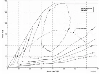
Figure 4.9 Motoring efficiency map Power Phase 145...28
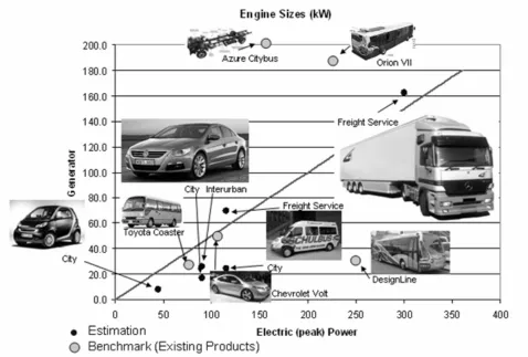
Figure 4.10 Engine Sizes: ICE vs. Stirling Engine ...30
Figure 4.11 Routes Expreso Tec...32
Figure 4.12 Chassis MB 1219 [40] and Ayco Magno 1040 SC bodywork ...32
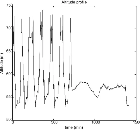
Figure 4.14 Altitude profile Expreso Tec Cumbres... 33
Figure 4.15 Mercedes Sprinter 515 CDI, Toyota Hiace... 34
Figure 4.16 Routes Circuito Tec vs. real data October 2009 ... 34
Figure 4.17 Use of Circuito Tec Service ... 35
Figure 4.18 Velocity Profile Circuito Tec... 36
Figure 4.19 Altitude profile Circuito Tec... 36
Figure 5.1 Distance between two waypoints ... 37
Figure 5.2 Vehizero serial hybrid truck [43] ... 38
Figure 5.3 Test Road ADAMS/car ... 39
Figure 5.4 Cleanergy V161 Stirling Engine [44]... 41
Figure 5.5 Matlab Macro ... 43
Figure 5.6 Flowchart Matlab Simulation ... 44
Figure 5.7 Energy Consumption at Constant Speed ... 45
Figure 5.8 Result Matlab Simulation: SOC ... 46
Figure 5.9 Actual Power at Wheel ... 46
Figure 5.10 Actual Power for Selected Data Sets ... 47
Figure 5.11 EES: 15kWh, 10kWh, 5kWh... 48
Figure 5.12 5kW Stirling engine and 10kWh EES ... 49
Figure 5.13 Basic 3D Model... 49
Figure 5.14 ADAMS/car simulation... 51
Figure 5.15 FEM simulation results ... 52
Figure 5.16 Location of Stress Measurements ... 53
Figure 5.17 Stress vs. time ... 53
Figure 5.18 2600kg vs. 3721kg, point 1 and 2, von Mises stress... 54
Figure 5.19 2600kg vs. 3721kg, point 4, von Mises stress... 54
Figure 5.20 Cylindrical TES vs. rectangular TES ... 55
Figure 5.21 Package Concept, rectangular TES ... 56
Figure 5.22 Package Concept, rectangular TES: Step 1,2 and 3... 56
Figure 5.23 Package Concept, rectangular TES: Step 4... 56
Figure 5.24 Package Concept, rectangular TES: Step 5... 57
Figure 5.25 Alternative Chassis... 57
Figure 5.26 TES 3000°C... 58
Figure 5.27 Electric Vehicle for Circuito Tec – Deep Cycle (left) vs. Li-Ion (right) ... 58
Figure 5.28 Conventional Serial Hybrid Configuration ... 59
Figure 5.29 Comparison Vehicle Concepts ... 60
List of tables
Table 1.1 Potential of renewable energy [1]...1
Table 2.1 Energy Storage ...16
Table 4.1 Benchmark Stirling Engines ...25
Table 4.2 Stirling Engines: Commercial Applications...26
Table 4.3 Vehicles – main characteristics...31
Table 4.4 Vehicle Concepts - Energy Storage ...31
Table 4.5 Statistics Circuito Tec...35
Table 5.1 GPS Sample Data ...37
Table 5.2 Formulas for Energy Calculations [10] ...40
Table 5.3 Vehicle parameters Vehizero ECCO-C...41
Table 5.4 Vehicle weight ...42
Table 5.5 Result Matlab Simulation: Energy Consumption...45
Table 6.1 Scaling prototypes...62
Table 7.1 Actual Vehicle Costs Circuito Tec ...64
Table 7.2 V2G economics ...65
Acronyms
AC Alternating Current ATV All Terrain Vehicle CAD Computer Aided Design CAE Computer Aided Engineering
DC Direct Current
DOE Department of Energy (USA) ECE External Combustion Engine EES Electric Energy Storage ESS Energy Storage System FEM Finite element method
GM General Motors
ICE Internal Combustion Engine
ITESM Instituto Tecnológico y de Estudios Superiores de Monterrey PCM Phase Change Material
SBI Stirling Biopower Inc. (former: STM) STM Stirling Thermal Motors Inc. (today: SBI) TES Thermal Energy Storage
TRIZ The theory of inventor's problem solving V2G Vehicle to Grid
List of Symbols
Af Frontal area cd Air drag coefficient cr Tire rolling coefficient E Energy
Ea Energy used for acceleration Eec Electric energy consumption Eair Energy used by air drag Epot Potential energy
Er Energy used by rolling resistance Etotal Total energy consumed
F Force
Fa Force against vehicle acceleration
Fair Force against vehicle motion caused by air drag Fpot Force against vehicle motion caused by hill climbing Fr Force against vehicle motion caused by rolling resistance g Gravitational acceleration
h Height
i Overall gear ratio
Iw Moment of inertia of the wheels Ieng Moment of inertia of the engine m Vehicle mass (empty)
mmax Maximum vehicle mass P Power
Pa Power required to accelerate
Pconst Power required to move a vehicle at constant speed rstat Static radius of the tires
rdyn Dynamic radius of the tires s Distance
Chapter 1. Introduction
The present and future situation in energy availability and the increasing environment contamination require drastic changes in the human life if we want to keep our current lifestyle. The crude oil reserves are being diminished and at the same time, the demand for transport is growing day by day, especially in emergent countries traffic is augmenting fast. In first world countries people tend to live at longer distances from their work increasing daily commute between house and work. Nowadays the transportation system is mainly based on gasoline and diesel powered ICE, with all their serious disadvantages: polluting escapes, noise and dependency on oil. This situation justifies putting our best effort in the development of technologies and systems that promise an exit from oil dependency and that promise less contamination. Many alternatives were developed and presented in the past to eliminate the ICE, but still none of them had great success. Advances in electric technology and automotive components make feasible a new kind of hybrid vehicles, using different power sources. The hybrid technology allows gathering advantages from different energy concepts and is able to eliminate disadvantages which a single energy source would present. In actual vehicles as for example the Toyota Hybrid or diesel-electric locomotives this effects can be observed, examples are greater efficiency and brake energy recuperation. Still, the actual technology leaves place for improvements and further investigation, as for example the implementation of renewable energy sources. Depending on location and kind of vehicle, there are different forms of renewable energy.
Theoretical Potential (1018J/year)
Technical Potential (1018J/year)
Solar 2,500,000 600
Wind 100,000 100
Biomass and
Geothermic 4,000 380
Hydraulic 287 134
Total 2,604,287 1,088
Table 1.1 Potential of renewable energy [1]
Table 1.1 shows the potential of different types of renewable energy, in particular the solar energy has to be mentioned, if we could gather the solar energy of one hour, than we would be able to satisfy the actual global energy consumption of more than one year (340*1018J/year) [1]. It is important to state that there is a great amount of different renewable energy sources. For every location and application the most convenient energy source should be searched. In the case of the city of Monterrey, Mexico, the solar energy offers great opportunities. But one of the challenges is to make the solar energy accessible for the use in vehicles. One possible solution are tanks that store concentrated solar thermal energy.
In many investigations for new energy concepts based on renewable energies, presented prototypes are small lightweight cars, with the intention to use small fuel effective engines. In this investigation, the aim is to create a vehicle concept that can be used within the community of the ITESM. Student transportation is a good opportunity to introduce and promote technology.
On those bases, the present master thesis presents and further develops a concept for a hybrid vehicle, which uses solar energy as its basic energy source. This investigation is divided in seven chapters; the second consists in the theoretical background in which physical bases, components and vehicle concepts are described. Then, in the third chapter, other aspects of the new proposed technology are mentioned, such as competitors and economic basics. In the fourth chapter, the design process of a vehicle for student transportation is shown, including actual market situation and components. The fifth chapter deals with the evaluation of the minibus in computer simulations, the sixth describes the planning of a prototype. Finally, in the last chapter recommendations and conclusions are exposed.
1.1 Objective
Another section is dedicated to Stirling engines including a benchmark of actual market situation. Finally, different vehicle concepts will be presented and evaluated and joint with the results of the investigation in Stirling engine and thermal energy storage. These concepts indicate possible areas of hybrid thermal vehicles, their benefits but also their restrictions.
The Intention of the present work is to find a concept that can be implemented within the ITESM, campus Monterrey. For that reason, local student transportation is observed; properties of actual vehicles are revised. After choosing a case study, the first step is to determine the energy use, sizes for energy storage and engines. Next objective is to find out how does a TES affect to the vehicle dynamics and the changes in comparison to a reference vehicle. Another topic is the rough cost estimation that provides the information about what should be the maximum price for the new concept to be competitive.
The objective is to work out the new concept, describing its general properties, benefits and restrictions, without going into too much detail. The detailed vehicle assembly and component connections for example are not included on the scope of the present work and would be part of following investigations.
1.2 Hypothesis
Chapter 2. Theoretical Background
This chapter presents the background in which this investigation takes place, most important components and theory are described. Focus is on solar energy, Stirling engines and hybrid vehicle concepts.
2.1 Stirling Engines
A Stirling engine is a device that converts heat energy into mechanical power. An external heat source provides thermal energy which is used to heat one side of the engine. The other side is kept cold and the temperature difference is used to drive the engine, the cycle is described in 2.1.2 . The engine is designed so that the working gas is generally compressed in the colder portion of the engine and expanded in the hotter portion resulting in a net conversion of heat into work. An internal regenerative heat exchanger increases the Stirling engine's thermal efficiency. Compared to simpler hot air engines lacking this feature, the colder portion are not connected directly to the hotter portion, the working fluid first has to pass the regenerator, pre-heating respectively pre-cooling the gas.
Benefits of Stirling engines
• They have a wide application area and can be driven by every possible heat source, by solar or geothermal energy, by fuel combustion, as for example biogas, or by re-using waste heat.
• They assembly basic, they have no valves.
• They emit less noise than an ICE.
• They can be built air-independent, as for example in the use of submarines
• Startup is possible at low temperatures, they don’t present problems with frozen oil. Disadvantages
• Size: actual Stirling engines need more space than actual ICE providing the same power output.
• Costs: due to the small production and especial materials which can resist high temperatures, actual Stirling engines are expensive.
• Large temperature differentials are required.
• Start-up time: the engine needs to warm up before it can be used.
• Change of velocity and power output: the engines output cannot be changed immediately, similar to the start-up it needs to warm up or cool down
• Sealings are problematic, especially at the hot side, due to high temperatures and high working gas pressures.
Today’s commercial applications are solar power generation, combined heat and power plants and cyrocoolers, that means that the process is inverted and the Stirling engine is driven for cooling. There are plenty of model engines for toys and academic proposes, but it is more difficult to obtain more powerful engines, paragraph 4.2.1 provides a closer look to the actual market situation of Stirling engines > 500We.
2.1.1 Engine configurations
There are many possible configurations for Stirling engines, the most common are: Alpha, Beta, Gamma, and free piston Stirling.
• Alpha Stirling:
An alpha Stirling contains two power pistons in separate cylinders, hot and cold. The hot cylinder is heated by any heat source and the cold cylinder cooled by another medium to create a temperature differential. Both cylinders are connected by a tube system, and may have a regenerator installed. This engine is simple, both cylinders can be connected by one crankshaft but the sealing of the hot cylinder is critic and solutions cause side effects like additional dead space. Another downside is the sealing of two cylinders instead of one single sealing in other configurations.
• Beta Stirling
configuration. It does not extract any power. A great advantage is the lack of hot moving seals. A negative point is the complicated drive system, for example a rhombic drive, needed to couple the movement of the piston and the displacer.
Figure 2.1 Different configurations of Stirling engines [2]
• Gamma Stirling
A gamma Stirling is a beta Stirling, but has the power piston mounted in a separate cylinder than the displacer piston. The gas can flow freely between the two cylinders. This configuration produces a lower compression ratio but is mechanically simpler and often used in multi-cylinder Stirling engines [3].
• Free Piston
In the free piston configuration, the Stirling engine has no crankshaft but a spring or similar mechanical device, heated on one end and cooled on the other, the expansion and cooling of the gas drives the piston back and forth in the cylinder. The work performed by this piston-motion can be converted into electric energy by a linear alternator. See Figure 2.2. Benefits of this configuration is the simple assembly, it has few moving parts and no rotational movement. One of the critical point is the friction between piston and cylinder.
[image:17.612.49.493.100.332.2]• Other configurations
Figure 2.2 Free piston Stirling engine [4] and Alternative Stirling Engine Configurations [5],[2]
2.1.2 The Stirling Cycle:
All Stirling Engines have two sections, one of high temperatures and the other of low temperatures. The operating principle is to augment the pressure of the working gas in the hot side of the engine. This is reached by applying heat and resulting gas expansion. On the cold side, heat is dissipated and the working gas contracts. At continuation, the Stirling cycle will be on an alpha Stirling:
Figure 2.3 Stirling Cycle [3], step 1,2,3 and 4 The upper red part shows the hot side of the engine, the blue one is the cold side.
• Step 1
In the first step the gas in the hot side has been heated and the force created by gas expansion has moved the piston to the left side. The crankshaft will continue its motion, and starts to push the hot gas towards the cold side.
• Step 2
The gas has reached its maximum volume and heat is extracted on the cold side. The piston continues pushing the gas towards the cold side. The working gas starts to contract.
• Step 3
Most of the working gas is in the cold side where heat is extracted. The piston is pulled downwards by gas contraction.
• Step 4
The working gas has reached the minimum of its volume and restarts the cycle by expanding on the hot side, pushing the piston to the left.
The idealized Stirling cycle equals to the hypothetical Carnot cycle, without losses it could reach the highest efficiency attainable by any heat engine. Because of friction, thermal losses and irregularities the idealized process cannot be realized. In most cases, a number of deviations must be accepted which reduce both efficiency and power density [2]:
• The piston movement cannot be designed to perform the idealized movement.
• The regenerator does not reach 100% efficiency.
• Surface designed for better heat transfer does not meet perfectly the requirements of the idealized cycle.
• The working fluid has friction in tubes, cylinders etc.
• Mechanical friction.
• Dead space inside the engine (heat exchangers, regenerator etc.) reduces the compression ratio.
• Piston seal leakage and pressure drop across the heat exchangers and regenerator reduce efficiency.
In total, these deviations lead to a process significantly different from the ideal process; modern engines achieve approximately 30% efficiency (see Table 4.1).
2.1.3 Alternatives to Stirling Engines
• Silicon Nanowire
Silicon has the ability to convert heat into electricity by thermoelectric conversion, without any mechanical component. [6] presents investigation in new technologies to increase this ability by as much as 100 times. This is reached by fashioning the material into nanowires with diameters of 10 to 100 nanometers and introducing defects in silicon that slowed the flow of phonons — the acoustic vibrations in the crystal lattice of a material that carry heat. Otherwise the thermal conductivity of silicon would be too high and it would be difficult to create the necessary temperature differential.
• Hot Air Engine – Rupp
This engine is simpler than a Stirling engine, it has less components, as a difference thisis an open cycle, described in [7]. This engine can run in every position and in both directions, it needs pre-heating and an impulse to start working.
Figure 2.4 Rupp Hot Air Engine [7]
• New Stirling / Brayton Engine
This concept searches the advantages of Stirling and Brayton engines. A Brayton engine is basically composed of a compressor, a combustor and a turbine. Well-known applications of the Brayton technology are turbines in jet planes. It consists of an open cycle, the gas used in the engine, typically air, is renewed at the beginning of every new cycle, in [8] the function is described:
“Initially the gas enters to the compressor where its volume is reduced adiabatically. Later the gas is mixed with some kind of combustible inside the combustor where it ignites producing a change of temperature a constant volume increasing its pressure. The gas passes then through the turbine where the pressure is converted into mechanical energy. Then, the gas is expulsed to the atmosphere where it reduces its temperature until it reaches normal conditions. After that, the cycle begins again.”
As the Stirling engine, an engine based on the Brayton cycle, can be driven by many heat sources, such as waste heat, solar thermal energy, amongst others. [8] describes the invention process using TRIZ for a new design that combines the advantages of both cycles: The Brayton engine is changed into a closed cycle, the proposed cycle follows the same phase diagram pattern that the Brayton cycle does, but the heat is applied externally just the same way as it is applied to a Stirling engine.
Figure 2.5 Closed Brayton Cycle Engine
Another research aim was to develop an affordable engine concept, for this to happen, engine parts are selected from commercial providers, with preference to components from mass production, for example compressors and turbines used in the automotive industry. This concept is subject of the Mexican patent application number MX/a/2008/012924 “Ciclo mixto de Stirling y Brayton para convertir energía térmica a energía en forma de movimiento rotatorio”.
• Microturbine Generator
Capstone Turbine Corporation describes the functionality of a microturbine (a small gas turbine) as follows [9]: “Microturbines use a continuous shaft rotation to pull in air, compress it, add fuel for combustion, and use the resulting heated air to drive a turbine wheel. The turbine wheel provides the power to drive the compressor wheel as well as a generator mounted on the same rotating assembly. A recuperator (or air-to-air heat exchanger) is provided to extract energy from the exhaust stream and recycle it to preheat the incoming air to the combustion chamber”.
Figure 2.6 Cutaway View of a Capstone Microturbine Generator [9] Actually, there is a research project with the aim to drive microturbines by solar energy.
2.2 Hybrid Vehicles
By their structure, hybrid vehicles can combine the advantages of different energy and engine concepts. With an intelligent structure, it is possible to change drastically the vehicle’s properties; they may exhibit the following advantages [10]:
• Reduces fuel consumption
• Lowest possible emissions
• Noise reduction
• Increased operational comfort
• Locally emission-free and noise-free operation in sensitive areas
Nowadays, the majority of the hybrid cars build in series production are vehicles with ICE and electric engine. The market leader and the best example is the Toyota Prius. Nevertheless, there are many other concepts to combine different engines and energy storages, shortly many new hybrid vehicles will enter the market. Disadvantages are the complicated structure as well as the higher weight and the rising costs. There are three fundamental concepts for the structure of the drive train and the connection of the different engines: parallel hybrids, serial hybrids and mixed hybrids [10]:
• Parallel hybrids:
Figure 2.7 Hybrid propulsion concepts – parallel configuration
The car can be driven electrically at low speed, for example in city use. Interurban and at higher velocities and larger distances, the car uses the ICE In moments where extra power is needed, for example when climbing hills or when passing other vehicles, both engines combine their power to provide better acceleration and higher speed. Additional improvement potential may be obtained with regenerative braking and shutdown of the ICE: waiting on red lights, and traffic jams.
• Serial hybrids:
Figure 2.8 Hybrid propulsion concepts – serial configuration
In serial hybrids, the wheels are driven entirely by electric motors, with electrical energy supplied by an electric generator. The battery, as an energy buffer, permits complete decoupling of the engine/generator combination from the drive. In this way, the electricity generation may be set independently from the momentarily driving demands and can be optimized for maximum efficiency or lowest contamination possible. Brake energy can be re-used. All energy saving, however, is diminished because all the output of the first engine must pass through the entire electrical efficiency chain. In this combination, the engine/generator-combination must be powerful enough to satisfy at least the vehicles average energy consumption. The electric motors must meet all the requirements for maximum acceleration and hill climbing with a fully loaded car. This implicates that the electric components installed in serial hybrid vehicles resist larger loads than the ones installed in parallel hybrids. Another approach for serial hybrids is the use of range extenders in electric cars, a small ICE combined with a generator is used to extend the battery range.
• Mixed hybrids:
Figure 2.9 Hybrid propulsion concepts mixed configuration
The most famous example for this concept is the Toyota Prius.The advantage of mixed hybrids is the possibility to combine properties of serial and parallel hybrids, but at the same time increases the system complexity and, more important, the advanced, cost-intensive control.
In the present master thesis, the use of Stirling engines and thermal energy storage in hybrid vehicles is proposed. For this application, the most adequate concept is the serial hybrid where the Stirling engine has no direct connection to the driven wheels, so the Stirling engine can work at its best operating point, and the batteries serve as a buffer. Stirling engines downsides as long warming up phase and the retarded change of revolution speed are eliminated. Other benefits are that products designed for hybrid or electric vehicles can be used. The more complicated mixed hybrid configuration is not favorable in this application, in only few situations the Stirling engine could directly drive the wheels.
The emphasis of this work is the energy concept and its application in vehicles. The focus is energy supply, storage and transformation, as well as vehicle concepts for different types of use.
Figure 2.10 Power electric motor / Stirling engine
Figure 2.10 shows the interaction between electric motor and Stirling engine. The electric motor provides a maximal (short time) power output for vehicle propulsion of Pmax, and supports an average (long time) power
output of Pd. The actual vehicle power consumption is described by Pactual, the average value of Pactual must
be smaller/equal to the power provided by the Stirling engine PSt. In Figure 2.10 Pactual indicates different
driving conditions:
• Brake energy recovery: Pactual < 0, generated energy is transferred to the batteries
• Acceleration when overhauling or hill climbing: Pd < Pactual < Pmax, additional energy is provided by the
batteries
• Moderate driving: 0 < Pactual < Pd, excess energy is stored in the batteries
2.2.1 Comparison of different vehicle assemblies
Figure 2.11 Efficiency of different vehicle concepts [11]
Figure 2.11 A and B show the efficiency of conventional vehicles with single ICE and mechanical transmission reached in their best operation point. Most of the energy is lost in heat, about 60%, and the remaining energy for propulsion is about 30%. Diesel engines have better efficiency than gasoline engines (36% to 28%) [12]. In normal drive cycles the efficiency is about 15% to 20% due to idle running engines when traffic stops, braking energy losses and not-optimal operating point of the ICE. Fuel cell powered vehicles (D) lose most part of their energy for supply and use of H2 (60%) [12]. Finally remain 17% for net propulsion in optimal drive cycles and about 13% in typical cycles. Vehicles with energy storage in Li-Ion-batteries (C) offer a significant better efficiency, there is no need to transform energy, and therefore 72%/55% for ideal/typical cycles can be reached.
Figure 2.12 (left) shows the complete energy chain for a hybrid vehicle with thermal energy storage and Stirling engine, beginning with solar thermal energy and finishing with net propulsion. Thermal energy is stored in a PCM and transferred by a heat exchanger to a Stirling engine. The Stirling cycle converts about 30% of this energy into electrical power used by an electric system for propulsion. Possible improvements are heat and brake energy recovery. As a reference, in Figure 2.12 (right), the energy chain for a solar power tower is presented. About 19% of the solar energy is converted into electric energy [1].
2.2.2 Vehicles with Stirling Engines – History
Years ago several companies worked on alternative vehicle concepts, especially Ford and General Motors presented outstanding concepts. Amongst others, investigations were made to implement a small nuclear reactor in personal vehicles. Nevertheless, none of them passed to series production, many concepts didn’t even reach the prototype status.
For the present investigation, the first reference found is from 1969, a General Motor prototype, based on an Opel Kadett body, where a Stirling engine and a electric storage and drive system were built in. Popular Science [13] had the possibility to test drive the car and provides in its report interesting information: The vehicle was planned to reach low emissions, by using a Stirling engine and an electric drive system. Main components were 14 automotive type 12 volt batteries and controls stored under the hood and a Stirling engine in the back. The Stirling engine works at 2800 r.p.m., running quiet. The three-phase induction motor is able to accelerate the vehicle in 10 to 20 seconds to 30m.p.h which is about twice the time of a normal car of that year. Total weight is about 3100 pound, including two passengers. Maximum average speed was 30 m.p.h., maximum speed 55 m.p.h. The maximum distance depended on the size of the gasoline tank. In the driven version the vehicle was able to drive about 150 to 200 miles on gasoline and 15 to 30 miles with only electric power. Start-up time of the car was limited by the Stirling engine and took about 20 seconds.
Figure 2.13 GM Stir-Lec I 1969, (http://www.bangshift.com)
In 1971, the Department of Energy (DOE, United States of America) started a research program about the use of Stirling engines in vehicles. Together with other institutions and enterprises, like the NASA, General Motor (GM) and Stirling Thermal Motors Inc. (STM), to mention the most important ones, they achieved to build several prototypes with fuel tanks, Stirling engines and direct power transmission between the engine and the wheels. Technical reports [14], [15], [16], show that these cars had properties similar to conventional cars of that epoch. Still, the Stirling engines were problematic.
(former: STM) continues in the development of Stirling engines opening up new business in Stirling engine power generators.
Another important source is [18], a detailed design report for a TES system and its implementation in a compact sized automobile. Materials for storing thermal energy are LiF and NaF/MgF2. Propulsion motor is a
Stirling engine, the thermal-electric serial hybrid approach is not described. Total tank weight is about 500kg for approx. 100kWth.
2.3 Patents
• History
The patent US 5,634,339 describes a turbine adapted to thermal energy storage. Turbine and tank are connected by a working fluid. The thermal storage is recharged by a hot fluid, gasoline or electric energy. The US patent 5,172,784 mentions a hybrid vehicle with external combustion engine, based on liquid combustibles. W. Fopper describes in the documents DE 19,734,733 and US 6,272,856 [19] a method for storing thermal energy and its use in vehicles. Electric energy is used for heat generation. The pending Mexican patent Mx/a/2008/015984 describes a mobile heat-storing device, using molten salt for energy storage.
• Patent application MX/A/2009/ 000965
[image:25.612.102.441.366.584.2]The pending Patent MX/a/2009/00965 named “Sistema Recolectar De Energía Aplicable A Autos Hibridos” describes a system to gather solar energy and the use of this energy in hybrid vehicles. The vehicle’s main component is a thermal energy storage system. The TES is previously filled in fixed places and afterwards installed in the vehicle. A heat exchanger connects the thermal tank with a Stirling engine. An electric propulsion system moves the car. The Stirling engine can be exchanged by any element able to convert heat energy into mechanical energy, as for example a closed Brayton cycle turbine.
Figure 2.14 Hybrid Vehicle with Stirling Engine and Thermal Energy Storage
The temperature gradient between storage material and ambient air temperature is reduced. Air from the outside of the car (13) is used to cool down the cold side of the Stirling engine (8), the warmed-up air (14) is guided into one layer of the tank (4) and finally leaves the car (15).
• Other Patents
US 7,469,760 B2 “Hybrid electric vehicles using a Stirling engine”: Dean Kamen claims a personal vehicle for transporting a user over a surface. Components are an external combustion engine, generator for converting the mechanical energy to electrical energy, electric storage system and drive motor in serial hybrid configuration. To generate heat liquid fuel or natural gas is burned.
Figure 2.15 US 7,469,760 B2, US 2008/0121755 A1
US 2008/0121755 A1 “Rankine-Brayton Engine Powered Solar Thermal Aircraft”: This document describes a solar thermal powered aircraft with a Rankine-Brayton hybrid cycle heat engine. It has a thermal battery, preferably containing a lithium-hydride, which is connected by a working fluid to the engine. A solar concentrator, such as a reflective parabolic trough, is movably connected to an optically transparent section of the aircraft body for receiving solar energy. The concentrated solar energy is collected by a heat collection and transport conduit, and heat transported to the thermal battery. US 2009/0313994 A1 “Self-pressurizing Stirling Engine”: Describes an improved Stirling Engine for the patent prior mentioned.
2.4 Solar Energy System Design
Solar energy is the most powerful renewable energy source [1].
Figure 2.16 Solar Radiation in kWh/ (m², year) [11]
Solar radiation can be expressed by energy per surface and year. In Western Europe (Germany) each year in 1m² about 1000kWh can be collected. In other regions, close to the equator, it can be up to 2500kWh/ m² [1]. For higher energy reception tracking mechanisms can direct surfaces towards the sun. Especial in southern and northern regions this has great effect to the efficiency. In Southern Spain actual photovoltaic panels with 2-axis tracking can gather an annual yield of about 340kWhe/ m² and in the northern Sahara this value
increases to more than 400kWhe/ m² [1].
• Gathering Solar Energy
convection and thermal conduction. Increase of the radiating power on the absorber by focusing and concentrating the incident solar radiation.
• Solar Thermal Systems
Solar radiation can be concentrated by mirrors or lens to attain higher temperatures [1], see Figure 2.17.
5489
3657
1937
970
120 426
0 1000 2000 3000 4000 5000 6000
1 10 100 1000 10000 100000
concentration ratio
ab
so
rb
er
tem
p
er
at
u
re °
C
Figure 2.17 Concentration Rate vs. Absorber Temperature [1]
For solar thermal systems solar radiation is converted into thermal energy at the desired temperature. It may be stored in a thermal energy storage material and then converted into electricity.
Figure 2.18 Reflecting Schemes for Concentrating Solar Energy [20]
• Parabolic trough
Parabolic trough concentrates incoming solar radiation onto a line running the length of the trough. A tube (receiver) carrying heat transfer fluid is placed along this line, absorbing concentrated solar radiation and heating the fluid inside. The trough must be tracked in one axis. Because the surface area of the receiver tube is small compared to the trough capturing area (aperture), temperatures up to 400oC can be reached without major heat losses [20].
• Parabolic dish
A parabolic dish concentrates the incoming solar radiation to a point where a Stirling engine can be mounted or a material can be heated. Parabolic dishes must be tracked in the two axes to follow the sun during the day [20].
• Central receiver system
• Fresnel Lens
Plane Fresnel lenses can act as spherical lenses. By their flat design, they offer space and weight saving, short focal lengths and lower prices. They are widely used for camera field lenses or rear projection screens.
Figure 2.19 Fresnel lens [21]
In Mexican patent application MX/a/2008/016474, “Lente concentradora de energía solar por refracción con alta eficiencia”, a Passive Tracking Enhanced Solar Concentrator Device Performed by Fresnel lens is described. The main idea of this design is to create a simple structure able to track the suns trajectory without any movement of the lens. This guides to an effective and low priced system for concentrating solar thermal energy.
In practice, computed ideal values for concentration and temperature (see Figure 2.17) cannot be reached because of different natural dissipation factors. The substantial dissipation factors imply [1]: Mirror errors (incomplete reflection or surface defects); absorber losses (reflection, radiation, and convection); orientation errors (tracking, absorber adjustment, and oscillation due to wind load).
• Photovoltaic Systems
For photovoltaic systems, intercepted solar energy is converted directly into low voltage direct current electricity [20]. They are based on the photoelectric effect which was discovered first in 1893 by Alexander Bequerel. In a solar cell, the production of the energy takes place completely without moving parts and completely without noise. The solar cell does not suffer changes during the energy production process.
2.5 Materials
Thermal energy storage materials can be classified into three different types:
• Sensible Heat Storage
Thermal energy can be stored in a material as sensible heat by raising its temperature.
• Latent Heat Storage
Thermal energy can be stored in a material by using the energy absorbed or released during the isothermal phase change.
• Chemical Reaction Energy Storage
Thermal energy can be stored by using the endothermic reaction of the chemicals between different materials. When the process is inversed, the heat is released.
In [19], materials are described for thermal energy storage up to 850°C. Reviewing the results, it stands clearly, that the presented materials cannot store sufficient energy per mass and/or volume to be used reasonably in vehicles. This justifies the search for materials, which melt or respectively evaporate at higher temperatures but at the same time offer a better power density. Another option can be materials that have a double phase change in the temperature range of the thermal tank and the Stirling engine. They can store a high amount of energy in a relatively small temperature range.
The important characteristics of materials for latent heat storage [22]:
• Thermal properties
The phase change temperature is fitted to the application, with high change of enthalpy within these temperatures and, in most cases, with high thermal conductivity in both liquid and solid phases.
• Physical properties
• Chemical properties
Stabile materials should be used with no phase separation. They should be toxic, flammable, non-polluting and compatible with its container materials.
• Economic properties
Materials have to be cheap and abundant.
0.00
2.00
4.00
6.00
8.00
10.00
specific energy kWh/kg 10.75 0.37 0.66 4.44 0.16 1.67
energy density kWh/l 7.75 1.03 1.77 10.00 0.30 1.11
Gasoline Molten Salt NaCl
(800°C)
Molten Glass (600 - 1000°C)
Boron Nitride
(2400°C) Battery Li-Ion H2 700bar
Table 2.1 Energy Storage
In Table 2.1 gasoline and alternative energy storage is compared. The table gives a short overview to actual and possible future energy storage systems. Gasoline has a great specific energy, energy density and it is easy to handle. Tanks for gasoline have to resist forces in case of accidents, but there is no need for thermal insulation. Hydrogen under pressure at 700 bar or at low temperature is lightweight and compact [23], but it is difficult to handle and its production is inefficient [12].
Electric energy storage in these days is relatively heavy and needs a major size to store sufficient energy for the use in vehicles. In addition, many of the batteries contain toxic substances. Best actual technologies are batteries based on Li-Ion [23]. Future technologies with Lithium Titanate are expected to have better specific energy and energy density [23]. Some other possible storage materials not mentioned in the table are compressed air, flywheels [23] and chemical energy storage as for example hydrogen stored in Mg [24]. Last and most important for this work is the thermal energy storage: Boron Nitride at 2400°C is able to store more energy per liter than gasoline fuel. Also its specific energy is high. Still, insulation and security is a problem to be concerned of. In the table there are two more materials which can store thermal energy by phase change, molten salt (NaCl) and molten glass. These materials do not have the high energy density of gasoline, but still they are cheap and available. The glass properties can be designed depending on the needs of the application by changing its chemical composition. The proposed glass is soda-lime-silica (SLS) glass with SiO2 73.08%, MgO 0.18%, CaO 12%, Na2O 13.34%, K2O 0.12%, Al2O3 0.9%. This glass can be
obtained from recicled bottles.
2.6 Thermal energy storage tank
The thermal energy storage tank is the element that allows to store and move solar thermal energy.
Figure 2.20 Virtual Prototype of Solar Energy Storage Tank [25]
Its Basic function is to store energy in terms of high temperatures. But this implies many other functions and restrictions. The component must be chargeable by concentrated solar energy. It must deliver sufficient thermal energy to the Stirling engine. Cost, manufacture and security are critical points in the design. Due to the high temperatures, complex chemical material properties must be considered. or the use in a vehicle the main criteria are: Size, weight, stored energy and security. Other factors, such as ease to use, and outer temperature must be considered.
In a conventional vehicle, engine parts can become hot: Cooling liquid can be heated up to 115°C, oil up to 140°C, and the exhaust can reach temperature above 600°C. In that matter, from the automotive engineering point of view, the outer temperature of the tank could be relatively high. However, the tank has to be moved, after charging it with solar energy. Persons might get in direct contact with surface areas, injuries must be avoided. The European norm EN 563 “Safety of machinery. Temperatures of touchable surfaces. Ergonomics data to establish temperature limit values for hot surfaces” is consulted to define a maximum outer temperature. Touching a powder-coated metal surface has the following maximum temperature without causing skin injuries: 70°C touching max. one second, 51°C touching up to one minute. Based on this data, maximum temperature allowed is defined as 65°C, avoiding injuries by accidental contact. Handles have to be insulated apart.
The design of the TES is out of scope of this work. Prices of 450MXN/kWth [19], 1500MXN/kWth [18] and
700MXN/kWth [L.D. Garcia, Tecnológico de Monterrey, “TANQUE SOLAR DE ALTA TEMPERATURA”] can
be found.
2.7 Heat exchanger
Chapter 3. Macro vision
This chapter presents alternatives and concepts for energy use, which are not directly connected with the hybrid vehicle. This includes alternative uses for the TES for air-conditioning and basic thoughts about over-all energy concepts.
In a first step, the Fresnel lens, heat exchanger, thermal tank and ECE can be combined to an electric generator for production of distributed electrical energy for homes and industries working 24 hours a day. In this phase, the different components are less delicate in their design; they can be heavier and have less security restrictions. Furthermore, they are not exposed to shocks and vibrations and all components are joined with fixed interfaces. One of the most important benefits of this generator is that it can be designed completely self-sufficient, that means that no resources are needed – apart of solar radiation – to generate electric current.
The next step would be to design a mobile generator by creating a box for all components and by making all parts to resist environmental influences such as rain and shocks amongst others. The whole generator could consist of different modules which will be assembled at the point of destination. This results in a grid-independent generator for 24h power supply in remote areas.
The thermal energy storage tank can also be used as energy source in refrigeration with processes based on the phenomenon of absorption cooling: In a boiler a concentrated ammonia solution is heated by heat which is extracted by a heat exchanger from the thermal energy storage. The ammonia vaporizes and is translated into a condenser where it liquefies. Supplied with hydrogen, it evaporates and extracts heat from the storage container. The ammonia gas enters the absorber where it is reabsorbed in a weak solution of ammonia. To close the process, the saturated solution flows back to the boiler where the whole cycle starts again. For example WAECO mobile solutions, http://www.dometic-waeco.com/, offers mobile absorption refrigerators which can be connected to the grid or be used with natural gas. The same principle is also applied for air conditioning. It could be used in vehicles with heat stored in TES or by using waste heat of the ICE or the Stirling engine (see 4.2.5 ).
Figure 3.1 Absorption cooling [http://www.dometic-waeco.com/]
3.1 Vehicle to Grid
Figure 3.2 Vehicle 2 Grid [26]
In the case of using thermal energy storage and Stirling engines, this concept can help to maximize energy use and over-all efficiency. Assuming a vehicle that is used 5 days a week, consuming only 2/3 of the energy stored in the TES a day. And supposing every day a TES is heated by solar energy and not used thermal energy at the end of a day would be lost if not sold to the grid. We can calculate the following relation: 47.6% (5 days, 66.6%) of the energy is used for vehicle propulsion and 52.4% (2 complete days, 5 days with 33.3%) can be sold.
3.2 Competitors and economic rivals
Over-all benchmark must be vehicles based on gasoline fuels. But there is another concept that has to be considered: electric vehicles used with electric energy obtained by solar energy.
• Photovoltaic System
One actual approach to use solar energy for transportation is solar carports. They have solar cells on the roof converting sunlight into electricity by the photovoltaic effect.
Figure 3.3 Solar Carport (www.dachscheich.com)
• Microgen: Stirling engine, TES and solar collector
[27] presents cost estimation for a system with 7.4kWh/day electric power output. It uses the following six key components: (1) Stirling Engine generator (Microgen, 1kW); (2) Solar Collectors (Parabolic trough systems 18m², 30kWh/day, England); (3) Heat transfer system; (4) Thermal Storage (48kWh); (5) Supplementary heat supply; and (6) Control System. The estimation for such a system is between 5,000 and 6,000US$. Average energy generated is 0.4kWhe/m²/day.
• Sizing for solar collectors
Average solar insolation in Monterrey is 4.8 kWh/m²/day, with highest values in May (6 kWh/m²/day) and lowest insolation levels in December and January (3.3 kWh/m²/day) [28]. Assuming a Fresnel lens with 65% efficiency, a receptor with 80% efficiency, a TES and Stirling engine converting 30% of thermal energy in electric energy we can calculate the following values: 0.7 kWh/m²/day of electric energy average a year, 0.94 kWh/m²/day in summer and 0.51 kWh/m²/day in winter. For Germany (average solar insolation is 2.5kWh/m²/day) a yearly average of 0.39kWh/m²/day of electric energy can be expected, which is similar to the efficiency of photovoltaic systems, but with a more stable, 24h power supply.
3.3 Problems and backup solutions
Using solar energy has many advantages, but also presents a great problem: Availability of direct sunlight. As can be seen in Chapter 2, in many places around the world great quantities of solar energy are available. There are cities which have sunny weather and hot temperatures nearly every day, but in rain periods or in the winter they do have clouded days or weeks. For using the hybrid vehicle continuously every day, backup strategies are necessary. Many solutions are possible, the technical and economic feasibility differ depending on the alternative energy source. Mainly, there are the following three strategies:
• To heat the TES by a non-solar heat source, such as natural gas o electric energy
• To use an alternative heat source inside the vehicle to drive the Stirling engine
Chapter 4. Application: Minibus
This chapter presents the application for the proposed new vehicle concept. Nowadays, there is no vehicle using stored solar thermal energy. But there are already vehicles with serial hybrid drive trains based on liquid fuels. In addition, there are only few Stirling engines available and in this days there is not one commercial vehicle with an external combustion engine in series production. However, joining these different technologies permits a new vehicle layout.
To compare the new vehicle layout against actual vehicles, first actual products are shown. By knowing their properties they provide valuable information in the development of new technologies. Another important fact is that our proposed vehicle will finally be compared by possible clients to actual products and the concept must offer an advantage in at least the most important characteristics. The second step in this chapter is to present different vehicle uses and to work out the best application for the new proposed concept.
The actual student transportation service at Tecnológico de Monterrey, campus Monterrey, will be shown. Its aim is to find a possible prototype application with commercial background, which can be used within the ITESM community.
4.1 Market Situation Serial Hybrid Buses
There is no company offering mass production of serial hybrid buses for urban transport (2009). Only few companies offer small scale industrial production of hybrid buses, for example as a variation of a conventional bus with ICE. Main reasons are the high prices for electrical components, more weight and less space for passengers. The savings for less energy consumption still do not cover the higher prices of the vehicles. The main market is the United States of America, where the government has several programs to help transit agencies to renew their infrastructure and to invest in green technology. The federal Clean Fuels Grant Program covers 90 percent of the incremental cost of alternative fuel buses, including hybrids. In addition, the Federal Transit Administration (FTA) covers up to 80 percent of the purchase price of a standard diesel bus [29]. Therefore, the price to be paid by transit agencies for a 40-foot diesel-electric hybrid bus of normally $450,000 - $550,000 is only $80,000 compared with $60,000 for a conventional diesel bus (normal price $300,000) [29]. In 2006, there were more than 900 hybrid buses in regular service in more than 40 transit agencies in North America with several hundred ordered for future use. Some of the largest hybrid fleets in the United States include New York City’s fleet of 325 buses with an additional 500 vehicles on order. King County in Seattle operates 214 parallel hybrid buses. Washington DC has placed an order for 100 diesel-electric hybrid buses. In addition, more than 15 states such as California, Connecticut, Indiana, Kentucky, Mississippi, New Mexico, Pennsylvania, Tennessee, and Texas, use hybrid buses in their transit fleets. [29]. In 2009, the Daimler bus brand Orion already has 1,700 hybrid buses in day-by-day operation in North America, which makes it the world market leader for hybrid technology in commercial vehicles [30]. Some of the products offered in the USA:
• Azure Dynamics Azure Citibus
Figure 4.1 Azure Citibus [31]
• Daimler Buses North America – Orion VII Hybrid:
Figure 4.2 Daimler Buses NA - Orion VII Hybrid Serial hybrid with diesel generator and electric motor, the price is about US$ 514,000.
• EBUS
Figure 4.3 EBUS [32]
Based on a 6.7m (22 foot) chassis, the EBUS is designed to seat 22 passengers plus standees. There are different engine options, amongst others a serial hybrid configuration with a 30kW micro-turbine. They also offer a 90kW fast charger for the batteries. Top speed is 72km/h. For basic configuration, the hybrid-electric bus starts at $325,000.
[image:35.612.45.489.83.355.2]• DesignLine
DesignLine created a 10.5m long transit bus. It has a weight of about 17,200kg and a 30kW Capstone microturbine. It can be seen for example in New York or in Tokyo. They show comparatively good fuel efficiency and a quite driving mode [9]. In December 2009, DesignLine had received orders for 458 hybrid and alternative fuel buses. Selling prices mentioned in several newspapers differ from 559,000 US$ to 605,000 US$.
[image:36.612.160.519.490.702.2]• Solaris Urbino 18 Hybrid
Figure 4.5 Solaris Urbino 18 Hybrid [33]
In various European cities this 3-axis, articulated bus can be seen. It is build by Solaris Bus & Coach S.A., Poland [33]. Length is 18m and up to 161 persons can be transported. It has a mixed hybrid configuration with Allison Ep 50 drivetrain. The diesel engine has 250hp and it counts with two electric motors of each 75kW. The life of a set of NiMH batteries, weighing 410kg, is approximately six years. Price tag is about 470,000€.
• Toyota Coaster Hybrid
In Japan and Australia in 1997 Toyota introduced the first serial hybrid minibus onto the market: The Coaster Hybrid. It uses a 1.5-liter engine and generator with 25kWe output to constantly generate electricity for the
electric motor of 70kW that provides the vehicle’s power. Because the Coaster Hybrid engine operates at a nearly constant rate, its emissions of nitrogen oxide and other harmful gases are lower. Compared to the ordinary Coaster, which runs on a diesel engine, fuel efficiency is 10 percent better and carbon dioxide emissions are 20 percent lower. The vehicle has a maximum speed of 80 km/h and a driving range of between 400 km and 500 km. Its price was more than the double than a conventional Coaster with diesel engine [34].
• Mercedes Benz Citaro G BlueTec Hybrid city bus
Figure 4.7 MB Citaro G Blue Tec Hybrid city bus [30]
Mercedes-Benz is testing an 18-meter long city bus with diesel generator of 4.8l cylinder capacity (160kW) and four electric wheel hub motors with 320kW total output. Electric power is stored in Lithium-Ion batteries. It is a serial hybrid assembly and planed to be available late 2010.
4.2 Components
4.2.1 Market situation: Stirling Engines
Research and development emphasis of Stirling engines is in the United States of America, Germany and Japan. Many companies count with technology and engine prototypes, but few have developed a product and less can offer a product to its customers. There are many small model engines, but engines with considerable electric power output are hard to find. Main applications are the power generating with parabolic reflectors and combined heat- power units. The following list shows some of the enterprises or research centers that provide information of their products in the internet. Products available:
• Dieter Viebach, Germany, http://www.geocities.com/viebachstirling/: Gamma Stirling engine, 0.5kWe, was available as construction set based on cast and standardized parts, today only constructions plans in sale.
• Whisper Tech Limited, New Zealand, www.whispergen.com: Offer several versions of a 1kWe combined heat and power supply system, running on gasoline fuel, designed for stationary or mobile use. Available in many countries, in America (2010): Canada, USA and Caribbean.
• Stirling Biopower, former STM, USA, http://www.stirlingbiopower.com/: Offer a 43kW four piston Stirling engine for distributed energy generation, the engine runs on broad range of gaseous fuels or hot air streams. Temperature range is between 750°C and 950° for bio-fuels.
• Stirling DK, Denmark, http://www.stirling.dk/: Offer a 35kWe Stirling engine. Fuel is wood chips, for power plants there is the possibility to combine two o more Stirling engines.
• Sunmachine GmbH, Germany, http://www.sunmachine.de/: They sell a 3kWe combined heat and power supply, based on wood chips combustion. Several other applications in development.
• Cleanergy AB, Sweden, http://www.cleanergyindustries.com/: Sell a 9kWe Stirling engine with natural gas or solar energy as power sources. The design is based on the former SOLO 161.
Technology available but no product in sale for residential o small business use:
• Sunpower Inc, USA, http://www.sunpower.com/: They have developed free piston Stirling engines of 7.5kWe up to 35kWe, but it is not available at the moment. Sunpower is searching for potential partners and investors.
• SES Stirling Energy Systems, USA, http://stirlingenergy.com/: Have designed a 25kW solar power system, it consists of 11.5m diameter concentrator dish and a 4 cylinder Stirling engine. They are looking for clients buying systems ranging from 1MWe to 1,000MWe or more.
• Kockums AB, Sweden, http://www.kockums.se/: Have built a submarine with 75kWe Stirling engine. Its goal was a power supply independent from the air in the submarine. It Used is pure oxygen stored in liquid form and diesel fuel.
• BSR Solar Technologies GmbH, Germany, http://www.bsrsolar.com/: Company with the aim to develop systems powered by renewable energies, no product was available.
• Stirling Technology Inc., USA, http://www.stirling-tech.com/: Plan to produce a 5hp Stirling for solid bio-fuels, sales are planned from 2010 .
• Stirling Systems, Germany and Switzerland, http://www.stirling-systems.ch/: Combined heat and power system, 1kWe, prototypes in field tests, but no product for sale.
Vehicles with Stirling engines:
• DEKA Research and Development Corporation, USA [35]: Dean Kamen and his team are working in the development of small Stirling engines for remote power supply and water purifying. They present plans to implant the 1kWe engine into a small electric car from THINK Norway [36] as a range extender based on gasoline fuel.
• Precer AB, Sweden [37]: On their homepage, they present a two person ATV, with a Stirling engine burning pellets and an electric engine of 12kW or more. The electric motor has 16hp. Total weight is 400kg and it consumes about 1kg of wood pellets in 10 km.
There are two major directions in the design and research areas of actual available engines: relatively small engines for combined heat and power production or for the use in solar dishes. And on the other hand engines with more power output for the distributed energy generation based on all kind of bio-fuel and renewable energy sources. See examples in Table 4.2. Most of the engines are designed for application where the weight and volume is not important.
MicroGen MEC
Stirling Biopower FleXgen G43 Engine Type Free Piston 4 Cylinder Stirling Cycle
Energy Source Natural Gas Natural Gas
Temperature 250°C to 550°C 750°C to 950°C
Output 1kWe, 240V 43kWe 480V
Efficiency 27% 28%
Dimensions . 40 * 40 * 60 cm 147cm*257cm*86cm
Weight 50kg 1606kg
Table 4.2 Stirling Engines: Commercial Applications
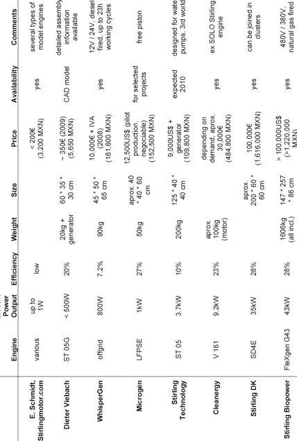
In Table 4.1 a benchmark of available (end of 2009) Stirling engines are provided. In the case of availability, an order can take several months to be considered. In the future, prices are supposed to drop, estimations of about 2,000 US$ per kWe can be found [27]. These prices must also be compared to the competitors: for
example, in spring 2010 a Capstone 30kW micro turbine costs about 45,000 to 60,000 US$, depending on the exact configuration.
![Figure 2.2 Free piston Stirling engine [4] and Alternative Stirling Engine Configurations [5],[2]](https://thumb-us.123doks.com/thumbv2/123dok_es/4464754.36012/17.612.49.493.100.332/figure-piston-stirling-engine-alternative-stirling-engine-configurations.webp)

![Figure 3.2 Vehicle 2 Grid [26]](https://thumb-us.123doks.com/thumbv2/123dok_es/4464754.36012/32.612.242.440.449.644/figure-vehicle-grid.webp)
![Figure 4.4 Transit Bus Configuration; DesignLine Bus [9]](https://thumb-us.123doks.com/thumbv2/123dok_es/4464754.36012/35.612.45.489.83.355/figure-transit-bus-configuration-designline-bus.webp)
![Figure 4.5 Solaris Urbino 18 Hybrid [33]](https://thumb-us.123doks.com/thumbv2/123dok_es/4464754.36012/36.612.160.519.490.702/figure-solaris-urbino-hybrid.webp)
![Figure 4.12 Chassis MB 1219 [40] and Ayco Magno 1040 SC bodywork](https://thumb-us.123doks.com/thumbv2/123dok_es/4464754.36012/45.612.135.407.147.364/figure-chassis-mb-ayco-magno-sc-bodywork.webp)