Corporate Headquarters
Cisco Systems, Inc. 170 West Tasman Drive San Jose, CA 95134-1706 USA
http://www.cisco.com Tel: 408 526-4000
800 553-NETS (6387) Fax: 408 526-4100
Catalyst 2950 Desktop Switch Software
Configuration Guide
THE SPECIFICATIONS AND INFORMATION REGARDING THE PRODUCTS IN THIS MANUAL ARE SUBJECT TO CHANGE WITHOUT NOTICE. ALL STATEMENTS, INFORMATION, AND RECOMMENDATIONS IN THIS MANUAL ARE BELIEVED TO BE ACCURATE BUT ARE PRESENTED WITHOUT WARRANTY OF ANY KIND, EXPRESS OR IMPLIED. USERS MUST TAKE FULL RESPONSIBILITY FOR THEIR APPLICATION OF ANY PRODUCTS. THE SOFTWARE LICENSE AND LIMITED WARRANTY FOR THE ACCOMPANYING PRODUCT ARE SET FORTH IN THE INFORMATION PACKET THAT SHIPPED WITH THE PRODUCT AND ARE INCORPORATED HEREIN BY THIS REFERENCE. IF YOU ARE UNABLE TO LOCATE THE SOFTWARE LICENSE OR LIMITED WARRANTY, CONTACT YOUR CISCO REPRESENTATIVE FOR A COPY.
The Cisco implementation of TCP header compression is an adaptation of a program developed by the University of California, Berkeley (UCB) as part of UCB’s public domain version of the UNIX operating system. All rights reserved. Copyright © 1981, Regents of the University of California.
NOTWITHSTANDING ANY OTHER WARRANTY HEREIN, ALL DOCUMENT FILES AND SOFTWARE OF THESE SUPPLIERS ARE PROVIDED “AS IS” WITH ALL FAULTS. CISCO AND THE ABOVE-NAMED SUPPLIERS DISCLAIM ALL WARRANTIES, EXPRESSED OR IMPLIED, INCLUDING, WITHOUT
LIMITATION, THOSE OF MERCHANTABILITY, FITNESS FOR A PARTICULAR PURPOSE AND NONINFRINGEMENT OR ARISING FROM A COURSE OF DEALING, USAGE, OR TRADE PRACTICE.
IN NO EVENT SHALL CISCO OR ITS SUPPLIERS BE LIABLE FOR ANY INDIRECT, SPECIAL, CONSEQUENTIAL, OR INCIDENTAL DAMAGES, INCLUDING, WITHOUT LIMITATION, LOST PROFITS OR LOSS OR DAMAGE TO DATA ARISING OUT OF THE USE OR INABILITY TO USE THIS MANUAL, EVEN IF CISCO OR ITS SUPPLIERS HAVE BEEN ADVISED OF THE POSSIBILITY OF SUCH DAMAGES.
Catalyst 2950 Desktop Switch Software Configuration Guide Copyright © 2001–2002, Cisco Systems, Inc.
All rights reserved.
CCIP, the Cisco Powered Network mark, the Cisco Systems Verified logo, Cisco Unity, Follow Me Browsing, FormShare, Internet Quotient, iQ Breakthrough, iQ Expertise, iQ FastTrack, the iQ Logo, iQ Net Readiness Scorecard, Networking Academy, ScriptShare, SMARTnet, TransPath, and Voice LAN are trademarks of Cisco Systems, Inc.; Changing the Way We Work, Live, Play, and Learn, Discover All That’s Possible, The Fastest Way to Increase Your Internet Quotient, and iQuick Study are service marks of Cisco Systems, Inc.; and Aironet, ASIST, BPX, Catalyst, CCDA, CCDP, CCIE, CCNA, CCNP, Cisco, the Cisco Certified Internetwork Expert logo, Cisco IOS, the Cisco IOS logo, Cisco Press, Cisco Systems, Cisco Systems Capital, the Cisco Systems logo, Empowering the Internet Generation, Enterprise/Solver, EtherChannel, EtherSwitch, Fast Step, GigaStack, IOS, IP/TV, LightStream, MGX, MICA, the Networkers logo, Network Registrar, Packet, PIX, Post-Routing, Pre-Routing, RateMUX, Registrar, SlideCast, StrataView Plus, Stratm, SwitchProbe, TeleRouter, and VCO are registered trademarks of Cisco Systems, Inc. and/or its affiliates in the U.S. and certain other countries.
C O N T E N T S
Preface
xxiAudience
xxiPurpose
xxiOrganization
xxiiConventions
xxivRelated Publications
xxvObtaining Documentation
xxvWorld Wide Web
xxvDocumentation CD-ROM
xxvOrdering Documentation
xxviDocumentation Feedback
xxviObtaining Technical Assistance
xxviCisco.com
xxviTechnical Assistance Center
xxviiCisco TAC Website
xxviiCisco TAC Escalation Center
xxviiiC H A P T E R 1
Overview
1-1Features
1-1Management Options
1-6Management Interface Options
1-6Advantages of Using CMS and Clustering Switches
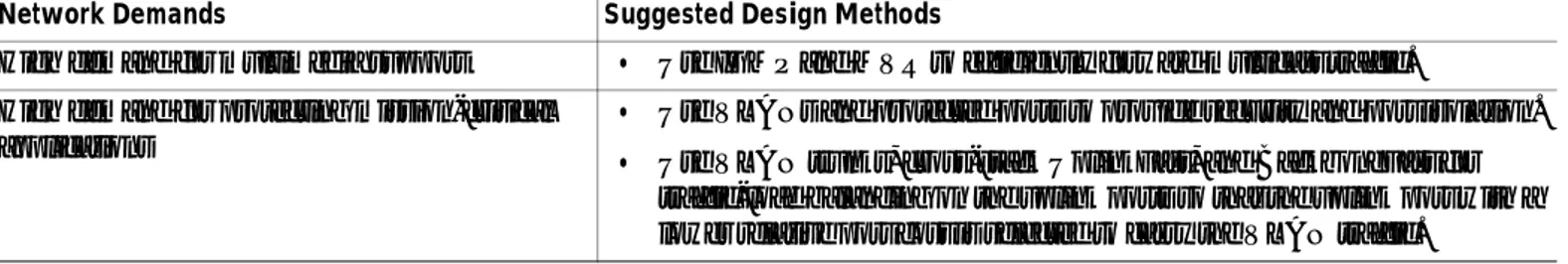
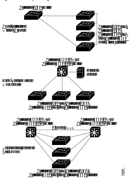
1-7Network Configuration Examples
1-8Design Concepts for Using the Switch
1-8Small to Medium-Sized Network Configuration
1-10Collapsed Backbone and Switch Cluster Configuration
1-12Large Campus Configuration
1-13Multidwelling Network Using Catalyst 2950 Switches
1-14Long-Distance, High-Bandwidth Transport Configuration
1-16C H A P T E R 2
Using the Command-Line Interface
2-1Contents
Abbreviating Commands
2-3Using no and default Forms of Commands
2-4Understanding CLI Messages
2-4Using Command History
2-5Changing the Command History Buffer Size
2-5Recalling Commands
2-5Disabling the Command History Feature
2-5Using Editing Features
2-6Enabling and Disabling Editing Features
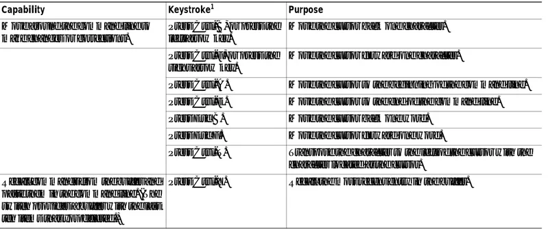
2-6Editing Commands through Keystrokes
2-6Editing Command Lines that Wrap
2-7Searching and Filtering Output of show and more Commands
2-8Accessing the CLI
2-9Accessing the CLI from a Browser
2-9Saving Configuration Changes
2-10Where to Go Next
2-10C H A P T E R 3
Getting Started with CMS
3-1Features
3-2Front Panel View
3-4Cluster Tree
3-5Front-Panel Images
3-6Redundant Power System LED
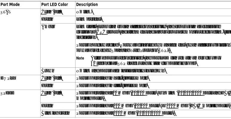
3-7Port Modes and LEDs
3-8VLAN Membership Modes
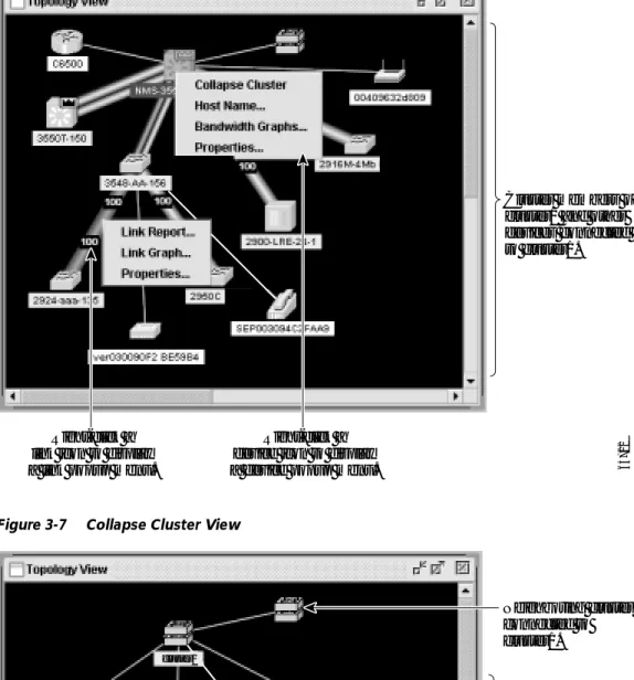
3-9Topology View
3-9Topology Icons
3-11Device and Link Labels
3-12Colors in the Topology View
3-13Topology Display Options
3-13Menus and Toolbar
3-14Menu Bar
3-14Toolbar
3-20Front Panel View Popup Menus
3-21Device Popup Menu
3-21Contents
Topology View Popup Menus
3-22Link Popup Menu
3-22Device Popup Menus
3-23Interaction Modes
3-25Guide Mode
3-25Expert Mode
3-25Wizards
3-25Tool Tips
3-26Online Help
3-26CMS Window Components
3-27Host Name List
3-27Tabs, Lists, and Tables
3-28Icons Used in Windows
3-28Buttons
3-28Accessing CMS
3-29Access Modes in CMS
3-30HTTP Access to CMS
3-30Verifying Your Changes
3-31Change Notification
3-31Error Checking
3-31Saving Your Changes
3-31Using Different Versions of CMS
3-32Where to Go Next
3-32C H A P T E R 4
Assigning the Switch IP Address and Default Gateway
4-1Understanding the Boot Process
4-1Assigning Switch Information
4-2Default Switch Information
4-3Understanding DHCP-Based Autoconfiguration
4-3DHCP Client Request Process
4-3Configuring the DHCP Server
4-5Configuring the TFTP Server
4-5Configuring the DNS
4-6Configuring the Relay Device
4-6Obtaining Configuration Files
4-7Example Configuration
4-8Contents
C H A P T E R 5
Configuring IE2100 CNS Agents
5-1Understanding IE2100 Series Configuration Registrar Software
5-1CNS Configuration Service
5-2CNS Event Service
5-3NameSpace Mapper
5-3What You Should Know About ConfigID, DeviceID, and Host Name
5-3ConfigID
5-3DeviceID
5-4Host Name and DeviceID
5-4Using Host Name, DeviceID, and ConfigID
5-4Understanding CNS Embedded Agents
5-5Initial Configuration
5-5Incremental (Partial) Configuration
5-6Synchronized Configuration
5-6Configuring CNS Embedded Agents
5-6Enabling Automated CNS Configuration
5-6Enabling the CNS Event Agent
5-8Enabling the CNS Configuration Agent
5-9Enabling an Initial Configuration
5-9Enabling a Partial Configuration
5-12Displaying CNS Configuration
5-12C H A P T E R 6
Clustering Switches
6-1Understanding Switch Clusters
6-2Command Switch Characteristics
6-3Standby Command Switch Characteristics
6-3Candidate Switch and Member Switch Characteristics
6-4Planning a Switch Cluster
6-5Automatic Discovery of Cluster Candidates and Members
6-5Discovery through CDP Hops
6-6Discovery through Non-CDP-Capable and Noncluster-Capable Devices
6-8Discovery through the Same Management VLAN
6-9Discovery through Different Management VLANs
6-10Discovery of Newly Installed Switches
6-12HSRP and Standby Command Switches
6-14Virtual IP Addresses
6-15Other Considerations for Cluster Standby Groups
6-15Contents
IP Addresses
6-17Host Names
6-18Passwords
6-18SNMP Community Strings
6-18TACACS+ and RADIUS
6-19Access Modes in CMS
6-19Management VLAN
6-20LRE Profiles
6-20Availability of Switch-Specific Features in Switch Clusters
6-21Creating a Switch Cluster
6-21Enabling a Command Switch
6-22Adding Member Switches
6-23Creating a Cluster Standby Group
6-25Verifying a Switch Cluster
6-27Using the CLI to Manage Switch Clusters
6-28Catalyst 1900 and Catalyst 2820 CLI Considerations
6-28Using SNMP to Manage Switch Clusters
6-29C H A P T E R 7
Administering the Switch
7-1Preventing Unauthorized Access to Your Switch
7-1Protecting Access to Privileged EXEC Commands
7-2Default Password and Privilege Level Configuration
7-3Setting or Changing a Static Enable Password
7-3Protecting Enable and Enable Secret Passwords with Encryption
7-4Setting a Telnet Password for a Terminal Line
7-5Configuring Username and Password Pairs
7-6Configuring Multiple Privilege Levels
7-7Setting the Privilege Level for a Command
7-7Changing the Default Privilege Level for Lines
7-8Logging into and Exiting a Privilege Level
7-9Controlling Switch Access with TACACS+
7-9Understanding TACACS+
7-9TACACS+ Operation
7-11Configuring TACACS+
7-12Default TACACS+ Configuration
7-12Identifying the TACACS+ Server Host and Setting the Authentication Key
7-12Configuring TACACS+ Login Authentication
7-13Contents
Displaying the TACACS+ Configuration
7-16Controlling Switch Access with RADIUS
7-17Understanding RADIUS
7-17RADIUS Operation
7-18Configuring RADIUS
7-19Default RADIUS Configuration
7-19Identifying the RADIUS Server Host
7-20Configuring RADIUS Login Authentication
7-22Defining AAA Server Groups
7-24Configuring RADIUS Authorization for Privileged EXEC Access and Network Services
7-26Starting RADIUS Accounting
7-27Configuring Settings for All RADIUS Servers
7-28Configuring the Switch to Use Vendor-Specific RADIUS Attributes
7-28Configuring the Switch for Vendor-Proprietary RADIUS Server Communication
7-29Displaying the RADIUS Configuration
7-30Configuring the Switch for Local Authentication and Authorization
7-31Configuring the Switch for Secure Shell
7-32Understanding SSH
7-32Configuring SSH
7-32Managing the System Time and Date
7-33Understanding the System Clock
7-33Understanding Network Time Protocol
7-33Configuring NTP
7-35Default NTP Configuration
7-36Configuring NTP Authentication
7-36Configuring NTP Associations
7-37Configuring NTP Broadcast Service
7-38Configuring NTP Access Restrictions
7-39Configuring the Source IP Address for NTP Packets
7-41Displaying the NTP Configuration
7-42Configuring Time and Date Manually
7-42Setting the System Clock
7-43Displaying the Time and Date Configuration
7-43Configuring the Time Zone
7-44Configuring Summer Time (Daylight Saving Time)
7-45Configuring a System Name and Prompt
7-47Default System Name and Prompt Configuration
7-47Contents
Understanding DNS
7-48Default DNS Configuration
7-49Setting Up DNS
7-49Displaying the DNS Configuration
7-50Creating a Banner
7-50Default Banner Configuration
7-50Configuring a Message-of-the-Day Login Banner
7-50Configuring a Login Banner
7-52Managing the MAC Address Table
7-52Building the Address Table
7-53MAC Addresses and VLANs
7-53Default MAC Address Table Configuration
7-54Changing the Address Aging Time
7-54Removing Dynamic Address Entries
7-55Configuring MAC Address Notification Traps
7-55Adding and Removing Static Address Entries
7-57Configuring Static Addresses for EtherChannel Port Groups
7-58Adding and Removing Secure Addresses
7-58Displaying Address Table Entries
7-59Managing the ARP Table
7-59C H A P T E R 8
Configuring 802.1X Port-Based Authentication
8-1Understanding 802.1X Port-Based Authentication
8-1Device Roles
8-2Authentication Initiation and Message Exchange
8-3Ports in Authorized and Unauthorized States
8-4Supported Topologies
8-5Configuring 802.1X Authentication
8-6Default 802.1X Configuration
8-6802.1X Configuration Guidelines
8-7Enabling 802.1X Authentication
8-8Configuring the Switch-to-RADIUS-Server Communication
8-9Enabling Periodic Re-Authentication
8-10Manually Re-Authenticating a Client Connected to a Port
8-11Changing the Quiet Period
8-11Changing the Switch-to-Client Retransmission Time
8-12Setting the Switch-to-Client Frame-Retransmission Number
8-13Contents
Resetting the 802.1X Configuration to the Default Values
8-14Displaying 802.1X Statistics and Status
8-14C H A P T E R 9
Configuring Interface Characteristics
9-1Understanding Interface Types
9-1Port-Based VLANs
9-1Switch Ports
9-2Access Ports
9-2Trunk Ports
9-2EtherChannel Port Groups
9-3Connecting Interfaces
9-3Using the Interface Command
9-4Procedures for Configuring Interfaces
9-5Configuring a Range of Interfaces
9-7Configuring and Using Interface Range Macros
9-9Configuring Layer 2 Interfaces
9-10Default Layer 2 Ethernet Interface Configuration
9-11Configuring the Port Speed and Duplex Mode
9-11Configuration Guidelines
9-12Connecting to Devices That Do Not Autonegotiate
9-12Setting Speed and Duplex Parameters
9-12Configuring IEEE 802.3X Flow Control on Gigabit Ethernet Ports
9-14Adding a Description for an Interface
9-15Monitoring and Maintaining the Interface
9-16Monitoring Interface and Controller Status
9-16Clearing and Resetting Interfaces and Counters
9-18Shutting Down and Restarting the Interface
9-19C H A P T E R 10
Configuring STP
10-1Understanding Spanning-Tree Features
10-1STP Overview
10-2Supported Spanning-Tree Instances
10-2Bridge Protocol Data Units
10-2Election of the Root Switch
10-3Bridge ID, Switch Priority, and Extended System ID
10-4Spanning-Tree Timers
10-4Contents
Spanning-Tree Interface States
10-5Blocking State
10-7Listening State
10-7Learning State
10-7Forwarding State
10-7Disabled State
10-8Spanning-Tree Address Management
10-8STP and IEEE 802.1Q Trunks
10-8Spanning Tree and Redundant Connectivity
10-8Accelerated Aging to Retain Connectivity
10-9Configuring Spanning-Tree Features
10-9Default STP Configuration
10-10STP Configuration Guidelines
10-10Disabling STP
10-11Configuring the Root Switch
10-12Configuring a Secondary Root Switch
10-13Configuring the Port Priority
10-14Configuring the Path Cost
10-15Configuring the Switch Priority of a VLAN
10-17Configuring the Hello Time
10-18Configuring the Forwarding-Delay Time for a VLAN
10-18Configuring the Maximum-Aging Time for a VLAN
10-19Configuring STP for Use in a Cascaded Stack
10-20Displaying Spanning-Tree Status
10-21C H A P T E R 11
Configuring RSTP and MSTP
11-1Understanding RSTP
11-2Port Roles and the Active Topology
11-2Rapid Convergence
11-3Synchronization of Port Roles
11-4Bridge Protocol Data Unit Format and Processing
11-5Processing Superior BPDU Information
11-6Processing Inferior BPDU Information
11-6Topology Changes
11-6Understanding MSTP
11-7Multiple Spanning-Tree Regions
11-7IST, CIST, and CST
11-8Contents
Hop Count
11-10Boundary Ports
11-10Interoperability with 802.1D STP
11-10Configuring RSTP and MSTP Features
11-11Default RSTP and MSTP Configuration
11-12RSTP and MSTP Configuration Guidelines
11-12Specifying the MST Region Configuration and Enabling MSTP
11-13Configuring the Root Switch
11-14Configuring a Secondary Root Switch
11-16Configuring the Port Priority
11-17Configuring the Path Cost
11-18Configuring the Switch Priority
11-19Configuring the Hello Time
11-19Configuring the Forwarding-Delay Time
11-20Configuring the Maximum-Aging Time
11-21Configuring the Maximum-Hop Count
11-21Specifying the Link Type to Ensure Rapid Transitions
11-22Restarting the Protocol Migration Process
11-22Displaying the MST Configuration and Status
11-23C H A P T E R 12
Configuring Optional Spanning-Tree Features
12-1Understanding Optional Spanning-Tree Features
12-1Understanding Port Fast
12-2Understanding BPDU Guard
12-3Understanding BPDU Filtering
12-3Understanding UplinkFast
12-4Understanding Cross-Stack UplinkFast
12-5How CSUF Works
12-6Events that Cause Fast Convergence
12-7Limitations
12-8Connecting the Stack Ports
12-8Understanding BackboneFast
12-10Understanding Root Guard
12-12Understanding Loop Guard
12-13Configuring Optional Spanning-Tree Features
12-13Default Optional Spanning-Tree Configuration
12-14Enabling Port Fast
12-14Contents
Enabling UplinkFast for Use with Redundant Links
12-17Enabling Cross-Stack UplinkFast
12-18Enabling BackboneFast
12-19Enabling Root Guard
12-19Enabling Loop Guard
12-20Displaying the Spanning-Tree Status
12-21C H A P T E R 13
Configuring VLANs
13-1Understanding VLANs
13-1Supported VLANs
13-2Management VLANs
13-3Determining the Management VLAN for a New Switch
13-4Changing the Management VLAN for a Cluster
13-4VLAN Port Membership Modes
13-5Configuring Normal-Range VLANs
13-6Token Ring VLANs
13-7Configuration Guidelines for Normal-Range VLANs
13-7VLAN Configuration Mode Options
13-8VLAN Configuration in config-vlan Mode
13-8VLAN Configuration in VLAN Configuration Mode
13-8Saving VLAN Configuration
13-9Default Ethernet VLAN Configuration
13-10Creating or Modifying an Ethernet VLAN
13-10Deleting a VLAN
13-12Assigning Static-Access Ports to a VLAN
13-13Configuring Extended-Range VLANs
13-14Default VLAN Configuration
13-14Configuration Guidelines for Extended-Range VLANs
13-15Creating an Extended-Range VLAN
13-15Displaying VLANs
13-16Configuring VLAN Trunks
13-18Trunking Overview
13-18802.1Q Configuration Considerations
13-20Default Layer 2 Ethernet Interface VLAN Configuration
13-21Configuring an Ethernet Interface as a Trunk Port
13-21Interaction with Other Features
13-21Configuring a Trunk Port
13-22Contents
Changing the Pruning-Eligible List
13-24Configuring the Native VLAN for Untagged Traffic
13-25Load Sharing Using STP
13-26Load Sharing Using STP Port Priorities
13-26Load Sharing Using STP Path Cost
13-28Configuring VMPS
13-30Understanding VMPS
13-30Dynamic Port VLAN Membership
13-31VMPS Database Configuration File
13-31Default VMPS Configuration
13-33VMPS Configuration Guidelines
13-33Configuring the VMPS Client
13-34Entering the IP Address of the VMPS
13-34Configuring Dynamic Access Ports on VMPS Clients
13-34Reconfirming VLAN Memberships
13-35Changing the Reconfirmation Interval
13-35Changing the Retry Count
13-36Monitoring the VMPS
13-36Troubleshooting Dynamic Port VLAN Membership
13-37VMPS Configuration Example
13-37C H A P T E R 14
Configuring VTP
14-1Understanding VTP
14-1The VTP Domain
14-2VTP Modes
14-3VTP Advertisements
14-3VTP Version 2
14-4VTP Pruning
14-4Configuring VTP
14-6Default VTP Configuration
14-6VTP Configuration Options
14-7VTP Configuration in Privileged EXEC and Global Configuration Modes
14-7VTP Configuration in VLAN Configuration Mode
14-7VTP Configuration Guidelines
14-8Domain Names
14-8Passwords
14-8Upgrading from Previous Software Releases
14-8Contents
Configuring a VTP Server
14-9Configuring a VTP Client
14-11Disabling VTP (VTP Transparent Mode)
14-12Enabling VTP Version 2
14-13Enabling VTP Pruning
14-14Adding a VTP Client Switch to a VTP Domain
14-15Monitoring VTP
14-16C H A P T E R 15
Configuring Voice VLAN
15-1Understanding Voice VLAN
15-1Configuring Voice VLAN
15-2Default Voice VLAN Configuration
15-2Configuration Guidelines
15-3Configuring a Port to Connect to a Cisco 7960 IP Phone
15-3Configuring Ports to Carry Voice Traffic in 802.1Q Frames
15-4Configuring Ports to Carry Voice Traffic in 802.1P Priority Tagged Frames
15-4Overriding the CoS Priority of Incoming Data Frames
15-5Configuring the IP Phone to Trust the CoS Priority of Incoming Data Frames
15-5Displaying Voice VLAN
15-6C H A P T E R 16
Configuring IGMP Snooping and MVR
16-1Understanding IGMP Snooping
16-1Joining a Multicast Group
16-2Leaving a Multicast Group
16-4Immediate-Leave Processing
16-4Configuring IGMP Snooping
16-5Default IGMP Snooping Configuration
16-5Enabling or Disabling IGMP Snooping
16-5Setting the Snooping Method
16-6Configuring a Multicast Router Port
16-7Configuring a Host Statically to Join a Group
16-8Enabling IGMP Immediate-Leave Processing
16-9Displaying IGMP Snooping Information
16-10Understanding Multicast VLAN Registration
16-11Using MVR in a Multicast Television Application
16-11Configuring MVR
16-13Contents
Configuring MVR Global Parameters
16-14Configuring MVR Interfaces
16-15Displaying MVR Information
16-17Configuring IGMP Filtering
16-18Default IGMP Filtering Configuration
16-19Configuring IGMP Profiles
16-19Applying IGMP Profiles
16-20Setting the Maximum Number of IGMP Groups
16-21Displaying IGMP Filtering Configuration
16-22C H A P T E R 17
Configuring Port-Based Traffic Control
17-1Configuring Storm Control
17-1Disabling Storm Control
17-2Configuring Protected Ports
17-3Configuring Port Security
17-3Defining the Maximum Secure Address Count
17-4Enabling Port Security
17-5Disabling Port Security
17-5Configuring and Enabling Port Security Aging
17-6Displaying Port-Based Traffic Control Settings
17-7C H A P T E R 18
Configuring UDLD
18-1Understanding UDLD
18-1Configuring UDLD
18-3Default UDLD Configuration
18-3Enabling UDLD Globally
18-3Enabling UDLD on an Interface
18-4Resetting an Interface Shut Down by UDLD
18-4Displaying UDLD Status
18-5C H A P T E R 19
Configuring CDP
19-1Understanding CDP
19-1Configuring CDP
19-2Default CDP Configuration
19-2Configuring the CDP Characteristics
19-2Disabling and Enabling CDP
19-3Contents
C H A P T E R 20
Configuring SPAN
20-1Understanding SPAN
20-1SPAN Concepts and Terminology
20-2SPAN Session
20-2Traffic Types
20-2Source Port
20-3Destination Port
20-3SPAN Traffic
20-4SPAN Interaction with Other Features
20-4Configuring SPAN
20-5SPAN Configuration Guidelines
20-5Creating a SPAN Session and Specifying Ports to Monitor
20-6Removing Ports from a SPAN Session
20-7Displaying SPAN Status
20-8C H A P T E R 21
Configuring System Message Logging
21-1Understanding System Message Logging
21-1Configuring System Message Logging
21-2System Log Message Format
21-2Default System Message Logging Configuration
21-3Disabling and Enabling Message Logging
21-4Setting the Message Display Destination Device
21-4Synchronizing Log Messages
21-6Enabling and Disabling Timestamps on Log Messages
21-7Enabling and Disabling Sequence Numbers in Log Messages
21-8Defining the Message Severity Level
21-8Limiting Syslog Messages Sent to the History Table and to SNMP
21-10Configuring UNIX Syslog Servers
21-10Logging Messages to a UNIX Syslog Daemon
21-11Configuring the UNIX System Logging Facility
21-11Displaying the Logging Configuration
21-12C H A P T E R 22
Configuring SNMP
22-1Understanding SNMP
22-1SNMP Versions
22-2SNMP Manager Functions
22-2Contents
Configuring SNMP
22-4Default SNMP Configuration
22-4Disabling the SNMP Agent
22-5Configuring Community Strings
22-5Configuring Trap Managers and Enabling Traps
22-7Setting the Agent Contact and Location Information
22-9Limiting TFTP Servers Used Through SNMP
22-9SNMP Examples
22-10Displaying SNMP Status
22-10C H A P T E R 23
Configuring Network Security with ACLs
23-1Understanding ACLs
23-1ACLs
23-2Handling Fragmented and Unfragmented Traffic
23-3Understanding Access Control Parameters
23-4Guidelines for Configuring ACLs on the Catalyst 2950 Switches
23-5Configuring ACLs
23-6Unsupported Features
23-6Creating Standard and Extended IP ACLs
23-7ACL Numbers
23-7Creating a Numbered Standard ACL
23-8Creating a Numbered Extended ACL
23-9Creating Named Standard and Extended ACLs
23-12Including Comments About Entries in ACLs
23-14Applying the ACL to an Interface or Terminal Line
23-15Displaying ACLs
23-16Displaying Access Groups
23-17Examples for Compiling ACLs
23-18Creating Named MAC Extended ACLs
23-20Creating MAC Access Groups
23-21C H A P T E R 24
Configuring QoS
24-1Understanding QoS
24-2Basic QoS Model
24-3Classification
24-4Classification Based on QoS ACLs
24-5Classification Based on Class Maps and Policy Maps
24-5Contents
Queueing and Scheduling
24-8How Class of Service Works
24-8Port Priority
24-8Port Scheduling
24-8CoS and WRR
24-8Configuring QoS
24-9Default QoS Configuration
24-9Configuration Guidelines
24-10Configuring Classification Using Port Trust States
24-10Configuring the Trust State on Ports within the QoS Domain
24-11Configuring the CoS Value for an Interface
24-13Configuring a QoS Policy
24-13Classifying Traffic by Using ACLs
24-14Classifying Traffic by Using Class Maps
24-17Classifying, Policing, and Marking Traffic by Using Policy Maps
24-18Configuring CoS Maps
24-21Configuring the CoS-to-DSCP Map
24-21Configuring the DSCP-to-CoS Map
24-22Configuring CoS and WRR
24-23CLI: Configuring CoS Priority Queues
24-24Configuring WRR
24-24Displaying QoS Information
24-25QoS Configuration Examples
24-25QoS Configuration for the Common Wiring Closet
24-26QoS Configuration for the Intelligent Wiring Closet
24-27C H A P T E R 25
Configuring EtherChannels
25-1Understanding EtherChannels
25-1Understanding Port-Channel Interfaces
25-2Understanding the Port Aggregation Protocol
25-3PAgP Modes
25-3Physical Learners and Aggregate-Port Learners
25-4PAgP Interaction with Other Features
25-5Understanding Load Balancing and Forwarding Methods
25-5Default EtherChannel Configuration
25-6EtherChannel Configuration Guidelines
25-7Configuring EtherChannels
25-7Contents
Configuring the PAgP Learn Method and Priority
25-10Displaying EtherChannel and PAgP Status
25-10C H A P T E R 26
Troubleshooting
26-1Avoiding Configuration Conflicts
26-1Avoiding Autonegotiation Mismatches
26-2GBIC Security and Identification
26-2Troubleshooting CMS Sessions
26-3Copying Configuration Files to Troubleshoot Configuration Problems
26-4Using Recovery Procedures
26-5Recovering from Lost Member Connectivity
26-5Recovering from a Command Switch Failure
26-6Replacing a Failed Command Switch with a Cluster Member
26-6Replacing a Failed Command Switch with Another Switch
26-8Recovering from a Failed Command Switch Without HSRP
26-9Recovering from a Lost or Forgotten Password
26-9Recovering from Corrupted Software
26-11Using Debug Commands
26-11Enabling Debugging on a Specific Feature
26-12Enabling All-System Diagnostics
26-12Redirecting Debug and Error Message Output
26-13A P P E N D I X A
Supported MIBs
A-1MIB List
A-1Using FTP to Access the MIB Files
A-2Preface
Audience
The Catalyst 2950 Desktop Switch Software Configuration Guide is for the network manager responsible for configuring the Catalyst 2950 switches, hereafter referred to as the switches. Before using this guide, you should be familiar with the concepts and terminology of Ethernet and local area networking.
Purpose
This guide provides information about configuring and troubleshooting a switch or switch clusters. It includes descriptions of the management interface options and the features supported by the switch software. The Catalyst 2950 switch is supported by either the standard software image (SI) or the enhanced software image (EI). The enhanced software image provides a richer set of features, including access control lists (ACLs), enhanced quality of service (QoS) features, the Secure Shell Protocol, extended-range VLANs, IEEE 802.1W Rapid Spanning Tree Protocol (STP), and the IEEE 802.1S Multiple STP.
The enhanced software image supports these switches:
• Catalyst 2950C-24
• Catalyst 2950G-12-EI
• Catalyst 2950G-24-EI
• Catalyst 2950G-24-EI-DC
• Catalyst 2950G-48-EI
• Catalyst 2950T-24
The standard software image supports these switches:
• Catalyst 2950-12
• Catalyst 2950-24
Use this guide with other documents for information about these topics:
• Requirements—This guide assumes that you have met the hardware and software requirements and cluster compatibility requirements described in the release notes.
Preface Organization
• Cluster Management Suite (CMS) information—This guide provides an overview of the CMS web-based, switch management interface. For information about CMS requirements and the procedures for browser and plug-in configuration and accessing CMS, refer to the release notes. For CMS field-level window descriptions and procedures, refer to the CMS online help.
• Cluster configuration—This guide provides information about planning for, creating, and
maintaining switch clusters. Because configuring switch clusters is most easily performed through CMS, this guide does not provide the command-line interface (CLI) procedures. For the cluster commands, refer to the Catalyst 2950 Desktop Switch Command Reference.
• CLI command information—This guide provides an overview for using the CLI. For complete syntax and usage information about the commands that have been specifically created or changed for the Catalyst 2950 switches, refer to the Catalyst 2950 Desktop Switch Command Reference.
This guide does not describe system messages you might encounter or how to install your switch. For more information, refer to the Catalyst 2950 Desktop Switch System Message Guide for this release and to the Catalyst 2950 Desktop Switch Hardware Installation Guide.
Note This guide does not repeat the concepts and CLI procedures provided in the standard Cisco IOS Release 12.1 documentation. For information about the standard IOS Release 12.1 commands, refer to the IOS documentation set available from the Cisco.com home page at Service and Support >
Technical Documents. On the Cisco Product Documentation home page, select Release 12.1 from the Cisco
IOS Software drop-down list.
Organization
This guide is organized into these chapters:
Chapter 1, “Overview,”lists the software features of this release and provides examples of how the switch can be deployed in a network.
Chapter 2, “Using the Command-Line Interface,”describes how to access the command modes, use the command-line interface (CLI), and describes CLI messages that you might receive. It also describes how to get help, abbreviate commands, use no and default forms of commands, use command history and editing features, and how to search and filter the output of show and more commands.
Chapter 3, “Getting Started with CMS,”describes the Cluster Management Suite (CMS) web-based, switch management interface. For information on configuring your web browser and accessing CMS, refer to the release notes. For field-level descriptions of all CMS windows and procedures for using the CMS windows, refer to the online help.
Chapter 4, “Assigning the Switch IP Address and Default Gateway,”describes how to create the initial switch configuration (for example, assign the switch IP address and default gateway information) by using a variety of automatic and manual methods.
Chapter 5, “Configuring IE2100 CNS Agents,”describes how to configure Cisco Intelligence Engine 2100 (IE2100) Series Cisco Networking Services (CNS) embedded agents on your switch. By using the
IE2100 Series Configuration Registrar network management application, you can automate initial
configurations and configuration updates by generating switch-specific configuration changes, sending them to the switch, executing the configuration change, and logging the results.
Preface
Organization
Chapter 7, “Administering the Switch,”describes how to perform one-time operations to administer your switch. It describes how to prevent unauthorized access to your switch through the use of passwords, privilege levels, the Terminal Access Controller Access Control System Plus (TACACS+), the Remote Authentication Dial-In User Service (RADIUS) and the Secure Shell (SSH) Protocol. It also describes how to set the system date and time, set system name and prompt, create a login banner, and how to manage the MAC address and ARP tables.
Chapter 8, “Configuring 802.1X Port-Based Authentication,”describes how to configure 802.1X port-based authentication to prevent unauthorized devices (clients) from gaining access to the network. As LANs extend to hotels, airports, and corporate lobbies, insecure environments could be created.
Chapter 9, “Configuring Interface Characteristics,”defines the types of interfaces on the switch. It describes the interface global configuration command and provides procedures for configuring physical interfaces.
Chapter 10, “Configuring STP,”describes how to configure the Spanning Tree Protocol (STP) on your switch.
Chapter 11, “Configuring RSTP and MSTP,”describes how to configure the Cisco implementation of the IEEE 802.1W Rapid STP (RSTP) and the IEEE 802.1S Multiple STP (MSTP) on your switch. RSTP provides rapid convergence, and MSTP enables VLANs to be grouped into a spanning-tree instance.
Chapter 12, “Configuring Optional Spanning-Tree Features,”describes how to configure optional spanning-tree features that can be used when your switch is running the per-VLAN spanning-tree (PVST) or the MSTP.
Chapter 13, “Configuring VLANs,”describes how to create and maintain VLANs. It includes information about the VLAN database, VLAN configuration modes, extended-range VLANs, VLAN trunks, and the VLAN Membership Policy Server (VMPS).
Chapter 14, “Configuring VTP,”describes how to use the VLAN Trunking Protocol (VTP) VLAN database for managing VLANs. It includes VTP characteristics and configuration.
Chapter 15, “Configuring Voice VLAN,”describes how to configure voice VLAN on the switch for a connection to an IP phone.
Chapter 16, “Configuring IGMP Snooping and MVR,”describes how to configure Internet Group Management Protocol (IGMP) snooping. It also describes Multicast VLAN Registration (MVR), a local IGMP snooping feature available on the switch, and how to use IGMP filtering to control multicast group membership.
Chapter 17, “Configuring Port-Based Traffic Control,”describes how to reduce traffic storms by setting broadcast, multicast, and unicast storm-control threshold levels; how to protect ports from receiving traffic from other ports on a switch; how to configure port security by using secure MAC addresses; and how to set the aging time for all secure addresses.
Chapter 19, “Configuring CDP,”describes how to configure Cisco Discovery Protocol (CDP) on your switch.
Chapter 20, “Configuring SPAN,”describes how to configure Switch Port Analyzer (SPAN), which selects network traffic for analysis by a network analyzer such as a SwitchProbe device or other Remote Monitoring (RMON) probe. SPAN mirrors traffic received or sent (or both) on a source port, or traffic received on one or more source ports or source VLANs, to a destination port.
Preface Conventions
Chapter 22, “Configuring SNMP,”describes how to configure the Simple Network Management Protocol (SNMP). It describes how to configure community strings, enable trap managers and traps, set the agent contact and location information, and how to limit TFTP servers used through SNMP.
Chapter 23, “Configuring Network Security with ACLs,”provides the considerations and CLI procedures for configuring network security by using access control lists (ACLs). It describes how to apply ACLs to interfaces and provides examples. The online help provides the CMS procedures.
Chapter 24, “Configuring QoS,”provides the considerations and CLI procedures for configuring quality of service (QoS). With this feature, you can provide preferential treatment to certain types of traffic. The online help provides the CMS procedures.
Chapter 25, “Configuring EtherChannels,”describes how to bundle a set of individual ports into a single logical link on the interfaces.
Chapter 26, “Troubleshooting,”describes how to identify and resolve software problems related to the IOS software.
Appendix A, “Supported MIBs,”lists the supported MIBs for this release and how to use FTP to access the MIB files.
Conventions
This guide uses these conventions to convey instructions and information:
Command descriptions use these conventions:
• Commands and keywords are in boldface text.
• Arguments for which you supply values are in italic.
• Square brackets ([ ]) indicate optional elements.
• Braces ({ }) group required choices, and vertical bars ( | ) separate the alternative elements.
• Braces and vertical bars within square brackets ([{ | }]) indicate a required choice within an optional element.
Interactive examples use these conventions:
• Terminal sessions and system displays are inscreenfont.
• Information you enter is inboldface screenfont.
• Nonprinting characters, such as passwords or tabs, are in angle brackets (< >). Notes, cautions, and tips use these conventions and symbols:
Note Means reader take note. Notes contain helpful suggestions or references to materials not contained in this manual.
Caution Means reader be careful. In this situation, you might do something that could result in equipment damage or loss of data.
Preface
Related Publications
Related Publications
These documents provide complete information about the switch and are available from this Cisco.com site:
http://www.cisco.com/univercd/cc/td/doc/product/lan/cat2950/index.htm
You can order printed copies of documents with a DOC-xxxxxx= number from the Cisco.com sites and from the telephone numbers listed in the“Obtaining Documentation” section on page xxv.
• Release Notes for the Catalyst 2950 Switch (not orderable but is available on Cisco.com)
Note Switch requirements and procedures for initial configurations and software upgrades tend to change and therefore appear only in the release notes. Before installing, configuring, or upgrading the switch, refer to the release notes on Cisco.com for the latest information.
• Catalyst 2950 Desktop Switch Software Configuration Guide (order number DOC-7811380=)
• Catalyst 2950 Desktop Switch Command Reference (order number DOC-7811381=)
• Catalyst 2950 Desktop Switch System Message Guide (order number DOC-7814233=)
• Catalyst 2950 Desktop Switch Hardware Installation Guide (order number DOC-7811157=)
• Catalyst GigaStack Gigabit Interface Converter Hardware Installation Guide
(order number DOC-786460=)
• CWDM Passive Optical System Installation Note (not orderable but is available on Cisco.com)
• 1000BASE-T GBIC Installation Notes (not orderable but is available on Cisco.com)
Obtaining Documentation
The following sections explain how to obtain documentation from Cisco Systems.
World Wide Web
You can access the most current Cisco documentation on the World Wide Web at the following URL:
http://www.cisco.com
Translated documentation is available at the following URL:
http://www.cisco.com/public/countries_languages.shtml
Documentation CD-ROM
Preface Obtaining Technical Assistance
Ordering Documentation
Cisco documentation is available in the following ways:
• Registered Cisco.com users (Cisco direct customers) can order Cisco product documentation from the Networking Products MarketPlace:
http://www.cisco.com/cgi-bin/order/order_root.pl
• Registered Cisco.com users can order the Documentation CD-ROM through the online Subscription Store:
http://www.cisco.com/go/subscription
• Nonregistered Cisco.com users can order documentation through a local account representative by calling Cisco corporate headquarters (California, USA) at 408 526-7208 or, elsewhere in North America, by calling 800 553-NETS (6387).
Documentation Feedback
If you are reading Cisco product documentation on the World Wide Web, you can send us your comments by completing the online survey. When you display the document listing for this platform, click Give Us
Your Feedback. After you display the survey, select the manual that you wish to comment on. Click Submit to send your comments to the Cisco documentation group.
You can e-mail your comments to bug-doc@cisco.com.
To submit your comments by mail, use the response card behind the front cover of your document, or write to the following address:
Cisco Systems
Attn: Document Resource Connection 170 West Tasman Drive
San Jose, CA 95134-9883
We appreciate your comments.
Obtaining Technical Assistance
Cisco provides Cisco.com as a starting point for all technical assistance. Customers and partners can obtain documentation, troubleshooting tips, and sample configurations from online tools by using the Cisco Technical Assistance Center (TAC) website. Cisco.com registered users have complete access to the technical support resources on the Cisco TAC website.
Cisco.com
Preface
Obtaining Technical Assistance
Cisco.com is a highly integrated Internet application and a powerful, easy-to-use tool that provides a broad range of features and services to help you to
• Streamline business processes and improve productivity
• Resolve technical issues with online support
• Download and test software packages
• Order Cisco learning materials and merchandise
• Register for online skill assessment, training, and certification programs
You can self-register on Cisco.com to obtain customized information and service. To access Cisco.com, go to the following URL:
http://www.cisco.com
Technical Assistance Center
The Cisco TAC is available to all customers who need technical assistance with a Cisco product, technology, or solution. Two types of support are available through the Cisco TAC: the Cisco TAC website and the Cisco TAC Escalation Center.
Inquiries to Cisco TAC are categorized according to the urgency of the issue:
• Priority level 4 (P4)—You need information or assistance concerning Cisco product capabilities, product installation, or basic product configuration.
• Priority level 3 (P3)—Your network performance is degraded. Network functionality is noticeably impaired, but most business operations continue.
• Priority level 2 (P2)—Your production network is severely degraded, affecting significant aspects of business operations. No workaround is available.
• Priority level 1 (P1)—Your production network is down, and a critical impact to business operations will occur if service is not restored quickly. No workaround is available.
Which Cisco TAC resource you choose is based on the priority of the problem and the conditions of service contracts, when applicable.
Cisco TAC Website
The Cisco TAC website allows you to resolve P3 and P4 issues yourself, saving both cost and time. The site provides around-the-clock access to online tools, knowledge bases, and software. To access the Cisco TAC website, go to the following URL:
http://www.cisco.com/tac
All customers, partners, and resellers who have a valid Cisco services contract have complete access to the technical support resources on the Cisco TAC website. The Cisco TAC website requires a Cisco.com login ID and password. If you have a valid service contract but do not have a login ID or password, go to the following URL to register:
Preface Obtaining Technical Assistance
If you cannot resolve your technical issues by using the Cisco TAC website, and you are a Cisco.com registered user, you can open a case online by using the TAC Case Open tool at the following URL:
http://www.cisco.com/tac/caseopen
If you have Internet access, it is recommended that you open P3 and P4 cases through the Cisco TAC website.
Cisco TAC Escalation Center
The Cisco TAC Escalation Center addresses issues that are classified as priority level 1 or priority level 2; these classifications are assigned when severe network degradation significantly impacts business operations. When you contact the TAC Escalation Center with a P1 or P2 problem, a Cisco TAC engineer will automatically open a case.
To obtain a directory of toll-free Cisco TAC telephone numbers for your country, go to the following URL:
http://www.cisco.com/warp/public/687/Directory/DirTAC.shtml
C H A P T E R
1
Overview
This chapter provides these topics about the Catalyst 2950 switch software:
• Features
• Management options
• Examples of the Catalyst 2950 switches in different network topologies
Features
The Catalyst 2950 software supports the switches listed in the Release Notes for the Catalyst 2950
Cisco IOS Release 12.1(9)EA1.Table 1-1describes the features supported in this release.
Note Some features require that you have the enhanced software image installed on your switch. See the
Chapter 1 Overview Features
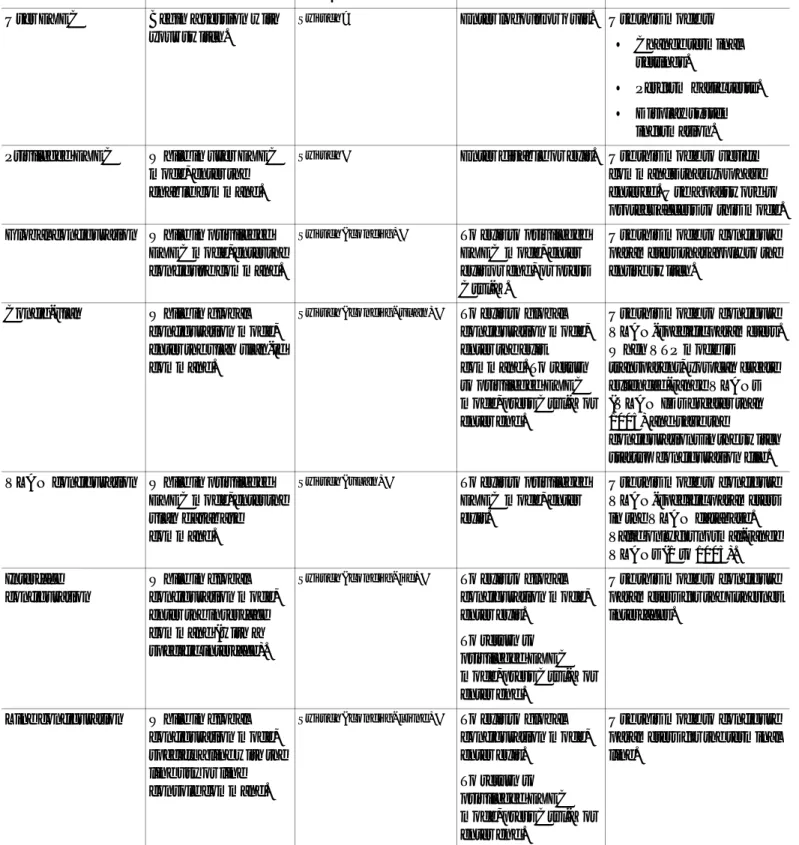
Table 1-1 Features
Ease of Use and Ease of Deployment
• Cluster Management Suite (CMS) software for simplified switch and switch cluster management through a web browser, such as Netscape Communicator or Microsoft Internet Explorer, from anywhere in your intranet
• Switch clustering technology used with CMS for
– Unified configuration, monitoring, authentication, and software upgrade of multiple switches (refer to the release notes for a list of eligible cluster members).
– Automatic discovery of candidate switches and creation of clusters of up to 16 switches that can be managed through a single IP address.
– Extended discovery of cluster candidates that are not directly connected to the command switch.
• Hot Standby Router Protocol (HSRP) for command-switch redundancy. The redundant command switches used for HSRP must have compatible software releases.
Note See the“Advantages of Using CMS and Clustering Switches” section on page 1-7. Refer to the release notes for the CMS, cluster hardware, software, and browser requirements.
Performance
• Autosensing of speed on the 10/100 ports and autonegotiation of duplex mode on all switch ports for optimizing bandwidth
• IEEE 802.3X flow control on Gigabit Ethernet ports operating in full-duplex mode
• Fast EtherChannel and Gigabit EtherChannel for enhanced fault tolerance and for providing up to 2 Gbps of bandwidth between switches, routers, and servers
• Support for mini-jumbo frames. The Catalyst 2950 switches running Cisco IOS Release12.1(6)EA2 or later support frame sizes 1500 to 1530 bytes
• Per-port broadcast storm control for preventing faulty end stations from degrading overall system performance with broadcast storms
• Port Aggregation Protocol (PAgP) for automatic creation of EtherChannel links
• Internet Group Management Protocol (IGMP) snooping support to limit flooding of IP multicast traffic
• Multicast VLAN registration (MVR) to continuously send multicast streams in a multicast VLAN, but to isolate the streams from subscriber VLANs for bandwidth and security reasons
• IGMP filtering for controlling the set of multicast groups to which hosts on a switch port can belong
• Protected port (private VLAN edge port) option for restricting the forwarding of traffic to designated ports on the same switch
Chapter 1 Overview
Features
Manageability
• Cisco Intelligence Engine 2100 (IE2100) Series Cisco Networking Services (CNS) embedded agents for automating switch management, configuration storage and delivery1
• Dynamic Host Configuration Protocol (DHCP)-based autoconfiguration for automatically configuring the switch during startup with IP address information and a configuration file that it receives during DHCP-based autoconfiguration
Note DHCP replaces the Bootstrap Protocol (BOOTP) feature autoconfiguration to ensure retrieval of configuration files by unicast TFTP messages. BOOTP is available in earlier software releases for this switch.
• Address Resolution Protocol (ARP) for identifying a switch through its IP address and its corresponding MAC address
• Cisco Discovery Protocol (CDP) versions 1 and 2 for network topology discovery and mapping between the switch and other Cisco devices on the network
• Network Time Protocol (NTP) for providing a consistent timestamp to all switches from an external source
• Directed unicast requests to a Trivial File Transfer Protocol (TFTP) server for obtaining software upgrades from a TFTP server
• Default configuration storage in Flash memory to ensure that the switch can be connected to a network and can forward traffic with minimal user intervention
• In-band management access through a CMS web-based session
• In-band management access through up to 16 simultaneous Telnet connections for multiple CLI-based sessions over the network
• In-band management access through up to 5 simultaneous, encrypted Secure Shell (SSH) connections for multiple CLI-based sessions over the network1
• In-band management access through Simple Network Management Protocol (SNMP) set and get requests
• Out-of-band management access through the switch console port to a directly-attached terminal or to a remote terminal through a serial connection and a modem
Note For additional descriptions of the management interfaces, see the“Management Options” section on page 1-6.
Chapter 1 Overview Features
Redundancy
• HSRP for command switch redundancy
• UniDirectional link detection (UDLD) on all Ethernet ports for detecting and disabling unidirectional links on fiber-optic interfaces caused by incorrect fiber-optic wiring or port faults
• IEEE 802.1D Spanning Tree Protocol (STP) for redundant backbone connections and loop-free networks. STP has these features:
– Per-VLAN Spanning Tree (PVST) for balancing load across VLANs
– UplinkFast, cross-stack UplinkFast, and BackboneFast for fast convergence after a spanning-tree topology change and for achieving load balancing between redundant uplinks, including Gigabit uplinks and cross-stack Gigabit uplinks
• IEEE 802.1S Multiple STP (MSTP) for grouping VLANs into a spanning-tree instance, and providing for multiple forwarding paths for data traffic and load balancing1
• IEEE 802.1W Rapid STP (RSTP) for rapid convergence of the spanning tree by immediately transitioning root and designated ports to the forwarding state1
• Optional spanning-tree features available:
– Port Fast for eliminating the forwarding delay by enabling a port to immediately transition from the blocking state to the forwarding state
– BPDU guard for shutting down Port Fast-enabled ports that receive BPDUs
– BPDU filtering for preventing a Port Fast-enabled port from sending or receiving BPDUs
– Root guard for preventing switches outside the network core from becoming the spanning-tree root
– Loop guard for preventing alternate or root ports from becoming designated ports because of a failure that leads to a unidirectional link
Note The switch supports up to 64 spanning-tree instances. VLAN Support
• Catalyst 2950 switches support 250 port-based VLANs for assigning users to VLANs associated with appropriate network resources, traffic patterns, and bandwidth
Note The Catalyst 2950-12 and Catalyst 2950-24 switches support only 64 port-based VLANs.
• The switch supports up to 4094 VLAN IDs to allow service provider networks to support the number of VLANs allowed by the IEEE 802.1Q standard1
• IEEE 802.1Q trunking protocol on all ports for network moves, adds, and changes; management and control of broadcast and multicast traffic; and network security by establishing VLAN groups for high-security users and network resources
• VLAN Membership Policy Server (VMPS) for dynamic VLAN membership
• VLAN Trunking Protocol (VTP) pruning for reducing network traffic by restricting flooded traffic to links destined for stations receiving the traffic
• Dynamic Trunking Protocol (DTP) for negotiating trunking on a link between two devices and for negotiating the type of trunking encapsulation (802.1Q) to be used
• Voice VLAN for creating subnets for voice traffic from Cisco IP Phones
Chapter 1 Overview
Features
Security
• Bridge protocol data unit (BPDU) guard for shutting down a Port Fast-configured port when an invalid configuration occurs
• Protected port option for restricting the forwarding of traffic to designated ports on the same switch
• Password-protected access (read-only and read-write access) to management interfaces (CMS and CLI) for protection against unauthorized configuration changes
• Port security aging to set the aging time for secure addresses on a port
• Multilevel security for a choice of security level, notification, and resulting actions
• MAC-based port-level security for restricting the use of a switch port to a specific group of source addresses and preventing switch access from unauthorized stations1
• Terminal Access Controller Access Control System Plus (TACACS+), a proprietary feature for managing network security through a TACACS server
• 802.1X port-based authentication to prevent unauthorized devices from gaining access to the network
• Standard and extended IP access control lists (ACLs) for defining security policies1 Quality of Service and Class of Service
Classification
• IP Differentiated Services Code Point (IP DSCP) and class of service (CoS) marking priorities on a per-port basis for protecting the performance of mission-critical applications1
• Flow-based packet classification (classification based on information in the MAC, IP, and TCP/UDP headers) for high-performance quality of service at the network edge, allowing for differentiated service levels for different types of network traffic and for prioritizing mission-critical traffic in the network1
• Support for IEEE 802.1P CoS scheduling for classification and preferential treatment of high-priority voice traffic
Policing
• Traffic-policing policies on the switch port for allocating the amount of the port bandwidth to a specific traffic flow1
• Policing traffic flows to restrict specific applications or traffic flows to metered, predefined rates1
• Up to 60 policers on ingress Gigabit-capable Ethernet ports1 Up to six policers on ingress 10/100 ports1
Granularity of 1 Mbps on 10/100 ports and 8 Mbps on 10/100/1000 ports1
• Out-of-profile markdown for packets that exceed bandwidth utilization limits1
Egress Policing and Scheduling of Egress Queues
• Four egress queues on all switch ports. Support for strict priority and weighted round-robin (WRR) CoS policies
Chapter 1 Overview Management Options
Management Options
The Catalyst 2950 switches are designed for plug-and-play operation: you only need to assign basic IP information to the switch and connect it to the other devices in your network. If you have specific network needs, you can configure and monitor the switch—on an individual basis or as part of a switch cluster—through its various management interfaces.
This section discusses these topics:
• Interface options for managing the switches
• Advantages of clustering switches and using CMS
Management Interface Options
You can configure and monitor individual switches and switch clusters by using these interfaces:
• CMS—CMS is a graphical user interface that can be launched from anywhere in your network through a web browser such as Netscape Communicator or Microsoft Internet Explorer. CMS is already installed on the switch. Using CMS, you can configure and monitor a standalone switch, a specific cluster member, or an entire switch cluster. You can also display network topologies to gather link information and display switch images to modify switch and port level settings.
For more information about CMS, seeChapter 3, “Getting Started with CMS.”
• CLI—The switch IOS CLI software is enhanced to support desktop-switching features. You can configure and monitor the switch and switch cluster members from the CLI. You can access the CLI either by connecting your management station directly to the switch console port or by using Telnet or SSH from a remote management station.
For more information about the CLI, seeChapter 2, “Using the Command-Line Interface.”
• IE2100—Cisco Intelligence Engine 2100 Series Configuration Registrar is a network management device that works with embedded CNS Agents in the switch software. You can automate initial configurations and configuration updates by generating switch-specific configuration changes, sending them to the switch, executing the configuration change, and logging the results.
For more information about IE2100, seeChapter 5, “Configuring IE2100 CNS Agents.”
Monitoring
• Switch LEDs that provide visual port and switch status
• Switch Port Analyzer (SPAN) for complete traffic monitoring on any port
• Four groups (history, statistics, alarms, and events) of embedded remote monitoring (RMON) agents for network monitoring and traffic analysis
• MAC address notification for tracking the MAC addresses that the switch has learned or removed
• Syslog facility for logging system messages about authentication or authorization errors, resource issues, and time-out events
1. This feature is available only on a switch running the enhanced software image.