38
Diffraction Patterns and Polarization
CHAPTER OUTLINE
38.1 Introduction to Diffraction Patterns
38.2 Diffraction Patterns from Narrow Slits
38.3 Resolution of Single-Slit and Circular Apertures
38.4 The Diffraction Grating 38.5 Diffraction of X-Rays by Crystals 38.6 Polarization of Light Waves
ANSWERS TO QUESTIONS
Q38.1 Audible sound has wavelengths on the order of meters
or centimeters, while visible light has a wavelength on the order of half a micrometer. In this world of
breadbox-sized objects, λ
a is large for sound, and sound
diffracts around behind walls with doorways. But λ a is a tiny fraction for visible light passing ordinary-size objects or apertures, so light changes its direction by only very small angles when it diffracts.
Another way of phrasing the answer: We can see by a small angle around a small obstacle or around the edge of a small opening. The side fringes in Figure 38.1 and the Arago spot in the center of Figure 38.3 show this diffraction. We cannot always hear around corners. Out-of-doors, away from refl ecting surfaces, have some-one a few meters distant face away from you and whisper. The high-frequency, short-wavelength, information-carrying components of the sound do not diffract around his head enough for you to understand his words. Suppose an opera singer loses the tempo and cannot immediately get it from the orchestra conductor. Then the prompter may make rhythmic kissing noises with her lips and teeth. Try it—you will sound like a birdwatcher trying to lure out a curious bird. This sound is clear on the stage but does not diffract around the prompter’s box enough for the audience to hear it.
Q38.2 The wavelength of visible light is extremely small in comparison to the dimensions of your hand, so the diffraction of light around an obstacle the size of your hand is totally negligible. However, sound waves have wavelengths that are comparable to the dimensions of the hand or even larger. Therefore, signifi cant diffraction of sound waves occurs around hand-sized obstacles.
*Q38.3 Answer (d). The power of the light coming through the slit decreases, as you would expect. The
central maximum increases in width as the width of the slit decreases. In the condition sinθ λ= a for destructive interference on each side of the central maximum, θ increases as a decreases.
*Q38.4 We consider the fraction λL/a. In case (a) and in case (f) it is λ0L/a. In case (b) it is 2λ0L/3a. In case (c) it is 3λ0L/2a. In case (d) it isl0L/2a. In case (e) it is l02L/a. The ranking is e > c > a = f > b > d.
*Q38.5 Answer (b). The wavelength will be much smaller than with visible light.
379
ISMV2_5104_ch38.indd 379
*Q38.6 Answer (c). The ability to resolve light sources depends on diffraction, not on intensity.
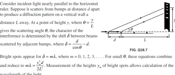
Q38.7 Consider incident light nearly parallel to the horizontal ruler. Suppose it scatters from bumps at distance d apart to produce a diffraction pattern on a vertical wall a
distance L away. At a point of height y, where θ = y L gives the scattering angle θ, the character of the interference is determined by the shift δ between beams scattered by adjacent bumps, where δ
θ = d −d
cos .
Bright spots appear for δ=mλ, where m = 0, 1, 2, 3, . . . . For small θ, these equations combine and reduce to m y d
L
m
λ = 22
2 . Measurement of the heights ym of bright spots allows calculation of the wavelength of the light.
*Q38.8 Answer (b). No diffraction effects are observed because the separation distance between adjacent ribs is so much greater than the wavelength of x-rays. Diffraction does not limit the resolution of an x-ray image. Diffraction might sometimes limit the resolution of an ultrasonogram.
*Q38.9 Answer (a). Glare, as usually encountered when driving or boating, is horizontally polarized. Refl ected light is polarized in the same plane as the refl ecting surface. As unpolarized light hits a shiny horizontal surface, the atoms on the surface absorb and then reemit the light energy as a refl ection. We can model the surface as containing conduction electrons free to vibrate eas-ily along the surface, but not to move easeas-ily out of surface. The light emitted from a vibrating electron is partially or completely polarized along the plane of vibration, thus horizontally.
Q38.10 Light from the sky is partially polarized. Light from the blue sky that is polarized at 90° to the polarization axis of the glasses will be blocked, making the sky look darker as compared to the clouds.
*Q38.11 Answer (a). The grooves in a diffraction grating are not electrically conducting. Sending light through a diffraction grating is not like sending a vibration on a rope through a picket fence. The electric fi eld in light does not have an amplitude in real space. Its amplitude is in newtons per coulomb, not in millimeters.
Q38.12 First think about the glass without a coin and about one particular point P on the screen. We can divide up the area of the glass into ring-shaped zones centered on the line joining P and the light source, with successive zones contributing alternately in-phase and out-of-phase with the light that takes the straight-line path to P. These Fresnel zones have nearly equal areas. An outer zone contributes only slightly less to the total wave disturbance at P than does the central circular zone. Now insert the coin. If P is in line with its center, the coin will block off the light from some particular number of zones. The fi rst unblocked zone around its circumference will send light to P with signifi cant amplitude. Zones farther out will predominantly interfere destructively with each other, and the Arago spot is bright. Slightly off the axis there is nearly complete destructive interference, so most of the geometrical shadow is dark. A bug on the screen crawling out past the edge of the geometrical shadow would in effect see the central few zones coming out of eclipse. As the light from them interferes alternately constructively and destructively, the bug moves through bright and dark fringes on the screen. The diffraction pattern is shown in Figure 38.3 in the text.
FIG. Q38.7 q
d L
y
ISMV2_5104_ch38.indd 380
Q38.13 Since the obsidian is opaque, a standard method of measuring incidence and refraction angles and using Snell’s Law is ineffective. Refl ect unpolarized light from the horizontal surface of the obsidian through a vertically polarized fi lter. Change the angle of incidence until you observe that none of the refl ected light is transmitted through the fi lter. This means that the refl ected light is completely horizontally polarized, and that the incidence and refl ection angles are the polarization angle. The tangent of the polarization angle is the index of refraction of the obsidian.
Q38.14 The fi ne hair blocks off light that would otherwise go through a fi ne slit and produce a diffraction pattern on a distant screen. The width of the central maximum in the pattern is inversely
proportional to the distance across the slit. When the hair is in place, it subtracts the same diffraction pattern from the projected disk of laser light. The hair produces a diffraction minimum that crosses the bright circle on the screen. The width of the minimum is inversely proportional to the diameter of the hair. The central minimum is fl anked by narrower maxima and minima. Measure the width 2y of the central minimum between the maxima bracketing it, and use
Equation 38.1 in the form y
L= λa to fi nd the width a of the hair.
Q38.15 The condition for constructive interference is that the three radio signals arrive at the city in phase. We know the speed of the waves (it is the speed of light c), the angular bearing θ of the city east of north from the broadcast site, and the distance d between adjacent towers. The wave from the westernmost tower must travel an extra distance 2dsinθ to reach the city, compared to the signal from the eastern tower. For each cycle of the carrier wave, the western antenna would
transmit fi rst, the center antenna after a time delay d c sinθ
, and the eastern antenna after an additional equal time delay.
Q38.16 It is shown in the correct orientation. If the horizontal width of the opening is equal to or less than the wavelength of the sound, then the equation asinθ=
( )
1 λ has the solution θ = °90 , or has no solution. The central diffraction maximum covers the whole seaward side. If the vertical height of the opening is large compared to the wavelength, then the angle in asinθ=( )
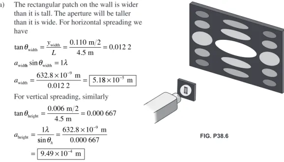
1 λ will be small, and the central diffraction maximum will form a thin horizontal sheet.Featured in the motion picture M*A*S*H (20th Century Fox, Aspen Productions, 1970) is a loudspeaker mounted on an exterior wall of an Army barracks. It has an approximately rectangular aperture, and it is installed incorrectly. The longer side is horizontal, to maximize sound spreading in a vertical plane and to minimize sound radiated in different horizontal directions.
SOLUTIONS TO PROBLEMS
Section 38.1 Introduction to Diffraction Patterns
Section 38.2 Diffraction Patterns from Narrow Slits
P38.1 sin .
. .
θ λ= = ×
× = ×
−
−
− a
6 328 10
3 00 10 2 11 10
7 4
3
y
1 00. m=tanθ≈sinθ θ≈ (for small θ) 2y= 4 22. mm
ISMV2_5104_ch38.indd 381
P38.2 The positions of the fi rst-order minima are y
L ≈sinθ= ±a
λ
. Thus, the spacing between these two
minima is ∆y
a L
= ⎛⎝⎜2 λ⎞⎠⎟ and the wavelength is λ = ⎛⎝ ⎞⎠⎛⎝ ⎞⎠ =⎛⎝⎜ ×
⎞ ⎠⎟
×
− −
∆y a L 2
4 10 103 0 550 10
. m .
2
3 3
547 m
2.06 m nm
⎛ ⎝⎜
⎞ ⎠⎟=
P38.3 y
L
m a
≈sinθ= λ ∆y=3 00 10. × −3 nm
∆m= − =3 1 2 and a m L y
= ∆ ∆
λ
a=
(
×)
(
)
×
(
)
= ×−
−
2 690 10 0 500
3 00 10 2 30
9 3
m m
m .
. . 110
4
− m
P38.4 For destructive interference,
sinθ=mλ λ= = . = .
a a
5 00
0 139 cm
36.0 cm
and θ =7 98. °
y L =tanθ
gives y=Ltanθ=
(
6 50. m)
tan .7 98°=0 912. m y= 91 2. cmP38.5 If the speed of sound is 340 m/s, λ = =v − =
f 340
650 1 0 523
m s
s . m
Diffraction minima occur at angles described by asinθ=mλ 1 10. m sin 1 1 0 523. m
(
)
θ =(
)
θ1=28 4. °1 10. m sin 2 2 0 523. m
(
)
θ =(
)
θ2 =72 0. °1 10. m sin 3 3 0 523. m
(
)
θ =(
)
θ3 nonexistentMaxima appear straight ahead at 0° and left and right at an angle given approximately by 1 10. m sin 1 5 0 523. . m
(
)
θx =(
)
θx ≈46°There is no solution to asinθ=2 5. λ, so our answer is already complete, with three sound maxima.
ISMV2_5104_ch38.indd 382
*P38.6 (a) The rectangular patch on the wall is wider than it is tall. The aperture will be taller than it is wide. For horizontal spreading we have tan . . . θwidth width widt m 2 m
= y = =
L a
0 110
4 5 0 012 2
h h width width m 0.012 2 sin . . θ = λ = × − = 1
632 8 10
5 1
9
a 88 10× −5 m
For vertical spreading, similarly
tan . . . θ λ height height m 2 m = = = 0 006
4 5 0 000 667
1 a ssin . . θh = × = × − − 632 8 10
9 49 10
9
4
m 0.000 667
m
(b) The central bright patch is horizontal. The aperture is vertical.
A smaller distance between aperture edges causes a wider diffraction angle. The longer dimension of each rectangle is 18.3 times larger than the smaller dimension.
P38.7 sinθ ≈ = . ×
− y
L
4 10 10 3 m 1.20 m
We defineφ π θ m
λ π = =
(
×)
× − −asin .
. 4 00 10 546 1 10
4 9 9
3
4 10 10
7 86 m
m
1.20 m rad
. . s max × ⎛ ⎝⎜ ⎞ ⎠⎟= = − I I
iin sin .
. . φ φ
(
)
⎡ ⎣ ⎢ ⎤⎦⎥ =⎡⎣⎢(
)
⎤⎦⎥ = × 2 2 7 867 86 1 62 10
−−2
P38.8 Equation 38.1 states that sinθ= mλ
a , where m= ± ±1, 2, ±3, . . . . The requirement for m=1 is from an analysis of the extra path distance traveled by ray 1 compared to ray 3 in the textbook
Figure 38.5. This extra distance must be equal to λ
2 for destructive interference. When the source rays approach the slit at an angle b, there is a distance added to the path difference (of ray 1 compared to ray 3) of a
2sinβ. Then, for destructive interference,
a a
2sinβ+ 2sinθ λ= 2 so sinθ λ= a0−sinβ.
Dividing the slit into 4 parts leads to the 2nd order minimum: sinθ= 2λ −sinβ a
Dividing the slit into 6 parts gives the third order minimum: sinθ= 3λ−sinβ a
Generalizing, we obtain the condition for the mth order minimum: sinθ= mλ −sinβ a
FIG. P38.6
FIG. P38.8
ISMV2_5104_ch38.indd 383
*P38.9 The diffraction envelope shows a broad central maximum fl anked by zeros at a sin θ = 1l and a sin θ = 2l. That is, the zeros are at (πa sin θ)/λ = π, −π, 2π, −2π, . . . . Not-ing that the distance between slits is d = 9µm = 3a, we say that within the diffraction envelope the interference pattern shows closely spaced maxima at d sin θ = mλ, giving (π 3a sin θ)/λ = mπ or (πa sin θ)/λ = 0, π/3, −π/3, 2π/3,
−2π/3. The third-order interference maxima are missing because they fall at the same directions as diffraction minima, but the fourth order can be visible at (πa sin θ)/λ = 4π/3 and –4π/3 as diagrammed.
P38.10 (a) Double-slit interference maxima are at angles given by dsinθ=mλ.
For m=0, θ0 = °0
For m=1,
(
2 80. µm)
sinθ=1 0 501 5(
. µm)
: θ1 10 179 10 3
= −
(
)
= °sin . .
Similarly, for m=2 3 4 5, , , and 6, θ2 = 21 0. ° , θ3= 32 5. ° , θ4 = 45 8. °
θ5= 63 6. ° , and θ6 1
1 07
= −
(
)
=sin . nonexistent
Thus, there are 5+ + =5 1 11directions for interference maxima.
(b) We check for missing orders by looking for single-slit diffraction minima, at asinθ=mλ. For m=1,
(
0 700. µm)
sinθ=1 0 501 5(
. µm)
and θ1=45 8. °Thus, there is no bright fringe at this angle. There are only nine bright fringes , at
θ = ° ±0, 10 3. ,° ±21 0. ,° ±32 5. ,° and ±63 6. °.
(c) I =I ⎡
(
a)
⎣
⎢ ⎤⎦⎥
max
sin sin
sin
π θ λ π θ λ
2
At θ = °0, sinθ
θ →1 and
I
Imax → 1 00.
At θ =10 3. °, π θ
λ
π µ
µ
asin . sin .
. .
=
(
0 700)
10 3° =0 501 5 0 785
m
m rrad=45 0. °
I Imax
sin .
. .
=⎡ °
⎣⎢ ⎤⎦⎥ =
45 0
0 785 0 811
2
Similarly, at θ =21 0. °, π θ
λ
asin
. .
=1 57rad=90 0°and I
Imax = 0 405.
At θ =32 5. °, π θ
λ
asin .
=2 36rad=135° and I
Imax = 0 090 1.
At θ =63 6. °, π θ
λ
asin .
=3 93rad=225° and I
Imax = 0 032 4.
−p p pasinq
l
0
I
FIG. P38.9
ISMV2_5104_ch38.indd 384
Section 38.3 Resolution of Single-Slit and Circular Apertures
P38.11 We assume Rayleigh’s criterion applies to the predator’s eye with pupil narrowed. (It is a few times too optimistic for a normal human eye with pupil dilated.)
sinθ λ= = . × .
× = ×
−
−
− a
5 00 10
1 00 10
7 4
3
m
5.00 10 rad
*P38.12 (a) 1 22. λ/D=1 22 589. ( nm)/(9 000 000nm) = 79 8. µrad
(b) For a smaller angle of diffraction we choose the smallest visible wavelength, violet at
400 nm, to obtain 1 22. λ/D=1 22 400. ( nm)/(9 000 000nm) = 54 2. µrad .
(c) The wavelength in water is shortened to its vacuum value divided by the index of refraction.
The resolving power is improved, with the miinimum resolvable angle becoming
1 22. λ/D=1 22 589. ( nm/ .1 33)/(9 000 000nm) = 60 0. µraad Better than water for many purposes is oil immersion.
P38.13 Undergoing diffraction from a circular opening, the beam spreads into a cone of half-angle
θmin . λ .
. .
= = ⎛ ×
⎝⎜
⎞ ⎠⎟=
−
1 22 1 22 632 8 10
0 005 00 1
9
D
m
m ..54 10
4
× − rad
The radius of the beam ten kilometers away is, from the defi nition of radian measure,
rbeam=θmin
(
1 00 10. × 4 m)
=1 544. mand its diameter is dbeam=2rbeam = 3 09. m .
*P38.14 When the pupil is open wide, it appears that the resolving power of human vision is limited by the coarseness of light sensors on the retina. But we use Rayleigh’s criterion as a handy indicator
of how good our vision might be. We take θmin = = . λ
d
L 1 22D, where θmin is the smallest angular separation of two objects for which they are resolved by an aperture of diameter D, d is the separation of the two objects, and L is the maximum distance of the aperture from the two objects at which they can be resolved.
Two objects can be resolved if their angular separation is greater thanθmin. Thus, θmin should be as small as possible. Therefore, light with the smaller of the two given wavelengths is easier to resolve, i.e., blue .
L= Dd =
(
×)
(
×)
=− −
1 22
5 20 10 2 80 10
1 22
1
3 2
.
. .
.
λ λ
m m ..193 10× −4 m2
λ
Thus L=186 m for λ =640 nm, and L=271 m for λ =440 nm. The viewer with the assumed diffraction-limited vision could resolve adjacent tubes of blue in the range 186 m to 271 m , but cannot resolve adjacent tubes of red in this range.
P38.15 When the pupil is open wide, it appears that the resolving power of human vision is limited by the coarseness of light sensors on the retina. But we use Rayleigh’s criterion as a handy indicator of how good our vision might be. According to this criterion, two dots separated center-to-center by 2.00 mm would overlap
when θmin = = . λ
d
L 1 22D
Thus, L= dD =
(
×)
(
×)
− −
1 22
2 00 10 4 00 10
1 22 500
3 3
.
. .
.
λ
m m
××
(
−)
=10 9 m 13 1. m
ISMV2_5104_ch38.indd 385
P38.16 When the pupil is open wide, it appears that the resolving power of human vision is limited by the coarseness of light sensors on the retina. But we use Rayleigh’s criterion as a handy indicator of how good our vision might be.
x
dD
= = ×
× ⎛ ⎝⎜
⎞ ⎠⎟
−
−
1 22 1 22 5 00 10 2
7 3
. λ . . m
5.00 10 m 550 10 30 5
3
×
(
m)
= . mP38.17 The concave mirror of the spy satellite is probably about 2 m in diameter, and is surely not more than 5 m in diameter. That is the size of the largest piece of glass successfully cast to a precise shape, for the mirror of the Hale telescope on Mount Palomar. If the spy satellite had a larger mir-ror, its manufacture could not be kept secret, and it would be visible from the ground. Outer space is probably closer than your state capitol, but the satellite is surely above 200-km altitude, for reasonably low air friction. We fi nd the distance between barely resolvable objects at a distance of 200 km, seen in yellow light through a 5-m aperture:
y
L D
y
=
=
(
)
(
)
⎛⎝⎜ × − ⎞⎠1 22
200 000 1 22 6 10
7
.
.
λ
m m
5 m ⎟⎟ =3 cm
(Considering atmospheric seeing caused by variations in air density and temperature, the distance
between barely resolvable objects is more like 200 000 1 1 3 600
m s
s
rad 180
(
)
( )
⎛⎝⎜ ° ⎞⎠⎟⎛⎝⎜π ° ⎠⎞⎟⎟ =97 cm.) Thus the snooping spy satellite cannot see the difference between III and II or IV on a license plate. It cannot count coins spilled on a sidewalk, much less read the dates on them.P38.18 1 22. λ D
d L
= λ = =c
f 0 020 0. m
D=2 10. m L=9 000 m d=1 22
(
0 020 0)(
9 000)
=2 10 105
. .
.
m m
m m
Section 38.4 The Diffraction Grating
P38.19 d= = × =
−
1 00 1 00 10
5 00
2
. .
. cm
2 000
m
2 000 µm
sin
. .
θ= λ =
(
×)
× =
−
− m
d
1 640 10
5 00 10 0 128
9 6
m
m θ = 7 35. °
D
d
= ×
= ×
= ×
−
− 250 10
5 00 10
5 00 10
3 7 3
m
m
m
λ . .
ISMV2_5104_ch38.indd 386
P38.20 The principal maxima are defi ned by
dsinθ=mλ m=0 1 2, , , . . . For m=1, λ=dsinθ
where q is the angle between the central (m=0) and the fi rst order (m=1) maxima. The value of q can be determined from the information given about the distance between maxima and the grating-to-screen distance. From the fi gure,
tanθ =0 488. m=0 284. 1.72 m
so θ =15 8. °
and sinθ =0 273.
The distance between grating “slits” equals the reciprocal of the number of grating lines per centimeter
d= 1 − = × − = ×
5 310 1 1 88 10 1 88 10
4 3
cm . cm . nm
The wavelength is λ=dsinθ=
(
1 88 10. × 3 nm)
(
0 273.)
= 514nmP38.21 The grating spacing is d= × = ×
−
− 1 00 10
2 22 10
2
6
.
. m
4 500 m
In the 1st-order spectrum, diffraction angles are given by
sinθ λ=
d: sinθ1 .
9 6
656 10
0 295
= ×
× =
−
− m
2.22 10 m
so that for red θ1 =17 17. °
and for blue sinθ2 .
9 6
434 10
10 0 195
= ×
× =
−
− m
2.22 m
so that θ2 =11 26. °
The angular separation is in fi rst-order, ∆θ =17 17. ° −11 26. ° = 5 91. °
In the second-order spectrum, ∆θ= ⎛ λ λ
⎝⎜ ⎞⎠⎟ − ⎛⎝⎜ ⎞⎠⎟ = °
− −
sin 1 2 1 sin 1 2 2 .
13 2
d d
Again, in the third order, ∆θ= ⎛ λ λ
⎝⎜ ⎞⎠⎟ − ⎛⎝⎜ ⎞⎠⎟ = °
− −
sin 1 3 1 sin 1 3 2 .
26 5
d d
Since the red does not appear in the fourth-order spectrum, the answer is complete.
FIG. P38.20
1.72 m
0.488 m q
FIG. P38.21
ISMV2_5104_ch38.indd 387
P38.22 sinθ =0 350. : d= λ = = ×
θ
sin
.
. 632 8
1 81 103
nm
0.350 nm
Line spacing = 1 81. µm
P38.23 (a) d= 1 = × − = × − =
3 660 2 732 10 2 732 10
4 6
lines cm . cm . m 22 732 nm
λ= d θ
m sin
: At θ =10 09. °, λ = 478 7. nm
At θ =13 71. °, λ = 647 6. nm
At θ =14 77. °, λ = 696 6. nm
(b) d= λ
θ
sin 1
and 2λ=dsinθ2 so sin
sin sin
θ λ λ
λ θ θ
2
1
1
2 2
2
= = =
d
Therefore, if θ1=10 09. ° then sinθ2 =2sin(10 09. °) gives θ2= 20 51. ° .
Similarly, for θ1=13 71. °,θ2 = 28 30. ° and for θ1=14 77. °, θ2 = 30 66. ° .
P38.24 sinθ= mλ
d
Therefore, taking the ends of the visible spectrum to be λv =400 nm and λr =750 nm, the ends of the different order spectra are defi ned by:
End of second order: sinθ2r 2λr 1 500
d d
= = nm
Start of third order: sinθ3v =3λv =1 200
d d
nm
Thus, it is seen that θ2r >θ3v and these orders must overlap regardless of the value of the grating spacing d.
*P38.25 The sound has wavelength λ = =
× = ×
− v
f
343
37 2 103 9 22 10
3
m s
s m
. . . Each diffracted beam is described
by dsinθ=mλ, m=0 1 2, , , . . .
The zero-order beam is at m=0, θ =0. The beams in the fi rst order of interference are to the left and right at θ= λ= ×
× =
− − −
−
−
sin sin .
. sin
1 1
3 2
1
1 9 22 10
1 3 10 d
m
m 00 709. =45 2. °. For a second-order beam we would need θ=sin−12λ =sin−1
(
.)
=sin−1 .2 0 709 1 42
d . No angle, smaller or larger than 90°,
has a sine greater than 1. Then a diffracted beam does not exist for the second order or any higher
order. The whole answer is then, three beams, at 0° and at 45.2° to the rightand to the left .
ISMV2_5104_ch38.indd 388
P38.26 For a side maximum, tanθ . µ
µ = y =
L
0 4 m
6.9 m
θ =3 32. °
dsinθ=mλ d=
( )
(
×)
° =
− 1 780 10
3 32 13 5
9
m
m
sin . . µ
The number of grooves per millimeter = ×
× =
−
− 1 10
74 2
3
m 13.5 10 6 m
.
P38.27 d= × = × =
−
− 1 00 10
250 4 00 10 4 000
3
6
.
. m mm
lines mm m nm d m m
d
sinθ λ sinθ
λ
= ⇒ =
(a) The number of times a complete order is seen is the same as the number of orders in which the long wavelength limit is visible.
mmax d max
sin sin .
.
= θ =
(
)
°=λ
4 000 90 0
700 5 71
nm nm
or 5 orders is the maximum
(b) The highest order in which the violet end of the spectrum can be seen is:
mmax=dsinθmax =
(
)
sin . °= .λ
4 000 90 0
400 10 0
nm nm
or 10 orders in the short-wavelength region
P38.28 (a) The several narrow parallel slits make a diffraction grating. The zeroth- and fi rst-order maxima are separated according to
dsinθ=
( )
1λ sinθ λ= = . ××
−
− d
632 8 10 9
3
m 1.2 10 m
θ =sin−1
(
.)
= .0 000 527 0 000 527 rad
y=Ltanθ=
(
1 40. m)
(
0 000 527.)
= 0 738. mm (b) Many equally spaced transparent lines appear on thefi lm. It is itself a diffraction grating. When the same light is sent through the fi lm, it produces interference maxima separated according to
dsinθ=
( )
1 λ sinθ λ= = . × .× =
−
− d
632 8 10
0 000 857
9 3
m
0.738 10 m
y=Ltanθ=
(
1 40. m)
(
0 000 857.)
=1 20. mmAn image of the original set of slits appears on the screen. If the screen is removed, light diverges from the real images with the same wave fronts reconstructed as the original slits produced. Reasoning from the mathematics of Fourier transforms, Gabor showed that light diverging from any object, not just a set of slits, could be used. In the picture, the slits or maxima on the left are separated by 1.20 mm. The slits or maxima on the right are separated by 0.738 mm. The length difference between any pair of lines is an integer number of wavelengths. Light can be sent through equally well toward the right or toward the left. Soccer players shift smoothly between offensive and defensive tactics.
FIG. P38.26
FIG. P38.28
ISMV2_5104_ch38.indd 389
P38.29 d= 1 = × − =
4 200 2 38 10 2 380
6
cm . m nm
dsinθ=mλ or θ= ⎛ λ
⎝⎜ ⎞⎠⎟
− sin 1 m
d and y L L
m d = = ⎡ ⎛⎝⎜ ⎞⎠⎟ ⎣⎢ ⎤ ⎦⎥ −
tanθ tan sin 1 λ
Thus, ∆y L m
d m d = ⎡ ⎛⎝⎜ ⎞⎠⎟ ⎣⎢ ⎤ ⎦⎥− ⎛ ⎝ − −
tan sin1 λ2 tan sin1 λ1
⎜⎜ ⎞⎠⎟ ⎡ ⎣⎢ ⎤ ⎦⎥ ⎧ ⎨ ⎩ ⎫ ⎬ ⎭
For m=1, ∆y=
(
)
⎛⎝⎜ ⎞ ⎠⎟ ⎡ ⎣ ⎢ ⎤ ⎦ ⎥ − −
2 00 589 6
2 380
1
. m tan sin . tann sin− ⎛ .
⎝⎜ ⎞ ⎠⎟ ⎡ ⎣ ⎢ ⎤ ⎦ ⎥ ⎧ ⎨ ⎪ ⎩⎪ ⎫ ⎬ ⎪ ⎭⎪= 1 589
2 380 0 554 mmm
For m=2, ∆y=
(
)
⎛(
)
⎝⎜ ⎞ ⎠⎟ ⎡ ⎣ ⎢ ⎤ ⎦ ⎥ −
2 00 2 589 6
2 380
1
. m tan sin . −− ⎛
(
)
⎝⎜ ⎞ ⎠⎟ ⎡ ⎣ ⎢ ⎤ ⎦ ⎥ ⎧ ⎨ ⎪ ⎩⎪ ⎫ ⎬ ⎪ ⎭⎪= −
tan sin 1 2 589
2 380 11 54. mm
For m=3, ∆y=
(
)
⎛(
)
⎝⎜ ⎞ ⎠⎟ ⎡ ⎣ ⎢ ⎤ ⎦ ⎥ −
2 00 3 589 6
2 380
1
. m tan sin . −− ⎛
(
)
⎝⎜ ⎞ ⎠⎟ ⎡ ⎣ ⎢ ⎤ ⎦ ⎥ ⎧ ⎨ ⎪ ⎩⎪ ⎫ ⎬ ⎪ ⎭⎪= −
tan sin1 3 589
2 380 55 04. mm
Thus, the observed order must be m=2 .
Section 38.5 Diffraction of X-Rays by Crystals
P38.30 2dsinθ=mλ: λ= θ =
(
×)
° = ×−
−
2 2 0 353 10 7 60
1 9 34 10
9
1
d m
sin . sin .
.
m 11
0 093 4
m= . nm
P38.31 2dsinθ=mλ: sin .
. . θ= λ =
(
×)
×(
)
= − − m d 21 0 140 10
2 0 281 10 0
9 9
m
m 2249
and θ =14 4. °
P38.32 Figure 38.23 of the text shows the situation.
2dsinθ=mλ or λ=2d θ m sin
m=1: λ1
2 2 80 80 0
1 5 51
=
(
. m)
sin . ° = . mm=2: λ2
2 2 80 80 0
2 2 76
=
(
. m)
sin . ° = . mm=3: λ3 2 2 80 80 0
3 1 84
=
(
. m)
sin . ° = . m*P38.33 The crystal cannot produce diffracted beams of visible light. The wavelengths of visible light are some hundreds of nanometers. There is no angle whose sine is greater than 1. Bragg’s law 2d sin q = ml cannot be satisfi ed for a wavelength much larger than the distance between atomic planes in the crystal.
ISMV2_5104_ch38.indd 390
Section 38.6 Polarization of Light Waves
P38.34 The average value of the cosine-squared function is one-half, so the fi rst polarizer transmits
1
2 the light. The second transmits cos .
2
30 0 3
4
° = .
If = × Ii = Ii 1
2 3 4
3 8
P38.35 I=Imaxcos 2
θ ⇒ θ = −
cos
max
1 I
I
(a) I
Imax .
= 1
3 00 ⇒ θ = = °
− cos
. .
1 1
3 00 54 7
(b) I
Imax .
= 1
5 00 ⇒ θ = = °
− cos
. .
1 1
5 00 63 4
(c) I
Imax = . 1
10 0 ⇒ θ = = °
− cos
. .
1 1
10 0 71 6
P38.36 By Brewster’s law, n=tanθp =tan
(
48 0. °)
= 1 11.P38.37 sinθc
n
=1 or n
c
= =
°=
1 1
34 4 1 77
sinθ sin . .
Also, tanθp =n. Thus, θp =
( )
n =(
)
= °− −
tan 1 tan1 . .
1 77 60 5
P38.38 sinθc
n
= 1 and tanθp=n
Thus, sin
tan
θ
θ
c
p
= 1 or cotθp=sinθc .
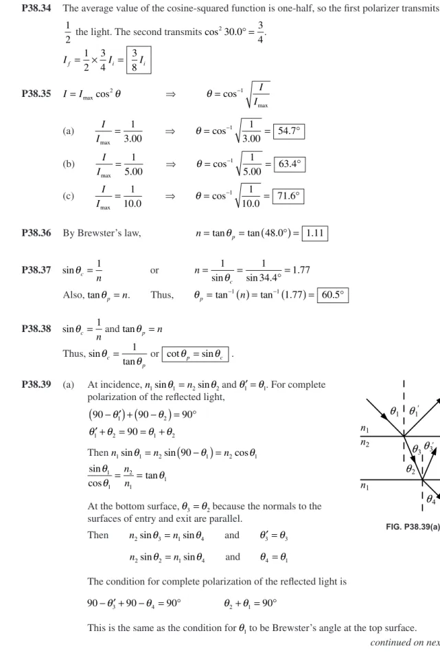
P38.39 (a) At incidence, n1sinθ1=n2sinθ2 and θ1′ =θ1. For complete
polarization of the refl ected light,
90 90 90
90
1 2
1 2 1 2
− ′
(
)
+(
−)
= ° ′ + = = +θ θ
θ θ θ θ
Then n1sinθ1=n2sin
(
90−θ1)
=n2cosθ1sin
cos tan
θ
θ θ
1 1
2 1
1
=n =
n
At the bottom surface, θ3=θ2 because the normals to the
surfaces of entry and exit are parallel.
Then n2sinθ3=n1sinθ4 and θ3′ =θ3
n2sinθ2=n1sinθ4 and θ4 =θ1
The condition for complete polarization of the refl ected light is
90− ′ +θ3 90−θ4 = °90 θ θ2+ = °1 90
This is the same as the condition for θ1 to be Brewster’s angle at the top surface.
continued on next page FIG. P38.39(a)
n1
n2
q1 q1'
n1
q3q3
'
q2
q4
ISMV2_5104_ch38.indd 391
(b) We consider light moving in a plane perpendicular to the line where the surfaces of the prism meet at the unknown angle Φ. We require
n1 1 n2 2
1 2 90
sinθ sinθ
θ θ = + = °
So n1sin
(
90−θ2)
=n2sinθ2n n
1 2
2
=tanθ
And n2sinθ3=n3sinθ4 θ θ3+ 4 = °90
n2sinθ3=n3cosθ3 tanθ3 3 2
= n
n
In the triangle made by the faces of the prism and the ray in the prism,
Φ +90+ +θ2
(
90−θ3)
=180So one particular apex angle is required, annd it is
Φ = − = ⎛
⎝⎜ ⎞ ⎠⎟−
⎛ ⎝⎜
⎞ ⎠⎟
− −
θ θ3 2
1 3
2
1 1
2
tan n tan
n
n n
Here a negative result is to be interpreted as meaning the same as a positive result.
P38.40 For incident unpolarized light of intensity Imax:
The average value of the cosine-squared function is one half, so the intensity after transmission by the fi rst disk is
I=1I 2 max
After transmitting 2nd disk: I =1I 2
2 maxcos θ
After transmitting 3rd disk: I=1I
(
° −)
2 90
2 2
maxcos θcos θ
where the angle between the fi rst and second disk is θ ω= t. Using trigonometric identities cos2 1 cos
2 1 2
θ=
(
+ θ)
and cos2 sin2 cos
90 1
2 1 2
° −
(
θ)
= θ=(
− θ)
we have I= I ⎡
(
+)
⎣⎢
⎤ ⎦⎥
−
(
)
⎡ ⎣⎢
⎤ ⎦⎥
1 2
1 2
2
1 2
2
max
cos θ cos θ
I= I
(
−)
= I ⎛⎝ ⎞⎠ −
(
)
1
8 1 2
1 8
1
2 1 4
2
max cos θ max cos θ
Sinceθ ω= t, the intensity of the emerging beam is given by I= 1 I
(
− t)
16 max 1 4ω .FIG. P38.39(b)
q1 q1
q2
q3q 3
q4
Φ
n1 n2
n3
FIG. P38.40
ISMV2_5104_ch38.indd 392
*P38.41 (a) Let I0 represent the intensity of unpolarized light incident on the fi rst polarizer. In Malus’s law the average value of the cosine-squared function is 1/2, so the fi rst fi lter lets through 1/2 of the incident intensity. Of the light reaching them, the second fi lter passes cos245° = 1/2 and
the third fi lter also cos245° = 1/2. The transmitted intensity is then I
0(1/2)(1/2)(1/2) = 0.125 I0.
The reduction in intensity is by a factor of 0.875 of the incident intensity.
(b) By the same logic as in part (a) we have transmitted I0(1/2)(cos230°)(cos230°)(cos230°) =
I0(1/2)(cos230°)3 = 0.211 I
0. Then the fraction absorbed is 0.789 .
(c) Yet again we compute transmission I0(1/2)(cos215°)6 = 0.330 I
0. And the fraction absorbed
is 0.670 .
(d) We can get more and more of the incident light through the stack of ideal fi lters, approach-ing 50%, by reducapproach-ing the angle between the transmission axes of each one and the next.
Additional Problems
*P38.42 The central bright fringe is wider than the side bright fringes, so the light must have been diffracted by a single slit . For precision, we measure from the second minimum on one side of the center to the second minimum on the other side:
2y=(11 7. −6 3. )cm =5 4. cm y=22 7 0 027
2 6 0 010 4
0 595
.
tan .
. .
.
cm m
m
θ θ
= = =
= °
y L
== =
= = ×
− 0 010 4
2 632 8 109 .
sin
sin
. rad
m
a m
a m
θ λ
λ
θ
((
°)
=×
(
−)
= ×sin .
.
. .
0 595
2 632 8 10
0 010 4 1 22 10
9
m −−4
m
P38.43 Let the fi rst sheet have its axis at angle q to the original plane of polarization, and let each further sheet have its axis turned by the same angle.
The fi rst sheet passes intensity Imaxcos 2
θ
The second sheet passes Imaxcos 4
θ
and the nth sheet lets through Imaxcosn . Imax 2
0 90
θ ≥ where θ =45° n
Try different integers to fi nd cos2 5 45 .
5 0 885
× ⎛ °
⎝⎜ ⎞⎠⎟ = cos2 6 .
45
6 0 902
× ⎛ °
⎝⎜ ⎞⎠⎟ =
(a) So n= 6 (b) θ = 7 50. °
ISMV2_5104_ch38.indd 393
P38.44 Consider vocal sound moving at 340 m/s and of frequency 3 000 Hz. Its wavelength is
λ = =v = f
340
3 000 0 113
m s
Hz . m
If your mouth, for horizontal dispersion, behaves similarly to a slit 6.00 cm wide, then asinθ=mλ predicts no diffraction minima. You are a nearly isotropic source of this sound. It spreads out from you nearly equally in all directions. On the other hand, if you use a megaphone with width 60.0 cm at its wide end, then asinθ=mλ predicts the fi rst diffraction minimum at
θ= ⎛ λ
⎝⎜ ⎞⎠⎟ = ⎛⎝⎜ ⎞⎠⎟ =
− −
sin 1 m sin 1 0 113.
a
m
0.600 m 110 9. °
This suggests that the sound is radiated mostly toward the front into a diverging beam of angular diameter only about 20°. With less sound energy wasted in other directions, more is available for your intended auditors. We could check that a distant observer to the side or behind you receives less sound when a megaphone is used.
*P38.45 (a) We assume the fi rst side maximum is at a sinq = 1.5 l. (Its location is determined more precisely in problem 66.) Then the required fractional intensity is
I I
a a
max
sin( sin / ) sin /
sin( .
= ⎡ ⎣
⎢ ππ θ λθ λ ⎤⎦⎥ = π
2
1 5 ))
. . .
1 5
1
2 25 0 0450
2
2
π π
⎡
⎣⎢ ⎤⎦⎥ = =
(b) Proceeding as in part (a) we have a sinq/l = 2.5 and
I I
a a
max
sin( sin / ) sin /
sin( .
= ⎡ ⎣
⎢ ππ θ λθ λ ⎤⎦⎥ = π
2
2 5 ))
. . .
2 5
1
6 25 0 0162
2
2
π π
⎡
⎣⎢ ⎤⎦⎥ = =
*P38.46 The energy in the central maximum we can estimate in Figure 38.6 as proportional to
(height)(width) = Imax(2p)
As in problem 45, the maximum height of the fi rst side maximum is approximately
Imax[sin (3p /2)/(3p /2)]2 = 4I max/9p
2
Then the energy in one side maximum is proportional to p (4Imax/9p2),
and that in both of the fi rst side maxima together is proportional to 2p (4Imax/9p2).
Similarly and more precisely, and always with the same proportionality constant, the energy in both of the second side maxima is proportional to 2p (4Imax/25p2).
The energy in all of the side maxima together is proportional to
2p (4Imax/p2)[1/32 + 1/52 + 1/72 + …] = 2p (4I max/p
2)[p2/8 – 1] = (8I max/p )[p
2/8 – 1]
= Imax(p – 8/p) = 0.595Imax
The ratio of the energy in the central maximum to the total energy is then
Imax(2p)/{Imax(2p) + 0.595Imax} = 2p /6.88 = 0.913 = 91.3%
Our calculation is only a rough estimate, because the shape of the central maximum in particular is not just a vertically-stretched cycle of a cosine curve. It is slimmer than that.
ISMV2_5104_ch38.indd 394
P38.47 The fi rst minimum is at asinθ=
( )
1 λ This has no solution if λa>1
or if a< =λ 632 8. nm
*P38.48 With light in effect moving through vacuum, Rayleigh’s criterion limits the resolution according to
d/L = 1.22 l/D D = 1.22 lL/d = 1.22 (885 × 10–9 m) 12 000 m/2.3 m = 5.63 mm
The assumption is absurd. Over a horizontal path of 12 km in air, density variations associated with convection (“heat waves” or what an astronomer calls “seeing”) would make the motor-cycles completely unresolvable with any optical device.
P38.49 d= 1 − = × −
400 1 2 50 10
6
mm . m
(a) dsinθ=mλ θa =
× ×
× ⎛ ⎝⎜
⎞
⎠⎟= °
− −
−
sin1 .
9 6
2 541 10
25 6 m
2.50 10 m
(b) λ = × = ×
−
− 541 10
4 07 10
9
7
m
1.33 . m θb =
× ×
× ⎛
⎝⎜ ⎞⎠⎟=
− −
−
sin 1 . .
7 6
2 4 07 10
19 0 m
2.50 10 m °°
(c) dsinθa =2λ and d
n
b sinθ =2λ
combine by substitution to give nsinθb =
( )
1sinθaP38.50 (a) λ = v
f: λ =
×
× − =
3 00 10
1 40 10 0 214
8
9 1
.
. .
m s
s m
θmin =1 22. λ
D: θmin . µ
.
.
=
× ⎛
⎝ ⎞⎠ =
1 22 0 214m 7 26
3.60 10 m4 rad
θ µ
π
min = . .
× × ⎛
⎝ ⎞⎠ =
7 26 rad 180 60 60s 1 50arc secoonds
(b) θmin = d
L: d= L=
(
×)
(
)
=−
θmin 7 26 10. 26 000 0 189.
6
rad ly ly
(c) It is not true for humans, but we assume the hawk’s visual acuity is limited only by Rayleigh’s criterion.
θmin =1 22. λ
D θmin = . . µ
× × ⎛ ⎝⎜
⎞ ⎠⎟=
−
−
1 22 500 10 50 8
9 3
m
12.0 10 m rrad
(
10 5. seconds of arc)
(d) d=θminL=
(
50 8 10. × −6)
(
30 0.)
=1 52 10. × −3rad m m== 1 52. mm
ISMV2_5104_ch38.indd 395
P38.51 With a grazing angle of 36.0°, the angle of incidence is 54.0°
tanθp = =n tan54 0. ° =1 38. In the liquid, λn λ
n
= =750nm= 545
1.38 nm .
P38.52 (a) Bragg’s law applies to the space lattice of melanin rods. Consider the planes d=0 25. µm apart. For light at near-normal incidence, strong refl ection happens for the wavelength given by 2dsinθ=mλ. The longest wavelength refl ected strongly corresponds to m=1:
2 0 25 106 90 1
. × sin
(
− m)
° = λ λ =500 nm. This is the blue-green color.(b) For light incident at grazing angle 60°, 2dsinθ=mλ gives 1λ =2 0 25 10
(
. × −6 m)
sin60° =433nm. This is violet.(c) Your two eyes receive light refl ected from the feather at different angles, so they receive light incident at different angles and containing different colors reinforced by constructive interference.
(d) The longest wavelength that can be refl ected with extra strength by these melanin rods is the one we computed fi rst, 500 nm blue-green.
(e) If the melanin rods were farther apart (say 0 32. µm) they could refl ect red with constructive interference.
P38.53 (a) dsinθ=mλ
or d= m =
(
×)
° =
−
λ
θ µ
sin sin . .
3 500 10
32 0 2 83
9
m
m
Therefore, lines per unit length = =
× −
1 1
2 83 10 6
d . m
or lines per unit length =3 53 10× 5 −1 = 3 53 10× 3 −1
. m . cm .
(b) sin
. .
θ= λ =
(
×)
× =
(
)
−
− m
d m
m 500 10
2 83 10 0 177
9 6
m m
For sinθ ≤1 00. , we must have m
(
0 177.)
≤1 00.or m≤5 66.
Therefore, the highest order observed is m=5 Total number of primary maxima observed is 2m+ =1 11
ISMV2_5104_ch38.indd 396
*P38.54 (a) For the air-to-water interface,
tan .
.
θp
n n
= water =
air
1 33
1 00 θp =53 1. ° and
(
1 00.)
sinθp =(
1 33.)
sinθ2θ2
1 53 1
1 33 36 9
= − ⎛⎝ ° ⎞⎠ = °
sin sin .
. .
For the water-to-slab interface, tan tan
.
θp θ
n n
n
= 3= =
1 33
slab water
so θ3 1
1 33
=tan ( / .− n ).
The angle between surfaces is θ θ θ= 3− 2 = tan−
1(n /1.33) − 36.9°.
(b) If we imagine n→
∞
, then θ→ 53.1°. The material of the slab in this case is higher in opti-cal density than any gem. The light in the water skims along the upper surface of the slab.(c) If we imagine n = 1, then θ = 0. The slab is so low in optical density that it is like air. The light strikes parallel surfaces as it enters and exits the water, both at the polarizing angle.
P38.55 A central maximum and side maxima in seven orders of interference appear. If the seventh order is just at 90°,
dsinθ=mλ d
( )
1 =7 654 10(
× −9 m)
d=4 58. µmIf the seventh order is at less than 90°, the eighth order might be nearly ready to appear according to
d
( )
1 8 654 109=
(
× − m)
d=5 23. µm Thus 4 58. µm< <d 5 23. µm .
P38.56 (a) We require θmin =1 22. λ = =
2
D L
D L radius of diffraction disk
Then D2 =2 44. λL
(b) D= 2 44 500 10
(
× −9)
(
0 150)
= 428. m . m µm
P38.57 For the limiting angle of resolution between lines we
assume θmin . λ .
.
= =
(
×)
×
(
)
=−
−
1 22 1 22 550 10
5 00 10 1
9 3
D
m
m ..34 10
4
× − rad.
Assuming a picture screen with vertical dimension , the minimum viewing distance for no
visible lines is found from θmin=
485
L . The desired ratio is then L
= =
(
× −)
=1 485
1
485 1 34 10 4 15 4
θmin .
. rad
When the pupil of a human eye is wide open, its actual resolving power is signifi cantly poorer than Rayleigh’s criterion suggests.
FIG. P38.55 FIG. P38.54
Air Water q3
q2
qp
q
ISMV2_5104_ch38.indd 397
P38.58 (a) Applying Snell’s law gives n2sinφ=n1sinθ. From the sketch,
we also see that:
θ φ β π+ + = , or φ π= − +
(
θ β)
Using the given identity:sinφ=sinπcos
(
θ β+)
−cos sinπ(
θ β+)
which reduces to: sinφ=sin
(
θ β+)
Applying the identity again: sinφ=sin cosθ β+cos sinθ β Snell’s law then becomes: n2
(
sin cosθ β+cos sinθ β)
=n1sinθor (after dividing by cosq): n2
(
tan cosθ β+sinβ)
=n1tanθSolving for tanθ gives: tan sin
cos
θ β
β =
−
n
n n
2
1 2
(b) If β =90 0. °, n1=1 00. , and n2 =n, the above result becomes:
tan .
.
θ =
(
)
−n1 00
1 00 0, or n=tanθ, which is Brewster’s law.
P38.59 (a) From Equation 38.1, θ= ⎛ λ
⎝⎜ ⎞⎠⎟
− sin 1 m
a
In this case m=1 and λ = = ×
× = ×
− c
f
3 00 10
7 50 10 4 00 10
8 9
2
.
. .
m s
Hz m
Thus, θ = ×
× ⎛
⎝⎜ ⎞⎠⎟= °
− −
−
sin .
. .
1
2 2
4 00 10
6 00 10 41 8
m m
(b) From Equation 38.2, I Imax
sin
=⎡
(
)
⎣⎢ ⎤
⎦ ⎥ φ φ
2
where φ π θ
λ = asin
When θ =15 0. °, φ=π
(
0 060 0)
15 0° =0 040 0 1 22
. sin .
. .
m
m rad
and I
Imax
sin .
. .
=⎡
(
)
⎣⎢
⎤ ⎦⎥ =
1 22
1 22 0 593
2
rad rad
(c) sinθ λ=
a so θ =41 8. °:
This is the minimum angle subtended by the two sources at the slit. Let
a be the half angle between the sources, each a distance =0 100. m from the center line and a distance L from the slit plane. Then,
L= =
(
)
⎛ °⎝ ⎞⎠ =
cotα 0 100. cot 41 8. .
2 0 262
m m FIG. P38.59(c)
FIG. P38.58(a)
ISMV2_5104_ch38.indd 398
*P38.60 (a) The fi rst sheet transmits one-half the intensity of the originally unpolarized light, because the average value of the cosine-squared function in Malus’s law is one-half. Then
I Imax
cos . cos .
=1
(
°)
(
°)
=2 45 0 45 0
1 8
2 2
(b) No recipes remain. The two experiments follow precisely analogous steps, but the results are different. The middle fi lter in part (a) changes the polarization state of the light that passes through it, but the recipe selections do not change individual recipes. The result for light gives us a glimpse of how quantum-mechanical measurements differ from classical measurements.
P38.61 (a) Constructive interference of light of wavelength l on the screen is described by
dsinθ=mλ where tanθ = y
L so sinθ = + y
L2 y2. Then
( )
d y L(
+y)
=m−
2 2 1 2 λ
.
Differentiating with respect to y gives
d1 L y d y 1 L y y md
2 0 2
2+ 2 1 2 2 2 3 2
(
)
− +( )
⎛⎝− ⎞⎠(
+)
−(
+)
= λλ λ dy d L y d yL y m
d dy
d L d
2 2 1 2
2 2 2 3 2
2 +
(
)
−(
( )
+)
= =( )
+(( )
−( )
+(
)
=( )
+(
)
y d y
L y
d dy
d L
m L y
2 2
2 2 3 2 2
2 2 3 2
λ
(b) Here dsinθ=mλ gives 10
8 000 1 550 10
2 9 − − =
(
×)
m msinθ , θ = ×
× ⎛ ⎝⎜ ⎞ ⎠⎟= ° − − −
sin 1 . .
6 6
0 55 10
10 26 1
m
1.25 m
y=Ltanθ=2 40. mtan26 1. ° =1 18. m
Now d
dy
dL
m L y
λ = +
(
)
= ×(
)
−
2 2 2 3 2
6 2
1 25 10
1 2 4 .
.
m 2.40 m
m m
nm cm
(
)
+(
)
(
2 2 3 2)
= × − =7
1 18
3 77 10 3 77
.
. . .
P38.62 (a) The angles of bright beams diffracted from the grating are given by
( )
d sinθ=mλ. The angular dispersion is defi ned as the derivative dd
θ
λ: d
d
d m
( )
cosθ θ = λ d d m d θλ = cosθ
(b) For the average wavelength 578 nm,
dsinθ=mλ 0 02. msin 2 578 10 9
8 000 θ =
(
× m)
−
θ = × ×
× = °
− −
−
sin 1 .
9 6
2 578 10
27 5 m
2.5 10 m
The separation angle between the lines is
∆θ θ∆ ∆ λ λ θ λ = = = × − ° × d d m
dcos . cos . .
2
2 5 106 27 5 2 11
m 110
0 001 90 0 001 90 0 001 90 180
9 − = = = m rad rad . . . ⎛ °°
⎝π rad⎞⎠ = 0 109. °
ISMV2_5104_ch38.indd 399
P38.63 (a) The E and O rays, in phase at the surface of the plate, will have a phase difference
θ π
λ δ = ⎛⎝2 ⎞⎠
after traveling distance d through the plate. Here d is the difference in the optical path
lengths of these rays. The optical path length between two points is the product of the actual path length d and the index of refraction. Therefore,
δ = dnO−dnE
The absolute value is used since n n
O
E
may be more or less than unity. Therefore,
θ π
λ
π λ
= ⎛⎝2 ⎠⎞ dnO−dnE = ⎛⎝2 ⎠⎞d nO−nE
(b) d
nO nE
=
− =
×
(
)
(
)
− =
−
λθ π
π π
2
550 10 2
2 1 544 1 553 1
9
m
. . ..53 10 15 3.
5
× − =
m µm
P38.64 (a) From Equation 38.2, I
Imax
sin
=⎡
(
)
⎣⎢ ⎤
⎦ ⎥ φ φ
2
where we defi ne φ π θ
λ ≡ asin
Therefore, when I
Imax
=1
2 we must have sinφ
φ =
1
2, or sinφ
φ =
2
(b) Let y1=sinφ and y2
2
= φ .
A plot of y1 and y2 in the range 1 00
2
. ≤ ≤φ π is shown to
the right.
The solution to the transcendental equation is found to
be φ =1 39. rad .
(c) π θ
λ φ
asin
= gives sinθ φ .
π
λ λ
= ⎛⎝ ⎞⎠ =a 0 443a.
If λ
a is small, then θ
λ ≈0 443.
a.
This gives the half-width, measured away from the maximum at θ =0. The pattern is symmetric, so the full width is given by
∆θ=0 443. λ − −⎛⎝⎜ 0 443. λ⎞⎠⎟ = 0 886. λ
a a a
FIG. P38.64(b)
ISMV2_5104_ch38.indd 400
P38.65 f 2 sinφ
1 1.19 bigger than f
2 1.29 smaller than f
1.5 1.41 smaller
1.4 1.394
1.39 1.391 bigger
1.395 1.392
1.392 1.391 7 smaller
1.391 5 1.391 54 bigger
1.391 52 1.391 55 bigger
1.391 6 1.391 568 smaller
1.391 58 1.391 563
1.391 57 1.391 561
1.391 56 1.391 558
1.391 559 1.391 557 8
1.391 558 1.391 557 5
1.391 557 1.391 557 3
1.391 557 4 1.391 557 4
We get the answer as 1.391 557 4 to seven digits after 17 steps. Clever guessing, like using the value of 2 sinφ as the next guess for f, could reduce this to around 13 steps.
P38.66 In I=I ⎡
(
)
⎣ ⎢ ⎤⎦⎥
max
sin φ
φ
2
we fi nd dI dφ I
φ φ
φ φ φ
φ
= ⎛
(
)
⎝⎜
⎞
⎠⎟
(
)
(
)
−
(
)
(
)
max
sin cos sin
2
2
⎡⎡ ⎣ ⎢ ⎢
⎤ ⎦ ⎥ ⎥
and require that it be zero. The possibility sin
(
φ)
=0 locates all of the minima and the central maximum, according toφ=0,π π, 2 , . . .; φ π θ
λ π π
= asin =0, , 2 , . . .; asinθ=0, λ λ, 2 , . . .
The side maxima are found from φcos
(
φ)
−sin(
φ)
=0, or tan(
φ)
=φThis has solutions φ =4 493 4. , φ =7 725 3. , and others, giving (a) πasinθ=4 493 4. λ asinθ=1 430 3. λ
(b) πasinθ=7 725 3. λ asinθ=2 459 0. λ
ISMV2_5104_ch38.indd 401
P38.67 The fi rst minimum in the single-slit diffraction pattern occurs at
sinθ λ= ≈ min
a y
L
Thus, the slit width is given by
a L
y
= λ
min
For a minimum located at ymin =6 36. mm±0 08. mm, the width is
a=
(
×)
(
)
× =
−
−
632 8 10 1 00
6 36 10 99 5
9 3
. .
. .
m m
m µ ±±m 1%
ANSWERS TO EVEN PROBLEMS
P38.2 547 nm
P38.4 91 2. cm
P38.6 (a) 51.8 mm wide and 949 mm high (b) horizontal; vertical. See the solution. A smaller distance between aperture edges causes a wider diffraction angle. The longer dimension of each rectangle is 18.3 times larger than the smaller dimension.
P38.8 See the solution.
P38.10 (a) 0°, 10 3. °, 21 0. °, 32 5. °, 45 8. °, 63 6. ° (b) nine bright fringes, at 0° and on either side at 10 3. °, 21 0. °, 32 5. °, and 63 6. ° (c) 1 00. , 0 811. , 0 405. , 0 090 1. , 0 032 4.
P38.12 (a) 79.8 mrad (b) violet, 54.2 mrad (c) The resolving power is improved, with the minimum resolvable angle becoming 60.0 mrad.
P38.14 Between 186 m and 271 m; blue is resolvable at larger distances because it has shorter wavelength.
P38.16 30 5. m
P38.18 105 m
P38.20 514 nm
P38.22 1 81. µm P38.24 See the solution.
P38.26 74.2 grooves/mm
P38.28 (a) 0 738. mm (b) See the solution.
P38.30 93.4 pm
P38.32 5.51 m, 2.76 m, 1.84 m
FIG. P38.67
ISMV2_5104_ch38.indd 402
P38.34 3 8
P38.36 1.11
P38.38 See the solution.
P38.40 See the solution.
P38.42 One slit 0.122 mm wide. The central maximum is twice as wide as the other maxima.
P38.44 See the solution.
P38.46 See the solution.
P38.48 5.63 mm. The assumption is absurd. Over a horizontal path of 12 km in air, density variations associated with convection (“heat waves” or what an astronomer calls “seeing”) would make the motorcycles completely unresolvable with any optical device.
P38.50 (a) 1.50 sec (b) 0.189 ly (c) 10.5 sec (d) 1.52 mm
P38.52 See the solution.
P38.54 (a) q = tan−1(n/1.33) − 36.9° (b) If we imagine n→
∞
, then q→ 53.1°. The material of the slabin this case is higher in optical density than any gem. The light in the water skims along the upper surface of the slab. (c) If we imagine n = 1, then q = 0. The slab is so low in optical density that it is like air. The light strikes parallel surfaces as it enters and exits the water, both at the polarizing angle.
P38.56 (a) See the solution. (b) 428 mµ P38.58 See the solution.
P38.60 (a) 1/8 (b) No recipes remain. The two experiments follow precisely analogous steps, but the results are different. The middle fi lter in part (a) changes the polarization state of the light that passes through it, but the recipe selection processes do not change individual recipes.
P38.62 (a) See the solution. (b) 0.109°
P38.64 (a) See the solution. (b) and (c) See the solution.
P38.66 (a) asinθ=1 430 3. λ (b)asinθ=2 459 0. λ
ISMV2_5104_ch38.indd 403
ISMV2_5104_ch38.indd 404