Component-Based Tool for Verifying Applications
using Object-Oriented Patterns
Luis A. REYNOSO, Gabriela N. ARANDA, Agustina BUCCELLA and Andrés P. FLORES
Departamento de Informática, Universidad Nacional del Comahue,
Buenos Aires 1400, 8300, Neuquén, Argentina
phone: (54) 299 - 4490312, fax: (54) 299 4490313
Email: lreynoso,garanda,abuccel,aflores@uncoma.edu.ar
ABSTRACT
Applying design patterns is considered a helpful technique for designing software systems. Patterns description, however, results not sufficiently precise providing a weak understanding and making it difficult to be certain when a pattern is being used correctly. We have formally specified a metamodel where properties of patterns and object-oriented design can be rigorously described. In the present work, our formal basis is used to build a component-based tool for verifying proper applications of object-oriented patterns. The usage of this tool is also focused on the learning process about patterns applications. Through a better understanding of patterns, the designer may certify when and how a pattern is being appropriately applied to solve a specific design problem. Furthermore, the whole design process could be improved by using a precise technique supported by an automatic tool for verification.
Keywords: Design Patterns, Formal Methods, Software Engineering, Object-Oriented Design, CASE Tools.
1.INTRODUCTION
Designing software systems can be assisted by different design techniques such as applying design patterns, which is one of the most useful techniques because their widely recognised advantages in reinforcing several quality attributes such as high modifiability and reusability. Patterns are abstractions of concrete design problems that recur in a range of different contexts [1], and they describe a generic solution to these problems, which can be used to obtain a solution to a specific problem [2,3]. GoF catalogue [4] presents a well-known group of design patterns which uses object-oriented notation to capture the experience of several experts in software design.
Patterns are described by means of natural language narrative and graphical notation, which gives a sort of abstraction allowing a wide range of usage. However, this kind of notation results not sufficiently precise providing ambiguities and inconsistencies which leads a weak understanding
and makes it difficult to be certain when a pattern is being used correctly. Following the goal of Pattern-Based Design, there should be applied the design principle of rigour and formality, in order to state a solution and to enhance such quality attributes as well. With this in mind, we have developed in the RAISE Specification Language RSL [5], a formal basis for object-oriented design where patterns may be applied [6], which fits the definition of a metamodel acoording to [18]. In addition properties of each pattern in the GoF catalogue have been formally specified in [7,8,9]. Thus, providing a more precise notation can improve understanding about patterns and designers can grow in the knowledge of when and how a pattern is being applied appropriately.
An enhancement concerning flexibility might be added to the process of pattern-based design. For this, we intent to build an automatic tool for modelling object-oriented design with patterns. The formal basis gives the precise format in which a design model can be represented with the aim of providing facilities for verifying a proper application of a pattern. The designer can graphically model a design specifying a particular pattern that suits with the problem. Thereafter, verification activities are performed on the representation of the graphical model.
Since our formal model was specified at an abstract level, it should be translated into a more concrete one in order to get closer to the stage of implementation. Thus, we have decided to translate the RSL Specification to an object-oriented model maintaining the structures and semantic of the building blocks. From the representation of the graphical model is generated an object structure according to the building blocks of the formal model in order to run the verification tasks.
when and how a pattern is being appropriately applied to solve a specific design problem. Furthermore, the design process can be improved with a precise technique supported by this tool: any error obtained during verification can help designers as an indicator for making corrections in the design. Also it may help them to think about missing information that can be vital to a specific pattern.
We briefly present the formal basis in section 2 and its translation into an object-oriented model in section 3. Then, in section 4, the structure for the automatic tool is presented. We discuss future work and conclusions afterwards.
2.RAISE MODEL OF PATTERN-BASED DESIGN
Pattern-based design involves the binding of pattern elements to elements of the design [10]. A subset of the classes and relations in a design conforms to a specific pattern if their properties are the same as those of the counterparts in the pattern. Our formal model was specified according to a Bottom-Up approach such that, given a (subset of a) design, find a pattern that matches it or check if a given pattern matches it [7]. For its definition the properties of a general object-oriented design (OOD) were abstracted out. It includes the components of OMT-extended notation: classes, methods, variables, and relations. In addition, we have specified the meaning behind the notation: hierarchical properties, meaningful relationships between both variables and relation names, and description of method’s functionality.
Building blocks of the formal model were specified by using the RAISE specification language RSL[5]. See [6] for details and [11] for full specification. For its main constituents were used RSL build-in types as maps, lists, sets and variant records. According to [18] our formal model is a metamodel as long as it is a model of models.
The RSL specification of the Formal Model of OOD was divided in five RSL schemes:
• TYPES-scheme consists of general definitions of the model.
• METHODS-scheme defines a set of methods for a class. Methods are modelled with the main part of the signature (every method has a name and a list of parameters), and whether the method is implemented it also includes generic actions. Those actions are represented by a list of requests and a map of variables changes produced by the method. Each request may be an Invocation, an Instantiation or a Conditional structure. See [11] for a detailed specification.
• DESIGN_CLASS-scheme uses the Methods-scheme in order to define a set of classes.
Each class has a name, which is unique in the design, a set of methods, a state which is represented as a set of variables, and a type which may be concrete or abstract.
Wf_Design_Class =
G.Class_Name Design_Class,
Design_Class :: class_state : G.State
class_methods : M.Class_Method class_type : G.Class_Type
• DESIGN_RELATION-scheme defines a set of possible relations which can be depicted in a design where classes connected by a relation are identify by means of their class names. In addition a relation is also described by its type, which may be Inheritance, Association, Aggregation, or Instantiation. All relations are represented in the model as binary relations. We have modelled source and sink classes as well as their cardinality.
Design_Relation ::
relation_type : Relation_Type source_class : G.Class_Name sink_class : G.Class_Name,
Ref ::
relation_name : G.Wf_Vble_Name sink_card : G.Card
source_card : G.Card,
Relation_Type ==
inheritance | association(as_ref: Ref) | aggregation(ag_ref : Ref) | instantiation,
• DESIGN_STRUCTURE-scheme defines the correspondence between the last three schemes. A design consists of a collection of classes and a collection of relations.
Design_Structure =
C.Classes x R.Wf_Relations
In order to provide a linkage between a subset of a design model and a specific pattern, two extra RSL schemes have been defined:
• RENAMING-scheme defines a renaming map, which associates design entities (classes, state variables and methods) with corresponding entities in the pattern. This mapping indicates the role each entity in the design plays in the pattern. Then a design matches a particular pattern if all the entities
in the design playing a pattern role satisfy its properties. Pattern properties were specified as Boolean-valued functions (see [9,11 ,12,13 ,14] for examples).
Renaming =
G.Class_Name ClassRenaming-set,
ClassRenaming ::
classname : G.Class_Name methodRenaming :
Method_and_Parameter_Renaming varRenaming : VariableRenaming,
The formal model as a whole then includes the Design Structure and the Renaming mapping; in such a way that given a design and a renaming to a specific pattern it is possible to verify if there is a matching.
Design_Renaming =
DS.Wf_Design_Structure x Wf_Renaming,
• DESIGN_PATTERN-scheme defines a collection of generic functions which can be reused in order to compose the specification of every pattern in the GoF catalogue.
For each pattern there is a scheme that contains its specification.
3.MOVING FROM RAISE SPECIFICATION TO AN OBJECT-ORIENTED MODEL
Every building block in our formal model will have a counterpart in the object-oriented model. To carry out this translation we have selected the Java language for being considered suitable for object-oriented programming.
Different RSL types were chosen during the specification according to the concepts being represented. The object-oriented model should represent the same characteristics by using appropriate Java types or building new ones. Those types not only must represent the same concept but also the semantic properties implicitly modelled by RSL types.
Our goal is do not loose the precision of constraints
defined in each scheme. For this a detailed justification of the transformation is required to achieve the closest translation to the RSL specification. A clasification of pattern translation will be produced during the documentation of the translation process.
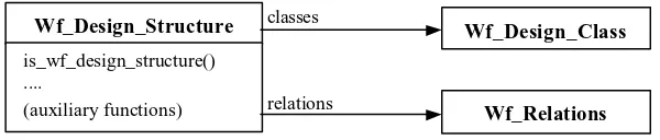
Figure 1 presents an example that is focused on type translation: the Wf_Design_Structure type will be represented by a class called by a similar name. Since the Design_Structure type comprises a collection of Classes and a collection of Relations (Wf_Relations), there will be two state variables in that class, which will be used to relate this class to others, with appropriate names, representing the collection of Classes and the collection of Relations.
In the case of the collection of Classes it will be used the Hash-Map Java type. This structure adequately fits to an RSL Map which has been used in its definition as the Design_Class-scheme shows in section 2.
Since the principal goal of this work is to verify correctness in a design model there is a function in every building block of the formal model whose purpose is checking well-formedness. For example for the Design_Structure to be checked if it is well-formed there is a function called is_wf_design_structure. This function is represented as a method in the class Wf_Design_Structure of the object-oriented model. Functions called by the previous one are represented as private methods in the same class. For every building block there are “auxiliary functions” allowing verification but mainly supplying a shortcut through the whole structure. Those functions are methods included in the interface of the class representing that building block. The same process is applied for the specification of every GoF pattern.
4.VERIFICATION TOOL FOR OOD USING GOF PATTERNS
Basically the tool is divided into two layers: the modelling layer, whose result is a specification of an object-oriented design model provided by a
m
→
Design_Structure = C.Classes x R.Wf_Relations,
Wf_Design_Structure = {| ds : Design_Structure • is_wf_design_structure(ds) |}
Wf_Design_Structure
is_wf_design_structure() ....
(auxiliary functions)
Wf_Design_Class
Wf_Relations
classes
[image:3.595.152.452.680.744.2]graphical component; and the verification layer, which carries out the process of checking the correctness of the design model and also if the design subset related to a specific pattern satisfies the pattern properties.
Specification Layer
Since many tools providing a graphical component for modelling object-oriented design have already been developed with a proved success, we have decided to choose one of them, and thus concentrate the major effort in the field where less work has been delivered. After studying some tools available in the market we have selected a non-commercial tool called FUJABA [15,16,17]. This tool was developed in Java and it may produce a Java specification of the object-oriented design that is modelled by using it.
The functionality of FUJABA is quite similar to our expectations. However, according to our formal basis, a new behaviour needs to be developed in order to be able to represent an entire object-oriented model in which a pattern has been applied.
The extended functionality is related, for example, to the annotations attached to methods of classes. Annotations are used to express how collaborations between classes are carried out. Since our formal model expresses collaborations in a static way, annotations come to fulfil this subject. Other important new behaviour concerns the possibility of selecting a particular pattern from a pattern repository and setting which pattern roles are played by different entities at design level.
Some changes are also necessary, mainly in the notation of the object-oriented model given by a Java specification. An example is the simplification needed when an aggregation relation is
represented, thus complexity of the grammar for a Parser is not increased. Pattern roles and other design or pattern elements will be expressed adding “comments” in the Java specification.
Verification Layer
The component diagram showing the components and their dependencies is presented in figure 2. Each of the components, their interfaces and dependency relationships are described below. Some of them are described in terms of their interfaces and sub-components, and others are informally mentioned for brevity reasons.
• The Coordinator Component
The intent of this component is to coordinate the verification process accordingly using each component at a time.
Once the Java specification from the graphical component is produced, the Coordinator calls the Java Parser and Instantiation Component to obtain an object structure (representing an instantiation of the OOD and Pattern Metamodel Component) as a result. Then the coordinator invokes different behaviours of the object structure in order to verify design constraints.
If the result is successful, the Coordinator will invoke the Pattern Metamodel Component to check the pattern constraints with the aim to assure the correct use of a specific pattern.
• The Java Parser and Instantiation Component
The component should parse the Java code generated by the graphical component in order to create an object structure which represents a valid instantiation of the OOD Metamodel and
Design _Elements _Constructors
OOD Metamodel Component Well-formedness_
Design_Properties
Public_Design _ Properties_ Dependecy_ Relationship Execution_
Management Java Parser and Instantiation Component
Coordinator Component
Pattern_Element_ Constructors
Well-formedness_ Pattern_Properties
[image:4.595.113.478.84.278.2]Patterns Metamodel Component
Pattern Metamodel. The way the component uses services of the last two mentioned components are described later in this section.
Besides, error codes generated during the parse process or the creation of an instance of any metamodel, are returned to the Coordinator Component.
• The OOD metamodel Component
This component corresponds to the Java translation of the OOD formal model presented in section 2. It will be referred in this article using its acronym OOD-M.
The scheme's division presented in section 2 provides us with a useful manner to make an “a priori” partition during the translation process.
Using the scheme division is possible to decompose the OOD-M Component in four subcomponents where Meta_Methods includes the Method scheme functionality, Meta_Class includes the Design_Class scheme functionality, and so on. Figure 3 shows a detailed diagram of this component.
Two different kinds of interfaces and a dependency relationship were identified in the OOD-M Component, as is shown in Figure 2. Following we present a short description of them:
Design_Elements_Constructor Interface Used by: Java Parser Component,
Intent: Provides an interface for constructing elements of the OOD metamodel in order to generate a possible metamodel instantiation. The Parser and Instantiation Component could access directly to the class constructor of the metamodel. If it does so, it might also access to the behaviour of the created object, which should not be allowed. That is why the Instantiation Component should only see a narrow interface, which provides a service of creating an object structure to represent an instantiation of the metamodel.
Data returned: According to the method being invoked, an instance of an element or
composed element of the metamodel is returned.
Well-formedness_Design_Properties Interface
Used by: Coordinator Component,
Intent: Provides an interface for verifying correctness of design properties.
Data returned: Whenever a constraint is violated an appropriate error code is generated. Other facilities of error management are provided as well.
Public Design Properties Dependency Relationship
Used by: Pattern Metamodel Component. The Pattern Metamodel Component is dependent on the OOD-M Component, since it calls specific methods on the component. Although the communication is two-way (since the OOD-M component returns data), the OOD-M Component is not aware of who is calling it and it does not depend on the Pattern Metamodel Component.
Intent: Provides a set of design properties which must be of public access for defining pattern properties.
Data returned: A boolean condition of the invoked property and error codes.
Meta_ Methods
Meta_ Class
[image:5.595.310.532.79.214.2]Meta_ Relation
Figure 3: Component Diagram of OOD-M Component Meta_ Design_ Structure
Figure 4: Component Diagram of Pattern MetamodelComponent Renaming
General Pattern Properties
Properties of a Specific Pattern OOD
Metamodel Component
[image:5.595.104.507.620.734.2]• The Pattern Metamodel Component
This component represents the Java translation of the Renaming scheme and Design_Pattern scheme presented in section 2 and the formal specification of GoF patterns described in [7,8,9]. Thus it is comformed by three subcomponents: Renaming, General Pattern Properties and Properties of a Specific Pattern.
It calls specific methods of the OOD-M component in order to accomplish verification activities of pattern properties. This is shown through a dependency relationship in figure 2.
This component has two interfaces: Patterns Element Constructor Interface and Well-formedness Pattern Properties, their intent and data results are analogous to those described in the OOD-M component.
5.CONCLUSIONS
The main goal of our work is to achieve a more precise but flexible Pattern-Based Design process. For this, we have developed, by means of RAISE [5], a formal basis of an object-oriented design and GoF design patterns [4], which was presented in section 2. In order to provide flexibility we are developing an automatic tool for verifying a correct application of patterns. With this in mind, the abstract formal model, giving the structure for representing a verifiable design model, needs to be concretised. Thus, a translation from the RAISE specification to an Object-Oriented Model is being carried out (see section 3). The main aspects concerning the automatic tool including its structure and its main components have been introduced in Section 4. Very often more than one pattern is needed to solve a design problem. If indeed our tool verifies a single pattern at a time, a piece of work has been already done concerning composition among patterns in [14]. Our current work is intended to be applied, in future, to improve a component development process.
6. REFERENCES
1. Brad Appleton. Patterns and Software: Essential Concepts and Terminology.
http://www.enteract.com/~bradapp/docs, Object Magazine Online (vol.3, nro.5), May 1997.
2. Doug Lea. Patterns-Discussion FAQ. http://g.oswego.edu/dl/pd-FAQ/pd-FAQ.html, December 1999.
3. Robert Zubeck. Much Ado about Patterns. http://www.acm.org/crossroads/xrds5-1. ACM Crossroads Student Magazine, Fall 1998 4. Gamma E., Helm R., Johnson R. and Vlissides
J. Design Patterns - Elements of Reusable
Object-Oriented Software. Addison-Wesley, 1995.
5. The RAISE Language Group. The RAISE Specification Language. BCS Practitioner Series, Prentice Hall, 1992.
6. Andrés Flores, Luis Reynoso and Richard Moore. A Formal Model of Object Oriented Design and GoF Design Patterns. In proceedings of the FME 2001, Formal Methods Europe, Berlin, Germany, LNCS 2021, Springer Verlag 2001, 12-16 March 2001, pp. 223-241.
7. Andrés Flores and Richard Moore. Analisis and Specification of GoF Structural Patterns. In proceedings of 19th IASTED, International Conference on Applied Informatics (AI 2001), Innsbruck, Austria, 19-22 February 2001, pp. 625-630.
8. Luis Reynoso and Richard Moore. A Precise Specification of GoF Behavioural Patterns. In proceedings of SNPD'01, 2nd International Conference on Software Engineering, Artificial Intelligence, Networking & Parallel/Distributed Computing, Nagoya, Japan, 20-22 August 2001, pp. 262-270. 9. Gabriela Aranda and Richard Moore. GoF
Creational Patterns: A Formal Specification. Technical Report 224, UNU/IIST, P.O. Box 3058, Macau, 2000♦.
10. Marco Meijers, Tool Support for Object-Oriented Design Patterns. Master Thesis. Department of Computer Science, Utrecht University, The Netherlands, August 1996, http://www.serc.nl/people/florijn/work/pattern s.html.
11. Andrés Flores, Luis Reynoso and Richard Moore. A Formal Model of Object Oriented Design and GoF Design Patterns. Technical Report 200, UNU/IIST, P.O. Box 3058, Macau, July 2000.
12. Andrés Flores and Richard Moore. GoF Structural Patterns: A Formal Specification. Technical Report 207. UNU/IIST, P.O. Box 3058, Macau, August 2000.
13. Luis Reynoso and Richard Moore. GoF Behavioural Patterns: A Formal Specification. Technical Report 201, UNU/IIST, P.O. Box 3058, Macau, May 2000.
14. Gabriela Aranda and Richard Moore. Formally Modelling Compound Design Patterns. Technical Report 225, UNU/IIST, P.O. Box 3058, Macau. Available at http://www.iist.unu.edu December 2000. 15. Software Engineering Group.FUJABA (From
UML to Java And Back Again). University of
♦ UNU/IIST technical reports are available at
Paderborn, Germany, http://www.uni-paderborn.de/cs/fujaba.
16. Nickel U.A., Niere J., Wadsack J. P., and Zündorf A., Roundtrip Engineering with FUJABA. In Proceedings of 2nd Workshop on Software Re-engineering (WSR), Bad Honnef, Germany, August 2000.
17. Klein T., Nickel U., Niere J., and Zündorf A. From UML to Java and Back Again. Technical Report TR-RI-00-216, University of Paderborn, Germany, September 2000.