Transmission loss of inhomogeneous plates with local resonators:
Methods of theoretical modelling
PACS REFERENCE: 43.55.Rg
Maysenhölder, Waldemar
Fraunhofer Institute for Building Physics
(Director: Prof. Dr. Dr. h.c. mult. Dr. E.h. mult. Karl Gertis) Nobelstr. 12
D 70569 Stuttgart Germany
Tel.: +49 (0) 711 970 3306 Fax: +49 (0) 711 970 3406 E-mail: [email protected]
ABSTRACT
The low-frequency sound transmission loss of plates with resonant inhomogeneities, the spatial extent of which is small compared to the airborne wavelength, may exhibit remarkable devi a-tions from the mass-law behaviour. In principle, these effects can be described by recently de-veloped theories for periodically structured plates. However, since the numerical effort involved is considerable, an additional more elementary model has been developed, in particular for the analysis of measurements, but also as a design tool. It uses harmonic oscillators for both the plate 'skeleton' and the local resonators, which are elastically coupled to the skeleton. Compari-son with measurements indicate that the observed trends are correctly reproduced by the mod-els.
1 INTRODUCTION
It remains a challenge to design plates with a high transmission-loss in the mass-law frequency range without increasing the total mass. Recently, a remarkable concept has been studied by a group of physicists at the University of Hong Kong [1]. A plate made from a 'locally resonant sonic material' consisting of lead spheres, which are coated with silicone rubber and embedded in epoxy, showed an astounding performance (Fig. 1). Between 250 Hz and 500 Hz a significant improvement over the mass law has been achieved followed by some deterioration and a sec-ond smaller improvement above 1 kHz.
In another experiment the authors investigated a "sonic crystal", where coated lead spheres in epoxy had been arranged in a three-dimensional simple-cubic lattice (lattice constant: 1.55 cm). Their measurements indicated two large band gaps around 400 Hz and 1400 Hz, a finding which corresponded well with the calculated band structure. It is pointed out that at 500 Hz the longitudinal wavelength in epoxy is 300 times larger than the lattice constant. The fact that nev-ertheless this fine structure can block sound waves rather efficiently is attributed to the localized nature of the resonances.
Fig. 1: Normal incidence transmission loss of an epoxy plate containing randomly dispersed lead spheres (plate thickness: 21 mm; sphere diameter: 10 mm; thickness of coating: 3.5 mm; dis-tance of spheres: around 20 mm). The straight line follows the mass law for a homogeneous plate with the same average mass per area (47 kg/m²). The data have been taken from Fig. 3 in [1].
2 MODELLING WITH PERIODICALLY STRUCTURED THIN PLATES
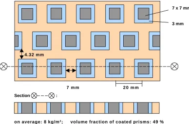
In the first model to be discussed here the epoxy plate with the randomly dispersed lead spheres is idealised as a thin plate with inhomogeneities periodically arranged in a hexagonal manner. This kind of structure may be handled by the computer code HYPERAKUS, which is based on a generalisation of Cremer's treatment of homogeneous thin plates [2]. Since there are no circles available in the current version, a square geometry has been used instead (Fig. 2).
Section :
on average: 8 kg/m²; volume fraction of coated prisms: 49 %
Fig. 2: Idealised structure with two-dimensional periodicity for HYPERAKUS calculation 20
30 40 50 60 70
160 200 250 315 400 500 630 800 1000 1250 1600
Frequency [Hz]
Normal Incidence Transmission Loss [dB]
measurement
mass law
4.32 mm
4.
7 x 7 mm
3 mm
[image:2.596.105.493.479.734.2]Lead
[image:3.596.116.474.182.398.2]The periodic structure causes diffracted waves in addition to the reflected and transmitted waves with homogeneous plates. These diffracted waves are propagative above their cut-on frequencies, whereas below they decay exponentially with distance from the plate surfaces ("nearfields"). For the considered structure the first cut-on frequency is beyond 10 kHz, there-fore the spike in the resulting transmission loss curve (Fig. 3) is exclusively due to nearfields. A behaviour similar to Fig. 1 is found: an improvement over the mass law followed by a deteriora-tion. The second improvement is probably missing because of the thin-plate model, which means no coating and no embedding in the thickness direction.
Fig. 3: Result of HYPERAKUS calculation for the structure in Fig. 2 with 871 nearfields
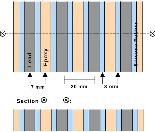
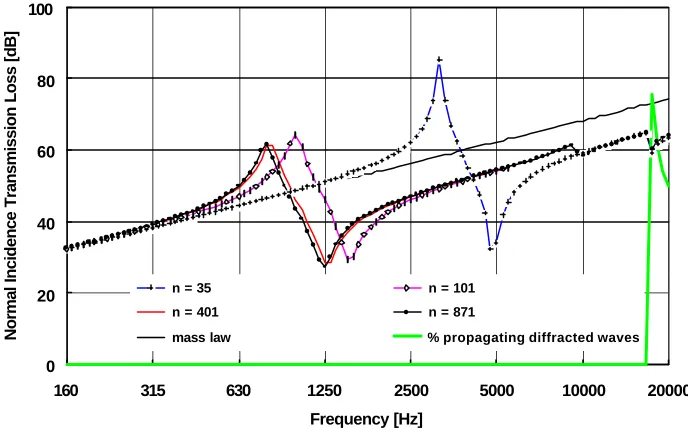
Unfortunately, this result is not fully converged due to limited computing capacity. Therefore, the structure has been simplified further to one-dimensional periodicity (Fig. 4). Now a rather good convergence could be achieved with the maximum possible number of 871 nearfields. Increas-ing the number of nearfields in the calculation leads to a shift of the spike to lower frequencies (Fig. 5). The shape of the transmission loss curve is the same as in the case of two-dimensional periodicity.
Fig. 4: Idealised structure with one-dimensional periodicity for HYPERAKUS calculation
0 20 40 60 80 100
160 315 630 1250 2500 5000 10000 20000
Frequency [Hz]
Normal Incidence Transmission Loss [dB]
HYPERAKUS (2D, n=871)
mass law
% propagating diffracted waves
7 m m 20 mm 3 m m
Section
⊗
⊗
:Epoxy
Lead
[image:3.596.178.440.525.748.2]Fig. 5: HYPERAKUS calculations for the structure of Fig. 4: Convergence with the number of nearfields n
Fig. 6: Displacement pattern of the structure of Fig. 4 at various frequencies (n=871; dashed line: rest position)
Fig. 6 provides a visualisation of the plate motion at selected frequencies. At 328 Hz all parts move in phase albeit with different amplitudes. At 800 Hz, however, the lead and epoxy parts move against each other: a plausible explanation of the transmission-loss maximum. Further increase of the frequency reduces the amplitude of the lead parts, which eventually seem to come to rest. This is the reason why the transmission loss curve remains below the straight line of the mass law.
Although a more realistic modelling of the measurement of Liu et al. [1] is not possible with HYPERAKUS, the essential physics at the transmission-loss maximum is believed to be the same. Closer quantitative agreement may be expected with a model describing thick plates with periodic structure [3], where embedded spheres can be included without principal problems. Unfortunately, the required computing capacity is still much higher than for the two-dimensional HYPERAKUS case.
0 20 40 60 80 100
160 315 630 1250 2500 5000 10000 20000
Frequency [Hz]
Normal Incidence Transmission Loss [dB]
n = 35 n = 101
n = 401 n = 871
mass law % propagating diffracted waves
328 Hz 800 Hz 1.25 kHz ~ 2 kHz
Epoxy
Rubber
[image:4.596.127.471.77.292.2] [image:4.596.120.493.332.565.2]Fig. 7: Harmonic oscillator model with "Master" (1) and "Slaves" (2 and 3)
3 MODELLING WITH HARMONIC OSCILLATORS
[image:5.596.96.479.68.214.2]The simplicity of the displacement patterns shown in Fig. 6 provokes the search after a com-paratively simple theoretical model without the necessity of extensive number crunching. Fig. 7 shows such a model consisting of coupled harmonic oscillators (cf. also [4, 5]). The first har-monic oscillator ("master HO") corresponds to the epoxy part of the plate and the "slaves HO" represent the lead spheres, which are elastically coupled to the "master" by rubber springs. The excitation amplitude of each HO is proportional to its exposed area. This area is zero in the case of the embedded spheres, i. e. the spheres are only excited indirectly by the "master" and not by the incident acoustic wave. In the case of the HYPERAKUS models the lead parts are directly excited, too. For normal sound incidence and identical coated lead spheres one "slave" is suffi-cient.
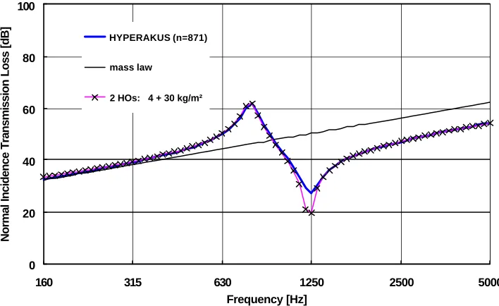
Fig. 8: Results from Fig. 5 (n=871) and from harmonic oscillator model
The agreement between such a HO calculation and the HYPERAKUS result of Fig. 5 is almost perfect (Fig. 8). A significant difference exists only around the transmission-loss minimum. This probably indicates that the damping description with the damping force proportional to the ve-locity of the HO mass should be modified.
0 20 40 60 80 100
160 315 630 1250 2500 5000
Frequency [Hz]
Normal Incidence Transmission Loss [dB]
HYPERAKUS (n=871)
mass law
2 HOs: 4 + 30 kg/m²
Coupled harmonic oscillators in a rigid duct
1
2
3
2 3
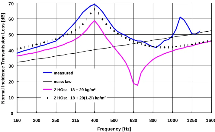
[image:5.596.116.470.423.640.2]Fig. 9: Measurement of Fig. 1 and results from harmonic oscillator model
Can we also reproduce the measurement? From Fig. 9 it is obvious that there is no quantitative agreement. However, the trend is roughly correct. An improvement can be achieved by adding an imaginary mass to the lead HO, but before a more detailed discussion of the merit of this ad-hoc action it should be given a reliable theoretical basis.
4 CONCLUSIONS
Remarkable improvements of the transmission loss of plates in the mass-law frequency range can be accomplished by local resonators with a size much smaller than the wavelengths in-volved. The theoretical description of this effect may proceed along two lines, either by a contin-uum-mechanical approach, which requires considerable numerical resources, or by compara-tively simple models of coupled harmonic oscillators, which admittedly need refinement for a better agreement with measured results. Further steps should include more realistic damping terms and consideration of three-dimensional effects.
REFERENCES
[1] Z. Liu, X. Zhang, Y. Mao, Y. Y. Zhu, Z. Yang, C.-T. Chan, P. Sheng: Locally resonant sonic materials. Science 289 (2000) 1734-1736.
[2] W. Maysenhölder: Sound transmission through periodically inhomogeneous anisotropic thin plates: Generalizations of Cremer's thin plate theory. ACUSTICA • acta acustica 84 (1998), 668-680.
[3] W. Maysenhölder, R. Haberkern: Sound transmission through periodically inhomogene-ous plates: Solution of the general problem by a variational formulation. Submitted to ACUSTICA • acta acustica.
[4] B. M. Efimtsov, L. A. Lazarev: Sound transmission loss of panels with resonant ele-ments. Acoust. Phys. 47 (2001) 291-296.
[5] E. A. Skelton, J. H. James: Theoretical Acoustics of Underwater Structures. Imperial Col-lege Press, London 1997, p. 228f.
0 10 20 30 40 50 60 70
160 200 250 315 400 500 630 800 1000 1250 1600
Frequency [Hz]
Normal Incidence Transmission Loss [dB]
measured
mass law
2 HOs: 18 + 29 kg/m²
[image:6.596.115.471.75.294.2]