Functionalized adsorbent materials using supercritical CO2
194
0
0
Texto completo
(2) Summary. Historically, porous silica (SiO2) is one of the most used adsorbents for a wide variety of processes in the industry. However, the fast grown on the demand of new nanotechnology based materials and sustainable green processes have made necessary the development of adsorbents with improved physico-chemical properties. One of the most applied options to modify porous silica is the incorporation on the surface of organic functional molecules, giving place to hybrid materials, in which the properties of both components are combined. In this doctoral thesis, supercritical carbon dioxide (scCO2) has been used as the solvent to carry out the functionalization processes. Carbon dioxide is a sustainable solvent and its use has been preferred in front of toxic organic liquid solvents, often applied in the traditional methods of synthesis. Amorphous silica matrices with structural ordered pores (MCM-41, 4 nm) and disordered pores (silica gel, 4-9 nm) were selected for the functionalization processes. Besides, the properties conferred by functionalization to microporous crystaline zeolites have been preliminary studied. The modifying agents applied in this thesis were. either. alkyl. (octyltriethoxysialane). or. amino. (methylaminopropyltrimethoxisilane) silane and aziridine. The later compound is a monomer which polymerizes in presence of CO2, leading to hyperbranched polyethyleneimine (PEI) with multiple amino groups formed into the silica pores. This novel method only requires compressed CO2 as the reagent and the catalyst of the polymerization reaction of aziridine, which usually requires the use of organic solvents, a solid catalyst, high temperatures and long processing times. The functionalization of porous silica with aminosilane in scCO2 is more complex than the case of alkysilanes due to the high reactivity between amino groups and CO2 to form unsoluble carabamate species. However, in this study a protocol was designed to partially inhibit carabamate formation by controlling the pressure and temperature of the reaction media. The obtained materials were characterized using solid state characterization tools: low temperature N2 and CO2 adsorption, thermal analysis, infrared spectroscopy and X-Ray diffraction. Moreover, modeling and simulation i.
(3) methods were used as complementary tools that allowed the study of this complex systems with a high level of detail. The alkyl chain of the alkylsilane induced to the porous system a hydrophobic behavior, hence, obtaining materials candidates for oil adsorption. The functionalization with organic molecules containing the amino group allowed the preparation of materials for the adsorption and separation of CO2 from diluted gases (CO2 sequestration). The CO2 adsorption properties of the synthesized aminosilicas were evaluated combining experimental adsorption tools with molecular simulations. The characterization of these materials was based on the evaluation of the overall CO2 adsorption capacity and the influence of the temperature, the selectivity of the CO2 adsorption in gas mixtures, the stability in the cyclic adsorption/desorption process and the kinetics, which were determined by performing both microbalance and CO2 adsorption isotherms at different temperatures.. ii.
(4) Table of contents pag. Summary Index List of symbols, abbreviations and acronyms INTRODUCTION. i iii viii 1. THESIS GOALS. 3. OUTLINE OF THE THESIS. 4. REFERENCES. 6. CHAPTER 1 POROUS MATERIALS 1.1 INTRODUCTION TO POROUS MATERIALS. 7. 1.2 METHODS TO CREATE PORES. 9. 1.3 ORGANIC POROUS MATERIALS. 10. 1.3.1 Covalent organic frameworks. 10. 1.3.2 Porous polymers. 11. 1.3.2.1 Micro- and mesoporous permanent porous polymers. 11. 1.3.2.2 Polymer foams. 12. 1.4 INORGANIC POROUS MATERIALS. 13. 1.4.1 Carbon materials. 13. 1.4.2 Silica. 14. 1.4.2.1 Sol-gel process. 15. 1.4.2.2 Silica nanoparticles. 18. 1.4.2.3 Porous silica gels and aerogels. 19. 1.4.2.4 Ordered mesoporous silica. 20. 1.4.3 Silicates. 21. 1.4.3.1 Zeolites. 22. 1.4.3.2 Clay minerals. 23. 1.4.4 Meso-macroporous minerals. 24.
(5) TABLE OF CONTENTS 1.5 ORGANIC-INORGANIC POROUS MATERIALS 1.5.1 Direct synthesis. 24 25. 1.5.1.2 Metal Organic Frameworks. 25. 1.5.1.3 Organically modified silica. 26. 1.5.2 Post-synthesis functionalization: silanization. 26. 1.6 POROUS MATERIALS USED IN THIS WORK. 29. 1.6.1 Mesoporous and meso/microporous silica gels. 30. 1.6.3 Mesoporous MCM-41. 31. 1.6.4 Microporous zeolite. 31. 1.7 CONCLUSIONS. 32. 1.8 REFERENCES. 33. CHAPTER II COMPRESSED CO2: PROPERTIES, APPLICATIONS AND HIGH PRESSURE TECHNOLOGY 2.1 INTRODUCTION: PROPERTIES OF SUPERCRITICAL FLUIDS. 40. 2.1.1 Single phase and tunable density. 41. 2.1.2 Negligible surface tension and low viscosity. 42. 2.1.3 Low critical temperature and pressure. 42. 2.1.4 Green solvent. 43. 2.1.5 Solvent properties of supercritical CO2. 44. 2.1.6 Production of CO2. 44. 2.2 STUDY OF THE DENSITY ENHANCEMENT ON CONFINED SUPERCRITICAL CO2 USING AN EQUATION OF STATE. 44. 2.3 APPLICATIONS OF SUPERCRITICAL CO2. 47. 2.3.1 Extraction of organic compounds. 48. 2.3.2 Mobile phase in chromatography. 49. 2.3.3 Supercritical CO2 applied to polymers. 49. 2.3.4 Supercritical CO2 in the preparation of micro- and nanoparticles. 50. 2.3.5 Processing and modifying porous materials in supercritical CO2. 51. iv.
(6) TABLE OF CONTENTS 2.4 HIGH PRESSURE EQUIPMENTS: EQUIPMENT BUILDING MATERIALS AND ELEMENTS. 52. 2.4.1 Materials. 53. 2.4.2 Vessels and sealing systems. 53. 2.4.3 Stirring mechanism and impeller types. 54. 2.4.4 Pressure pumps. 55. 2.4.5 High pressure tubing and valves. 56. 2.4.6 Pressure and flow measurement devices. 57. 2.4.7 Heating systems. 57. 2.4.8 Pressure release systems. 58. 2.5 HIGH PRESSURE SYSTEMS USED IN THIS WORK. 58. 2.5 CONCLUSIONS. 62. 2.6 REFERENCES. 63. CHAPTER III FUNCTIONALIZATION OF POROUS SUBSTRATES USING COMPRESSED CO2 3.1 INTRODUCTION. 67. 3.2 SOLID STATE CHARACTERIZATION TOOLS. 68. 3.2.1 Confirming the presence of organic moieties: Fourier Transform Infrared Spectroscopy. 68. 3.2.2 Loading concentration and thermal stability: thermogravimetric analysis. 69. 3.2.3 Determining the textural properties: N2 adsorption isotherms. 70. 3.2.4 Molecular simulations: structural models of the porous media. 71. 3.2.4.1 Zeolite Y. 71. 3.2.4.2 Amorphous silica gel. 72. 3.2.4.3 MCM-41. 73. 3.2.5 Molecular weight determination of polymer: Static Light Scattering and Maldi-ToF. 73. 3.3 SUPERCRITICAL FUNCTIONALIZATION USING ORGANOSILANES v. 74.
(7) TABLE OF CONTENTS 3.3.1 Alkylsilanes. 74. 3.3.1.1 Functionalization procedure. 74. 3.3.1.2 Infrared characterization. 78. 3.3.1.3 Thermal analysis and grafting density. 78. 3.3.1.4 Textural properties. 82. 3.3.1.5 Molecular simulation. 83. 3.3.2 Aminosilane. 94. 3.3.2.1 Behavior of the aminosilane in compressed CO2. 96. 3.3.2.2 Functionalization procedure. 97. 3.3.2.3 Infrared characterization. 99. 3.3.2.4 Thermal analysis and grafting density. 100. 3.3.2.5 Influence of processing parameters on aminosilane uptake. 104. 3.3.2.6 Textural properties. 106. 3.3.2.7 Molecular simulation. 109. 3.4 POLYMERIZATION OF ETHYLENEIMINE UNDER COMPRESSED CO2. 114. 3.4.1 Functionalization procedure. 115. 3.4.2 Polymerization mechanism. 116. 3.4.3 Polymer molecular weight and structure. 117. 3.4.4 Thermal analysis and grafting density. 119. 3.4.5 Comparison of the thermal behavior with similar samples from literature. 120. 3.4.6 Textural properties. 121. 3.5 CONCLUSIONS. 121. 3.6 REFERENCES. 125. CHAPTER IV ADSORPTION PROPERTIES 4.1 INTRODUCTION. 132. 4.2 ADSORPTION CHARACTERIZATION TOOLS. 133. 4.2.1 Karl Fischer method: water uptake. 133 vi.
(8) TABLE OF CONTENTS 4.2.2 Gas adsorption analyzer: CO2 adsorption isotherms. 135. 4.2.3 Microbalance: CO2/N2 adsorption/desorption cycles. 135. 4.2.4 CO2 molecular simulations. 136. 4.3 WATER UPTAKE IN HYDROPHOBIC POROUS MATERIALS. 138. 4.4 CO2 ADSORPTION ON AMINOSILANE FUNCTIONALIZED SILICA. 141. 4.3.1 CO2 adsorption isotherms. 142. 4.3.2 Molecular simulation. 146. 4.3.2.1 MCM-41. 146. 4.3.2.2 SG40. 148. 4.3.3 Cyclic performance and separation from N2. 148. 4.3.3.1 Influence of amine loading. 149. 4.3.3.2 Influence of the temperature. 150. 4.3.3.3 Comparison to literature data. 150. 4.3.3.4 CO2 adsorption and desorption rates. 154. 4.5 CO2 ADSORPTION ON POLYETHYLENEIMINE FUNCTIONALIZED SILICA. 156. 4.4.1 CO2 adsorption isotherms. 156. 4.4.1.1 Influence of the temperature on the adsorption. 158. 4.4.1.2 Differences on the CO2 adsorption by CC and MCM-41 samples. 160. 4.4.2 Cyclic performance and separation from N2. 161. 4.4.2.1 CO2 adsorption and desorption rates. 162. 4.4.2.2 Comparison to literature data. 164. 4.6 COMPARISON OF THE CO2 ADSORPTION BETWEEN AMINOPOLYMER AND AMINOSILANE SAMPLES. 166. 4.6.1 Relationship between the adsorption of N2 and CO2 from aminosilane and aminopolymer samples. 167. 4.6.1 Overall CO2 adsorption. 168. 4.7 CONCLUSIONS. 170. 4.8 REFERENCES. 172. CHAPTER V vii.
(9) TABLE OF CONTENTS CONCLUSIONS AND FUTURE WORK. viii. 175.
(10) Symbols. ds. Deposited silane (gs g-1). gs. Grafted molecules (g). k. Boltzmann’s constant. Mw. Molecular weight. n. Molecule density in lattice gas. p. Density of particles in porous matrix. P. Pressure (Pa). Pc. Critical pressure (Pa). Pr. Reduced pressure. P/P0. Relative pressure. Pd. Pore diameter (nm). Sa. Surface area (m2 g-1). T. Temperature ( ºC). Tg. Glass transition temperature (ºC). Tc. Critical temperature (ºC). Tr. Reduced temperature. Vp. Pore volume (cm3 g-1). Vmp. Micropore volume. z. Lattice coordination number.
(11) Greek letters Φ. Scaling factor. ρOH. Hydroxyl density (OH nm-2). ρgraft. Grafting density (molec nm-2). β. 1/kT. µ. Chemical potential. Г. Fluid-solid coupling parameter in lattice gas Nearest neighbor coupling parameter Density. Subscripts c. Critical property. Superscripts ‘. Dimensionless property. x.
(12) Abbreviations and acronyms. BET. Brunauer-Emmett-Teller. BJH. Barret Joyner and Halenda. CC. Clean Cat. CDCB. Couple-Decoupled Configurational Bias. CNT. Carbon Nanotube. COF. Covalent Organic Framework. EA. Elemental Analysis. Et. Ethanol. Eth. Diethyl ether. FTIR. Fourier Transform Infrared. GAS. Gas Anti-Solvent. GMC. Grand Canonical Monte Carlo. GWP. Global Warming Potential. HTSCD. High Temperature Supercritical Drying. IR. Infrared. KF. Karl-Fischer. LTSCD. Low Temperature Supercritical Drying. MALDI Tof. Matrix-Assisted Laser Desorption/Ionization. MCM. Mobil Composition of Matter (type of mesoporous silica) xi.
(13) Me. Methanol. MIP. Mercury Intrusion Porosimetry. MMS. Mesoporous molecular Sieve. MOF. Metal Organic Framework. MWCN. Multi Walled Carbon Nanotube. OMS. Ordered Mesoporous Silica. PEI. Polyethyleneimine. PCA. Precipitation with a Compressed Antisolvent. PGSS. Particles from Gas Saturated Solutions. PID. Proportional Integral Derivative Controller. RESS. Rapid Expansion of Supercritical Solutions. SAS. Supercriticial Anti-solvent. SB. Silica Blue. SBA. Santa Barbara Amorphous (type of mesoporous silica). ScCO2. Supercritical Carbon Dioxide. SCF. Supercritical Fluid. SG40. Silica Gel 40. SWCN. Single Walled Carbon Nanotube. TEM. Transmision Electronic Microscopy. TEOS. Tetraethyl orthosilicate. TGA. Thermogravimetric Analysis xii.
(14) TMOS. Tetramethylorthosilicate. XRD. X-ray diffraction. ZSM. Zeolite Socony Mobil. ZY. Zeolite Y. xiii.
(15) INTRODUCTION. The focus of this thesis is the synthesis and characterization of organic-inorganic porous materials for adsorption applications. For this purpose, porous silica were used as the inorganic host substrates to be modified with organic functional molecules using a new procedure for the functionalization. The impregnation of organic functional groups into porous systems leads to a final products with interesting properties that can be used in diverse processes, such as catalysis [1], adsorption [2, 3], separation [4], drug delivery [5] and to develop sensors [6]. Common routes to graft organic functional groups on the internal surface of porous silica are based on the use of organic solvents that are highly pollutant. Thus, one of the main goals of this thesis, based on the search of new and alternative synthesis processes, is the use of supercritical CO2 (scCO2) as a green technology to prepare functionalized porous sorbents. Since the discovery of supercritical fluids in 1822 by Baron Charles Cagniard, this technology has been used to replace some conventional solvents applied in the manufacturing of different materials by scCO2. For instance, the extraction of caffeine from coffee [7], one of the most consumed beverages in the world, or the recent use of scCO2 to extract trichloroanisole from cork stoppers [8], a non desired molecule in the wine industry, gives us an idea of the importance of the use of supercritical CO2 as an industrial solvent. In this thesis, supercritical CO2 has been used as the solvent media to modify porous silica with alkylsilanes in order to prepare hydrophobic sorbents; and with aminosilanes and aminopolymers to develop materials for CO2 adsorption applications. The use of solid sorbents for CO2 adsorption and separation processes arises as a potential solution to mitigate the rapid increase of the CO2 concentration in the atmosphere, negatively influencing the global climate change [9]. In order to slow this increase, great efforts are being done to reduce the anthropogenic CO2 emissions. Large emission point sources, such as fossil-fuel-based power generation facilities are the first targets [10, 11]. In addition, CO2 is also separated and purified for other several industrial applications, and the process to be used for this separation depends on the source and the final application. The materials.
(16) INTRODUCTION. applied for CO 2 adsorption and separation can be classified depending on t heir way t o incorporate CO2. Figure 1.1 Common CO2 sorbents.. Ideally, a go od CO2 sorbent should e xhibit a fast sorption and desorption kinetics, a large sorp tion capacity , an infinite regenerability and stabili ty. Aqueous amines ar e amongst the most used materials applied at an industrial sca le. Pri mary and sec ondary amines can react di rectly with CO 2 to pr oduce carbamates through th e formation of zwitterionic in termediates. The CO 2 is released upon heatin g the carba mate. The use of aqueous amines entails problems relat ed to t he great energy r equired to de sorb the molecule due to the high heat of adsorption of water, the energy needed to break the strong bond formed between C O2 and th e amine that c auses losses due to amine vo latility, oxidative degradation and stability problems [11]. Hybrid aminosilica materials are a class of sorbents merged to overcome some of the problems related to the use of aqueous amines. The immobilization of a minosilanes on the internal surface of porous silica has several advantages, such as th e less energy required to relea se th e captured CO2 and a better thermal stability [12].. 2.
(17) INTRODUCTION. THESIS GOALS This PhD thesis has the following scientific goals: . To develop a generic scCO2 process for the surface functionalization of meso- and microporous silica with organic functional molecules, in order to improve or modify their properties as sorbents.. . To obtain quality sorbents, i.e. with a homogenous distribution of the impregnated organic molecules and with a high thermal stability, exhibiting: (i) hydrophobic properties by functionalization with alkylsilanes, and (ii) CO2 adsorption properties by functionalization with aminosilanes and aminopolymers.. . To study the behavior of amino compounds in scCO2 in order to overcome the formation of insoluble species by controlling the operating conditions of pressure, temperature and the use of co-solvents.. . To demonstrate that scCO2 is an advantageous and effective alternative to liquid organic methods for the preparation of organic-inorganic porous materials.. . To study the physicochemical properties and the improvement of the modified sorbents with respect to bare materials in their adsorption of H2O, N2 and CO2.. . To obtain quantitative predictions of the adsorption of gases on functionalized silicas and to provide new insights in the adsorption mechanisms through the use of molecular simulations. . To predict thermodynamic properties of bulk- and single component adsorption systems through the use of an equation of state.. The following technical achievements were reached to meet the above mentioned objectives: . Engineering of flexible bench-scale facilities for batch production using scCO2 as a solvent and reaction media.. . Engineering of high pressure instrumentation for organic compounds phase equilibria and solubility behavior in scCO2.. . Development of protocols for designing and evaluating the surface modification processes using scCO2 as the reaction media. 3.
(18) INTRODUCTION. . Development of protocols and methods for off-situ materials characterization: infrared. spectroscopy,. thermogravimetric. analysis,. differential. scanning. calorimetry, Karl-Fischer tritation method for water determination, lowtemperature N2 adsorption/desorption, CO2 adsorption measurements at a wide range. of. temperatures,. microbalance. measurements. for. cyclic. CO2. adsorption/desorption under a gas mixture, X-ray diffraction, MALDI ToF and static light scattering. . Development of theoretical structural models of the porous systems using atomistic procedures (f.i. hard-sphere model, LJ interactions).. . Development of the simulation tools based on the Monte Carlo method and using the grand canonical ensemble for the carbonation reaction.. . Establishing the theoretical transformation steps required to transform the model parameters of the mean field equation of state into real parameters of the fluid of interest.. OUTLINE OF THIS THESIS This brief introduction aims at establishing the contents and the main goals that the reader will find throughout this thesis. In the next chapters, the following contents are developed: Chapter I - Porous materials, contains a classification of the porous mater and a short description of their chemical composition, synthesis methods and applications. This chapter has a special focus in porous silica and in the selected porous systems used in this work. Relevant information of their textural properties is also given. Chapter II - Supercritical CO2: properties, applications and high pressure techonology, describes the thermophysical properties of supercritical CO2 and the advantages of using it in chemical processes. It also presents the study of the thermodynamic properties of supercritical CO2 confined in porous media by using a mean field equation of state. The equipment building materials and the elements required to set up a supercritical fluid process are depicted. A detailed description of the equipment and the different configurations used in this work is provided in this chapter. 4.
(19) INTRODUCTION. Chapter III - Functionalization of porous substrates using supercritical CO2, offers an initial description of the solid state characterization tools used to evaluate the general characteristics of the porous substrates. The experimental functionalization procedures are also described, giving the essential information of the working operation conditions and the experimental set up. In each section, characterization results confirming the presence of organic moieties after the functionalization and the textural properties of the processed porous substrate are given for the different materials prepared. Chapter IV, Adsorption properties, is focused on the experimental characterization of the synthesized materials from the application point of view i.e. hydrophobicity, water uptake and CO2 adsorption. A special attention is given in this chapter to the materials designed for CO2 adsorption properties, comparing the data with simulation results. Data related to prepared products adsorption capacity, the effect of temperature on the adsorption, the efficiency, the rates of adsorption and cyclic adsorption/desorption behavior under a mixture of gases are shown. Molecular simulations are used to obtain relevant information on the adsorption properties of the porous systems. A wide comparison of the adsorption properties of the materials synthesized in this work and the materials from the literature obtained using more conventional synthesis procedures is finally offered in this chapter. Chapter V, Conclusions and future work, provides the general conclusions of this thesis and the research lines that have been opened to continue with further research.. 5.
(20) INTRODUCTION. REFERENCES 1.. A.P. Wight and M.E. Davis, Design and Preparation of Organic−Inorganic Hybrid Catalysts. Chemical Reviews, 2002, 102(10), 3589.. 2.. J. Evans, A.B. Zaki, M.Y. El-Sheikh, and S.A. El-Safty, Incorporation of Transition-Metal Complexes in Functionalized Mesoporous Silica and Their Activity toward the Oxidation of Aromatic Amines. The Journal of Physical Chemistry B, 2000, 104(44), 10271.. 3.. R. Voss, A. Thomas, M. Antonietti, and G.A. Ozin, Synthesis and characterization of highly amine functionalized mesoporous organosilicas by an "all-in-one" approach. Journal of Materials Chemistry, 2005, 15(37), 4010.. 4.. S. Yoo, J.D. Lunn, S. Gonzalez, J.A. Ristich, E.E. Simanek, and D.F. Shantz, Engineering Nanospaces: OMS/Dendrimer Hybrids Possessing Controllable Chemistry and Porosity. Chemistry of Materials, 2006, 18(13), 2935.. 5.. M. Vallet-Regí, M. Colilla, and B. González, Medical applications of organic-inorganic hybrid materials within the field of silica-based bioceramics. Chemical Society Reviews, 2011, 40(2), 596.. 6.. S. Wang, Y. Kang, L. Wang, H. Zhang, Y. Wang, and Y. Wang, Organic/inorganic hybrid sensors: A review. Sensors and Actuators B: Chemical, 2013, 182(0), 467.. 7.. H. Peker, M.P. Srinivasan, J.M. Smith, and B.J. Mccoy, Caffeine extraction rates from coffee beans with supercritical carbon dioxide. AIChE Journal, 1992, 38(5), 761.. 8.. M.K. Taylor, T.M. Young, C.E. Butzke, and S.E. Ebeler, Supercritical fluid extraction of 2,4,6trichloroanisole from cork stoppers. Journal of Agricultural and Food Chemistry, 2000, 48(6), 2208.. 9.. Ipcc, Climate change 2007: synthesis report. COntribution of Working Groups I, II and III to the Fourth Assesment Report of Intergovernmental Panel on Climate Change, 2007: Geneva, Szwitzerland.. 10.. Ipcc, Carbon Dioxide Capture and Storage vol I and II, B.M.O.D.H.d.C.M.L.L. Meyer, Editor 2005: USA.. 11.. M.E. Boot-Handford, J.C. Abanades, E.J. Anthony, M.J. Blunt, S. Brandani, N. Mac Dowell, J.R. Fernandez, M.-C. Ferrari, R. Gross, J.P. Hallett, R.S. Haszeldine, P. Heptonstall, A. Lyngfelt, Z. Makuch, E. Mangano, R.T.J. Porter, M. Pourkashanian, G.T. Rochelle, N. Shah, J.G. Yao, and P.S. Fennell, Carbon capture and storage update. Energy & Environmental Science, 2014, 7(1), 130.. 12.. S. Choi, J.H. Drese, and C.W. Jones, Adsorbent Materials for Carbon Dioxide Capture from Large Anthropogenic Point Sources. ChemSusChem, 2009, 2(9), 796.. 6.
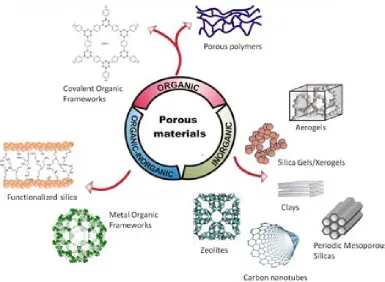
(21) CHAPTER I POROUS MATERIALS. This chapter reviews the family of porous materials, including their main properties, design and synthesis, and applications. In the first sections the main concepts of porous materials and the methods to obtain porous materials, with an special focus in the templating method, are described. Porous materials have been classified into three groups according to their chemical composition. The first group, the organic porous materials comprises covalent organic frameworks and porous polymers. The second group corresponds to the large family of inorganic porous materials, which includes carbon materials, silica, silicates and other minerals. Finally, the last group is formed by the organic-inorganic porous materials which have been classified by their synthesis method into metal organic frameworks and functionalized substrates. The bench of porous materias used in this work, belonging to the categories of silica and silicates, either pristine or functionalized, are described in detail in the last section..
(22) Chapter I. POROUS MATERIALS. 1.1 INTRODUCTION TO POROUS MATERIALS A porous material is a solid with pores, i.e., cavities, channels or interstices, which are deeper th an t hey are wide [1]. Pores are classified according to th eir availability to an external fluid (Fig. 1.1a), to their size size or to the chemical composition.. Availability to external fluid: - Open po res, those with a continuous chann el of communication with the external surface of the solid. They can be open at two ends (through pores (i) ) or only at one end (blind pores (ii)). - Closed pores, those totally isolated from their neighbors (iii). Shape: Pores can also be classified according to their shape (Fig. 1.1b) into (i) cylindrical, (ii) slit, (iii) ink bottle, (iv) funnel shaped and (v) irregular. Two important features are commonly considered in the classification of porous matter, the pore size and the chemical composition of the network material . Both para meters significantly influence th e phy sicochemical behavior of poro us materials in different industrial app lications, such as. sorption, cata lysis, molecular sievin g or membrane. separation.. Figure 1.1 Classification of pores according to: a) the pore opennning, being (i,ii) open pores and (iii) closed pores, and b) the pore shape, including (i) cylindrical, (ii) slit, (iii) ink bottle, (iv) funnel shapped and (v) irregular pores.. 7.
(23) Chapter I. POROUS MATERIALS. Pore size: The classification of th e po res according t o th eir diameter is established by t he International Union of Pure and Applied Chemistry (IUPAC) [2]: - Micropores: pores smaller than 2 nm. - Mesopores: pores between 2 and 50 nm. - Macropores: pores larger than 50 nm. Most porous materiales have po res involving several of the above mentioned pore diameter r anges. An add itional representative characteristic of porous materials is the porosity, defined as the ratio of the empty pore volume to the total volume of the solid. Chemical composition of the network: Porous materials can be organic, inorganic or hybrid organic-inorganic (Fig. 1.2).. Figure 1.2 Examples of porous materials class ified by their network composition in o rganic, inorganic and hybrid organic-inorganic.. 8.
(24) Chapter I. POROUS MATERIALS. - Important gr oups of materials f rom the or ganic class are cov alent organic frameworks and porous polymers [3]. - The inorganic type is the br oadest class of porous ma tter and includes z eolites, microporous carbons, clay minerals, the large family of micro and mesoporous silicas, etc [4]. - The organi c-inorganic po rous hybrids comprise metal or ganic frameworks and functionalized inorganic porous materials as most respresentative family members [5]. 1.2. METHODS TO CREATE PORES Several routes have been designed to prepare po rous materials, such as the sol -gel technique, the foaming and templating procedures, the direct synthesis or the Schiff-base chemistry [4]. The sol -gel pr ocess is a method commonly used t o produce porous solid materials from alkoxides, particularly for the fabrication of oxides of silicon and titanium. This procedure will be further described in the section dedicated to porous silica products. The tem plating-fabrication strateg y is. the most widely us ed method, due to. its. applicability to process a large variety of different porous netwo rk compositions with a wide range of pore size and well-defined pore morphologies [6]. The templating concept is based on the condensation of the end product precursors on the surface of a template that is later removed, thus, forming the void space of the porous m aterial (Fig. 1.3). The po res created have a shap e and size similar to the template used . Some c ommon te mplates are organic m olecules, micelles formed by surfactants and in organic porous materials. The template fabrication method is applied to the s ynthesis of zeolites and zeolitic products (materials wi th a zeolite-type framework structu re), ordered m esoporous silica materials, porous carbons and porous polymers.. Figure 1.3 Scheme of the templating method. The end product precursor condensates around the template and, then, the template is removed by either calcination or solvent extraction.. 9.
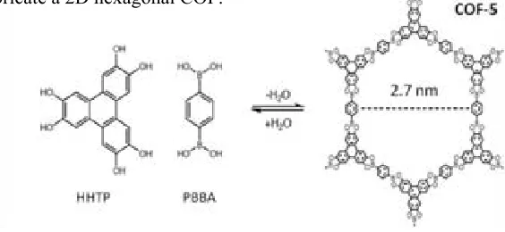
(25) Chapter I. POROUS MATERIALS. 1.3 ORGANIC POROUS MATERIALS 1.3.1 Covalent organic frameworks Covalent or ganic frameworks (C OFs) are 2D or 3D crystalline com pounds, entirely composed by lig ht ele ments (H, B, C, N and O) , and constructed by ass embling organic building unit s via covalent bo nds [3, 7]. The bu ilding units are rigid or ganic frag ments, most of them boronic acids and catechols. Fig. 1.4 shows an example of the building units used to fabricate a 2D hexagonal COF.. Figure 1 .4 Example of a hexagonal 2D COF (COF -5) prepared using a solv othermal condensation reaction between PBBA (a compound composed of a benzene ring with two boronic acid groups) and HHTP (a fla t trigonal buil ding block compos ed of four fused benzene rings wit h two O H groups at each corner) [7].. The wide variety of structural configurations existing for the building fragments offers a enormous versatility to tu ne the pores and functionalities of COFs . COFs have a permanent porosity with pores in the micropore or low size mesopore range, up to 4-5 nm, as well as high chemical and thermal stabilities. Surface areas are tunable between 500 and 4200 m2 g-1. COFs are prepared by mechanochemical synthesis through polycondensation reactions under th ermodynamic control [8]. The molecular leng th of th e building unit s governs the pore size of COFs, while th e shap e of the bu ilding units determines the topology of the porous structures. Schiff-base chemistry is also applied to construct COFs [9, 10]. The possibility of tunning the textural properties of COF materials have made them strong candidates in applications for gas storage (including hydrogen, ammonia, methane and carbon dioxide), adsorption and catalysis [7]. 10.
(26) Chapter I. POROUS MATERIALS. 1.3.2 Porous polymers 1.3.2.1 Micro and mesoporous permanent porous polymers There are two main strategies for the synthesis of polymers with microporosity [11]. In the first one, an amorphous hypercrosslinked polymer i s formed in th e presence of a solvent that swells the network. After solvent removal, the extensive crosslinking reaction prevents the polymer chains from collapsing and a microporous material with high thermal stability is obt ained. An important example is hypercrosslinked polystyrene (Fig. 1.5a) which is commercialized with a pore vo lume of 0.5-0.7 cm 3 g-1 [11]. Hy percrosslinked polymers are currently applied as adsorbents of organic vapors and organic contaminants from water, as well as for hydrogen storage [12].. Figure 1.5 Examples of fabrication methods for permanent porous pol ymers: (a) Friedel-Craft alkylation s ynthesis of h ypercrosslinked polystyrene [11], (b) g eometrical const rains applied in the s ynthesis of Te flon AF 240 0 [13], and (c) examples of different geometr ies obta ined for diblock copolymers [14].. 11.
(27) Chapter I. POROUS MATERIALS. The second strategy for microporous polymer preparation is based on the possibility of using solely the geometry of the used monomers to define the microporosity, without the need of a template or blowing agent. The open void arises from the contorted molecular structure that prohibits an efficient packing of chains in the solid state. These polymers are prepared using a combination of hydroxylated and fluorinated or chlorinated aromatic monomers [15]. They exhibit surface areas between 500 and 1700 m2 g-1. There have been developed several microporous glassy polymers, which exhibit remarkably high gas permeability. Notable amongst these is the 2,2-bistrifluoromethyl-4,5-difluoro-1,3dioxole–tetrafluoroethylene copolymer, designated as Teflon AF 2400 by Du Pont (Fig. 1.5b) that possesses high thermal stability and low reactivity towards acids, bases and oxidizing reagents [13]. Permanent mesoporous polymers are block copolymers, comprising two or more incompatible homopolymer subunits linked by covalent bonds (Fig. 1.5c) [16]. Block copolymers can yield a large variety of morphologies, including spheres, cylinders, bicontinous gyrois, lamellaes, etc (Fig. 1.5c), with space domains in the order of 5-35 nm [14]. Block copolymers are commercially available, being important examples thermoplastic polyurethanes, polyesters and polyamides. 1.3.2.2 Polymer foams Polymer foams are structures formed by using chemical or physical blowing agents, together with especific nucleation agents and stabilizers [17]. Some common polymeric foams are polystyrene, polyurethane, polyethylene and polypropylene. Recently, the use of compressed carbon dioxide (CO2) is a common method to prepare foamed amorphous or semicrystalline polymers, especially for biological applications [18]. According to this method, the polymer is saturated with compressed CO2 at a constant temperature and pressure. Then the system is brought to supersaturation either by reducing the pressure or by increasing the temperature resulting in the nucleation and growth of the pores [19, 20]. Foamed polymers find applications in gas storage and separation, thermal insulation, catalysis, sporting equipment, tissue engineering, etc. 12.
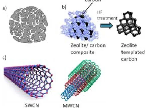
(28) Chapter I. POROUS MATERIALS. 1.4 INORGANIC POROUS MATERIALS 1.4.1 Carbon materials Important microporous carbon m aterials are activated carbons and carbon nanotu bes [21, 22]. Activated carbon is produced from vegetals (wood, coconut shells, etc.), coal or polymers by a two -step pr ocess, involving carbo nization at 45 0-900 º C in an inert atmosphere followed by an activation attained at 600-1200 ºC in an oxidizing atmosphere [23]. During th e carbonization proc ess, most of the noncarbon elements such as oxy gen, hydrogen, and nitrogen are eliminated as volatile gaseous species creating interstices and, thus, microporosity (Fig. 1.6a). Activated carbons display surface areas from 500 to 1400 m2 g-1 and are characterized by a high hydrophobicity and an elevated corrosion resistance. Porous carbon ma terials can be also fabricated with un iform micro- and mesopores by using the template synthesis method and zeolites or m esoporous silicas as the template (Fig. 1.6b) [24]. Aside from zeolites, activated carbons represent the class of microporous materials with the highest industrial si gnificance, partl y because of th eir low pr oduction costs. They are applied in gas separation and adsorption processes, for water purification, as a catalyst supports or as a hosts for the immobilization of biomolecules for biosensors, in electrodes for electrochemical double layer capacitors and in fuel cells [21].. Figure 1.6 Representation of carbon materials: (a) disordered microporous activated carbon, (b) periodic c arbon pre pared using the template m ethod, and (c) single (SW CN) and multiwalled (MWCN) carbon nanotubes.. 13.
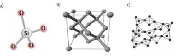
(29) Chapter I. POROUS MATERIALS. Carbon nanotubes (CNT s) are allotropes of c arbon with cylindrical structures and inherent po rosity (Fig. 1.6c). In sing le-walled CNTs, the po re sizes are in two main ranges: < 5 nm and 10−100 nm [25]. Techniques such as arc discharge, high-pressure carbon monoxide disproportionation and che mical vapor dep osition are used to pr oduce nanotubes in commercial quantities. CNTs show high thermal and electrical conductivity, with applications in electronics and ele ctrochemical. Moreover, nan otubes are used as a mechanical r einforcement in hi gh perfo rmance c omposites, energy storag e and for biological and chemical applications [26] 1.4.2 Silica Silica is the common name for materials composed of silicon dioxide (SiO 2) occurring in bo th crystalline and amorphous forms [27]. Silica is fo und in natu re as a morphous matter in th e form of den se sand and as a crystalline compound in the f orm of quartz. Contrarily, synthetic silica is often prepared in the porous form [28]. Porosil is the general name of synthetic porous crystalline silica that includes zeosils and clathrasils , and silica gel is the denomination of porous synthetic amorphous silica [29]. In a silica material, the silicon atom is in a tetrahedral coordination with four oxygen atoms (Fig. 1.7a). Silica crystallizes i n a diamond cubic cry stal structu re (Fig. 1.7b), whereas i n a morphous silica the tetrahedra are randomly connected (Fig. 1.7c).. Figure 1.7 Schematic representation of: (a) the tetrahedra SiO4-, (b) the cubic crystal structure of silica, and (c) amorphous silica.. 14.
(30) Chapter I. POROUS MATERIALS. 1.4.2.1 Sol-gel process The interest in the sol-gel process began in 1846 with Ebelman and Graham’s studies on silica gel [30, 31]. Although in this th esis the sol -gel process is described for th e preparation of porous silica, the method can also be applied to the synthesis of other metal oxides [32]. In the sol -gel pr ocess, the ter m “sol” refers to a d ispersion of collo idal particles, whereas “gel” refers to a material consisting of a solid three-dimensional porous network entrapping a liquid phase. The sol-gel process allows the preparation of silica in different forms, such as nanoparticles, films or aerogels. Silicon alkoxides of the t ype Si(OR)4, where OR is an alkoxy g roup, are used as the monomer precursor for the sol gel re action [33]. The m ost co mmon used alkoxides are tetraethylorthosilicate (TEOS) and tetr amethylorthosilicate (TM OS). The sol -gel pr ocess consists of a series of hydrolysis and condensation reactions of an alkoxide, which proceed according to the reaction scheme shown in Fig. 1.8.. Figure 1.8 The three primary reactions the sol-gel process: (1) hy drolysis that replaces alkoxide groups (OR) by hydroxyl groups (OH), and (2a, 2b) condensation that produces siloxane bonds (Si-O-Si) plus the by-products water or alcohol.. 15.
(31) Chapter I. POROUS MATERIALS. Hydrolysis is initiated by the addition of water to a silane solution under acidic, neutral, or basic conditions (reaction 1 in Fig. 1.8). Since water and alkoxysilanes are immiscible, a mutual solvent such as an alcohol, is used to dissolve the silane. Under most conditions, condensation commences before hydrolysis is completed and reactions 2a and 2b in Fig. 1.8 occur simultaneously. A sol of amorphous silica primary particles (5-6 nm) is, thus, formed (Fig. 1.9a). Under base-catalyzed conditions in the sol, the primary particles tend to grow to sufficient size to become colloids (Fig. 1.9b). The colloidal particles can be separated form the liquid phase by chemical precipitation (Fig. 1.9c) or by solvent evaporation (Fig. 1.9d), giving place to precipitated silica. Under acid-catalyzed or neutral solutions, the interparticle forces between suspended particles in the sol or in the colloid have sufficient strength to cause considerable aggregation and/or flocculation. Both colloidal and primary particles can then link together to become a three dimensional network in a process called gelation (Fig. 1.9e). For the formation and aging of the gel, a long period of time, from hours to days, is needed. During the aging period, the strength of the gel network increases due to polycondensation. The resulting material receives the name of alcogel. A further step consists on drying the alcogel to remove the liquid from the interconnected pore network, obtaining either a xerogel by conventional solvent evaporation (Fig. 1.9f) or an aerogel by supercritical drying (Fig. 1.9g) [28, 34].. 16.
(32) Chapter I. POROUS MATERIALS. Figure 1.9 Schematic representation of the different stages and routes for silica materials preparation of the sol-gel process.. The surface chemistry of the silica deals with its hydrophilic character, which is related to th e number of silano l or hydroxyl grou ps on the surface capable of fo rming hydrogen bonds with water molecules. Silan ol grou ps in silic a are classified into t hree types (Fig . 1.10): vi cinal, ge minal and isolated [35]. Vi cinal s ilanols interact stron gly with water molecules and are responsible for the excellent water adsorption properties of silica. Th e reported surface concentration of hy droxyl groups per square nanometer on hydrophilic silica products obtained by sol gel rang es from 4 to 6 OH nm-2 [36]. Wh en a c alcination step is neede d to obtained the silica products, e.g. fumed silica or o rdered me soporous silica, the surface density of silanols is considerably lower.. Figure 1 .10 Schematic representations of isolated (a), vicinal (b) and geminal ( c) sila nols encountered on silica surfaces.. 17.
(33) Chapter I. POROUS MATERIALS. The major advantages as sociated with the sol-gel pr ocess in clude low processing temperatures, high levels of purity, easy control of dopants concentration and the ability to synthesize multiple component compositions in different product forms. 1.4.2.2 Silica nanoparticles Colloidal silica is obtained through the sol-gel process (Fig. 1.9b) and stabilized by pH adjustment [37]. After solvent elimination (Fig . 1.9c,d), sub-micrometric and nanometric particles are precipitated. Obtained particles are dense and system porosity is associated to interparticle voids after particles aglomeration. The specific surface area for these kinds of products is typically in the range of 200 m2 g-1 and upwards. Silica nanoparticles are used as additives in cosmetics, fillers for paints, in polymer composites, as coating agents and in adhesives [38]. Pyrogenic or fu med silica is. a different class o f nanometric amorphous silica. synthesized from th e oxidation o f SiCl4 at temperatures exceedi ng 1000 º C (Fig. 1.11), giving pl ace to non -porous primary particles, typically in th e rang e of 2-50 nm , which collide to form aggregates of 1-250 µm [29, 38]. The product has a very low bulk density and a high specific surface area, typically 200-300 m 2 g-1. Fumed silica is commercialized with the name of Aerosil® by Evonik. Fumed silica is applied as a thickener and as a high performance additive [39].. Figure 1.11 Preparation of fumed silica from the oxid ation of SiCl4 at hig h temperatures.. 18.
(34) Chapter I. POROUS MATERIALS. 1.4.2.3 Porous silica gels and aerogels A silica gel is an open 3D network obtained by the bulk condensation of either the sol or the colloidal silica (Fig. 1.9e). Depending on the applied drying technique, different materials are obtained: xerogels and aerogels (Fig. 1.9f,g). If the drying step is carried out by solvent evaporation or under vacuum, a xerogel is obtained (Fig. 1.9f). These conventional drying methods lead to the partial collapse of the alcogel caused by capillary forces. The volume of the gel is reduced by 50-80 v% leading to a final pore volumen in the range of 0.4-0.8 cm3 g and a solid with a pore size of 1-10 nm is obtained. Xerogels with micropores are used as high-capacity desiccants, since their pore size is adequate for an efficient absorption of water molecules. One example is silica blue, which is doped with cobalt chloride as a color indicator of the adsorbed water content. The color of the silica blue turns from blue to pink when water is absorbed. Porous silica gel materials are also used in the refining of oils to absorb phospholipids, trace metals and soaps. Silica gels can be used as absorbents for sulfur and nitrogen compounds, CO2, gasoline-range hydrocarbons and aromatics [40]. By eliminating the solvent in the gel via supercritical drying (Fig. 1.9g), the network does not shrink and an extremely porous, low-density material, known as aerogel, is formed. The first aerogel was described by Teichner et al. in the 1960s [41]. There are two different methods of supercritical drying, either applying high temperature (HTSCD) or low temperature (LTSCD) [42]. In the HTSCD method, both the pressure and temperature are adjusted to reach values above the critical point of the solvent entrapped in the alcogel. The wet gel is placed in an autoclave and the temperature is slowly raised to ca. 250 ºC. Then, the fluid is vented at constant temperature avoiding liquid phase formation. In the LTSCD method, the solvent present in the gel is first replaced by pressurized CO2 and then eliminated at low temperature (ca. 40 ºC). Aerogels can be produced in the form of monoliths, when the mature gel is dried in its container, or in the form of aerogel nanoparticles. In this last case, the primary particles suspension is not aged to form a gel and the supercritical fluid is used as the reactant media of the sol [43]. SiO2 aerogels have unusual properties, such as extremely low density (< 0.5 g cm-3), high specific surface area 19.
(35) Chapter I. POROUS MATERIALS. (ca. 600-1200 m2 g-1), high porosity (80-99 %), high thermal insulation values, ultra low dielectric constant and low index of refraction [44]. Their thermal insulation properties have made them ideal materials to be applied in home building, vehicles or pipelines. Aerogel beads can be used as translucent spacers in windows for daylight applications. Silica aerogels have been also used for the NASA as insulators in space shuttle missions [42]. 1.4.2.4 Ordered mesoporous silica The family of Ordered Mesoporous Silica (OMS) was discovered by the Mobil company (USA) in 1992 [45, 46], and it is also referred in the literature as Mobil Composition of Matter (MCM) or as Mesoporous Molecular Sieves (MMS). OMSs are amorphous mesoporous products with a high degree of periodicity on the arrangement of the pores. The different classes of OMS products are obtained through the templating method [46]. The synthesis requires a source of silica, a structure-directing amphiphile, such as surfactants or block-copolymers, and a solvent (usually water). In short, the inorganic source of silica (TEOS or TMOS) is hydrolyzed and then mixed with the structure-directing agent. The alkoxides polymerize and crosslink around the micelle template. The mixture is then hydrothermally aged (≥ 100 ºC) for several hours (24-150 h). The process is concluded with the removal of the template, by either calcination at ca. 500 ºC or washing with an organic solvent. Fig. 1.12 shows the scheme of the synthesis of the MCM-41 phase [46]. As a function of the used surfactant, the micelles can be organized in different symmetries and the final porous material adopts different structures: 1D hexagonal for MCM-41, 3D cubic for MCM-48, and 2D-like lamellar for MCM-50 [47]. The type of surfactant also defines the pore size. In general, this class of materials has a uniform pore size distribution in the mesopore range, tunable between 2 nm and 10 nm, a high specific surface area ranging from 700 to 1500 m2 g-1, and a high porosity (ca. 1 cm3 g-1). Some cubic MMSs, labelled as SBA-1, SBA-6 and SBA-16, are synthesized under acidic conditions and have a unusual micro-meso bimodal pore size distribution. OMSs. 20.
(36) Chapter I. POROUS MATERIALS. are used for catalytic applications and in adsorption processes [47]. Currently, there is an active research in the adsorption of CO2 using OMS products [48-50].. Figure 1 .12 Synthesis of MCM-41 via the te mplating rout e. The long alkyl chain le ngth quaternary d irecting age nts (CTAB) self-assemble to supramolecular species ( micelles), which generate the formation of the mesoporous silica under hydrothermal treatment.. 1.4.3 Silicates Silicates are defined as compounds containing silicon atoms surrounded by ox ygen to form anions of the type [SiO4]4- (Fig. 1.7a). Natural silicates can exist in both crystalline and amorphous states [51, 52]. The tetrahedral anions are able to form polymers by linkage with on e, two, th ree or fo ur neig hbouring tetrahedra, fo rming siloxane Si-O-Si bo nds. Other ions can be located in the silicate lattices such as to lithium, sodium, calcium, boron, aluminum, etc. Some c ations, such as aluminum, are able to isomorphically substitute silicon atoms in the silica-oxygen tetrahedra. However, most of them are located out of the anionic framework and pla y th e role of charg e balanced cations. Important gr oups of silicates are the t ectosilicates (fra mework silicates ) and p hyllosilicates (lay ered silicates). The tectosilicates hav e a three dimensional fra mework where al l four oxy gen atoms of 21.
(37) Chapter I. POROUS MATERIALS. each tetrahedral are shared by adjacent tetrahedra. Zeolites are tectosilicates, in which a substitution of silicon for aluminum occurs [53]. Phyllosilicates have two-dimensional layers of [SiO4]4- tetrahedra sharing three oxygen atoms between each other. Such structures have the ability to split along definite smooth planar surfaces (clays) [54]. 1.4.3.1 Zeolites The term zeolite was formalized by the Baron A. F. Cronstedt in 1756, who also established the first classification [55]. Zeolites are hydrated tectoaluminosilicates constructed by TO4 tetrahedra (T=tetrahedral atom, either Si or Al, Fig. 1.7a), in which each oxygen atom in the corner is shared between two adjacent tetrahedra (Fig. 1.13a) giving a miriad of different structures with a framework ratio of O/T=2. Low aluminium content zeolites (Si/Al > 10) have low framework charge, since the silicon atom is tetravalent. The most important of these are the ZSM-5 zeolite and the zeolite-β (Fig. 1.13b). Contrarily, aluminosilicates with. high aluminium content have a negatively. charged framework, which requires balancing with extra-framework positive ions, such as alkali or alkaline ions. Examples of high aluminium content products are zeolites A, X and Y with a Si/Al ratio close to unity (Fig. 1.13c). The Si/Al ratio plays an important role in adsorption, catalysis and ion-exchange applications [56]. Zeolites are of natural occurrence, but they can also be synthesized under hydrothermal conditions [57]. Roughly, 130 different zeolite framework structures are known [58]. Unique properties of zeolites arise from their uniformity in pore size given by their crystalline nature. Pores are about the same size of small organic molecules (0.5-2 nm) and they consist on interconnected cages or channels, which can have dimensionalities from one to three. Pore volumes in zeolites vary from 0.1 to 0.4 cm3 g-1. Zeolites have many industrial applications in the areas of catalysis, adsorption and ion exchange. Examples in catalysis are H2S oxidation, CO2 hydrogenation and oxidation of CH4 [56]. As adsorbents, zeolites are used for the removal of CO2 from flue gases and for the separation of sulfur or O2 compounds from air. In ion exchange applications, zeolites major use is as a water softening in the detergent industry. 22.
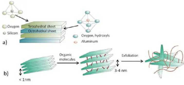
(38) Chapter I. POROUS MATERIALS. Figure 1.13 Zeolites topology: (a) possible forms of shared tetrahedra composing the framework, and examples of ( b) high Si/Al ratio zeolites and (c) low Si/Al ra tio zeolites. 1.4.3.2 Clay minerals Clay. minerals are. crystalline. aluminophyllosilicates,. divided in to. kaolinite,. montmorillonite-smectite and illite main groups. Basic building blocks of clay minerals are SiO4 silica tetraheda linked to gether to fo rm sheets. The tetr ahedral sheets are co mbined with octahedral sheet s containing Al+3, and som etimes other cations, surro unded by 6 oxygens or hydroxyls neig hbors (Fig. 1.14a). Clays are microporous materials, in which water and or ganic molecules can enter into the in terlayer regio n leading to the swelling phenomena and resulting in an enlarg ed in terlayer space (Fig. 1.14b). Expanded clay minerals facilitate easier infiltration of compounds into the clay interlayer space. The final structure is exfoliated clays. Kaoline clays are applied in the paper, ceramic, paint, plastic, rubber and cracking catalyst industries. Other clays such as sepiolite are used as adsorbents in pet litter, agricultural chemicals, water and oil sorption, pharmaceuticals, etc [59].. 23.
(39) Chapter I. POROUS MATERIALS. Figure 1.14 Schematic representation of: a) tetrahedral and octahedral sheets conforming the clay structure, and b) swelling and exfoliation of the clay structure.. 1.4.4 Meso-macroporous minerals Porous in organic materials hav ing meso- and ma cropores are found i n th e nature mainly in the form of minerals. In their chemical composition, SiO2 is combined with other oxides such as Al2O3, FeO, Na 2O, etc. Examples of such porous minerals are vermiculite, diatomaceous earth, bentonite, kao linite and perli te [60]. There is a wid e rang e of applications for th ese ma terials. For in stance, b entonite is widely applied as a binder for iron and stee l foundries, in th e purification of wine and as an adsorbent of oi ls [61]. Diatomaceous earth is exten sively app lied as a filter aid, adsorbent, in sulating material, catalyst support or carrier and natural insectide [62]. Expanded perlite is a very lightweight material applied in the construction industry, as a rooting medium and soil conditioner in horticulture, as an adsorbent in th e chemical in dustry an d as a filler in m iscellaneous processes [63].. 24.
(40) Chapter I. POROUS MATERIALS. 1..5 ORGANIC-INORGANIC POROUS MATERIALS The combination of inorganic and organic properties in a single material is attractive for the development of materials with new fu nctionalities. These fu nctionalities can be introduced in a single step during the synthesis of the porous material (direct synthesys) or by post-functionalization of the already synthesized porous material. 1.5.1 Direct synthesis Representative porous materials prepared through the direct synthesis method are metal organic frameworks and periodic mesoporous organosilicas. 1.5.1.2 Metal Organic Frameworks Metal organic fra meworks (MOFs) are highly crystallin e compounds con sisting of metal ions or clusters coordinated with rigid organic molecules to form one-, two- or threedimensional structures [64]. Fig. 1.15 illustrates examples of 2D and 3D MOFs.. Figure 1.15 Representation of MOF structures: (a) 2-D layered, and (b) 3-D.. The choice of metal and l inker dictates the structure and , hence, th e properties of the MOF. MOFs di splay an extraordinary compositional and structu ral variety with well defined pores and channels. The pore size within the framework of a MOF is typically less than 2 nm . High in ternal surface area is on e of the fo remost attributes of MOFs. The highest experimental surface area for a MOF reported to date is 7000 m2 g-1 and it has been 25.
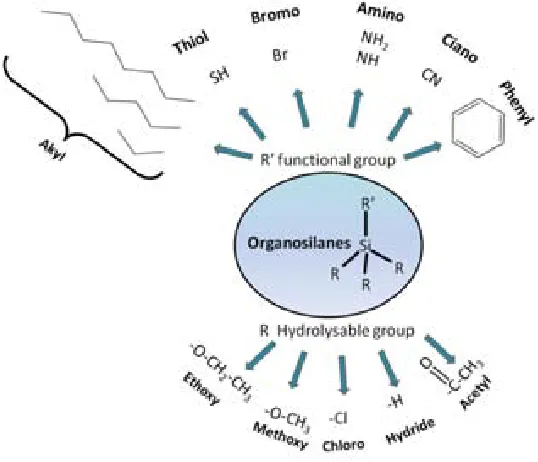
(41) Chapter I. POROUS MATERIALS. demonstrated computationally that the theoretical upper limit for MOF surface areas is ca. 14600 m2 g-1 [65]. MOFs are prepared by reacting metal ions with an organic ligand, using standard coordination chemistry methods, through hydrothermal or solvothermal techniques. Maximization of surface area is a key to the optimization of MOFs for many applications. Careful post-processing with supercritical carbon dioxide leads to substantial, or in some cases spectacular (up to 1200 %), increases in gas-accesibble surface area, due principally to solvent elimination [66]. Potential applications of MOFs are the storage of fuels and gases such as hydrogen, methane, carbon dioxide and oxygen, and in heterogeneous catalysis [67]. 1.5.1.3 Organically modified silica Trialkoxyorganosilanes of the type (RO)3SiR’, containing the R' functional group, can be incorporated during the sol-gel process of silica formation, consequently being the functionality R' projected into the pores. Through this co-condensation method, it is possible to obtain organically modified silica gels (ormosils) [68] and functionalized aerogels [69]. On a similar way, periodic mesoporous organosilicas can be obtained if tryalkoxysilanes are introduced during the condensation step around the micelle template [70]. The wide range of molecules that can be introduced allows the control of the charge, functionality, reactivity and stability of the porous material. 1.5.2 Post-synthesis functionalization: silanization A simple and cost-effective way of regularly organize chemical entities on surfaces is represented by self-assembly [71]. One of the most successful self-assembly approach is the chemical grafting of organosilanes on hydrated surfaces (silanization). Silanol groups from the internal surface of porous silica are the reactive sites where the molecules are anchored via covalent or hydrogen bonding. Organosilanes are chemical compounds with the general formula(OR)nSiR’4-n,where R’ represents the functional group and OR is the hydrolysable group, usually an alkoxy group, 26.
(42) Chapter I. POROUS MATERIALS. either methoxy or ethoxy. According to the number of hydrolysable groups, organosilanes can be mono-, di, or trisilanes for n=1, 2 or 3, respectively [72]. Fig. 1.16 illustrates some of the common functional and hydrolysable groups available for organosilanes.. Figure 1.16 Common hydrolysable and functional R groups in organosilanes.. In the silanizatio n process, th e actual bo ttom-up ma ss-production m ethods in volve techniques such as gase ous deposition for high vapor pr essure silanes, and. liquid. chemisorption, where the self -assembled monolayer is spontaneously formed by t he immersion of th e substrate in to a water-diluted alcoholic silane solu tion [73, 74]. In th e liquid aproach, the silanization mechanism can be divided into two steps (Fig. 1.17): Step 1. Hydrolysis of the alkoxy group: the initiation of the silanization occurs by the hydrolysis of one or more alkoxy group(s) pr omoted by water molecules (Fig. 1.17a), either added to the reaction medium or present as a moisture adsorbed on the pores of the inorganic substrate. Alkyl groups are released in the form of an alcohol (R-OH). Step 2. Condensation: the hydrolyzed organosilane is now susce ptible to react with other silane molecules and with the si lanol groups from the sili ca surface, establishing 27.
(43) Chapter I. POROUS MATERIALS. siloxane linkages (Si-O-Si). Both siloxane bonds and hydrogen bonding with the silanol groups on the silica surface are possible reactions (Fig 1.17b).. Figure 1 .17 Mechanism of silanization: (a ) hydrolysis of the al koxy groups in the organosilane, an d (b) condensation between org anosilane molecules and with the surface silanols forming a self-assembled structure.. The chemical gr afting of organosilane allows to attain high fu nctionalization deg rees and well -ordered monolayers without altering the po rous structure of the origin al silica [75]. Disadvantages of the liquid chemisorption route are related to the need of applying a large volume of water and organic sol vents. Moreover, applying th is route the re may be undesired side reactions, such a s excessive cross-linking of hydrolyzed organosilane molecules in solution (Fig. 1.18a), multilayer deposition on the silica surface, non-uniform surface coverage due to vertical polymerization (Fig. 1.18b) and pore-blocking [76-80].. Figure 1 .18 Side reactions of the sila nization proc ess using conve ntional liquid solvents.. 28.
(44) Chapter I. POROUS MATERIALS. In order to avoid such problems, liquid solvents can be substituted by supercritical carbon dioxide as the solvent media. Supercritical carbon dioxide has been demonstrated as an efficient technology for the silanization of silica substrates [79, 81-87]. 1.6 POROUS MATERIALS USED IN THIS WORK Ten different silicium-based materials are scrutinized in this work. All of them satisfy the key attributes required for inorganic supports to be used as solid sorbents: inertness, robustness over a wide range of pressure and temperature and easiness of functionalization. Some important characteristics of the processed matrices are shown in Table 1.1, whereas Table 1.2 summarizes the textural properties. Studied materials belong to very diverse groups of porous solids: i. Mesoporous silica gels: silica blue, clean cat and silica gel 40. ii. Ordered mesoporous silica: MCM-41. iii. Microporous aluminosilicates: zeolite Y. iv. Microporous aerogel-like particles: silica and a composite magnetite/silica. Table 1.1 Matrices classification and some important characteristics.. Type. Substrate. Mesoporous. Meso-. and. Sample. Supplier. SiO2. Particle. [wt%]. [nm]. CleanCat. CC. Iberamigo SA. >99.8. 20·105 -50·105. Silica Gel 40. SG40. Fluka. >99.8. 2·105 -5·105. MCM-41. MCM41. ACS Materials. >99.5. 200-500. Silica Blue. SB. Fluka. >99.8. 10·105 -30·105. Zeolite Y. ZY. Strem. 49. 2·104 -5·104. microporous Microporous. size. Chemicals. 29.
(45) Chapter I. POROUS MATERIALS. Table 1.2 Main textural properties of th e used substrates o btained from low temperature N2 adsorption.. Sample. Sa [m2 g-1]. Vp [cm3 g-1]. Dp [nm]. CC. 440. 0.96. 8.8. SG40. 591. 0.58. 4.1. MCM41. 1127. 0.92. 3.8. SB. 611. 0.10. 2. ZY. 739. 0.38. 1.3**. * value from MIP [88] ** Geometrical data [52]. 1.6.1 Mesoporous and meso/microporus silica gels Hydrophilic mesoporous silica gels are extremely important commercial materials (Fig. 1.20). The choice of such amorphous silica materials as important adsorbents in this thesis relies on their low cost and adsorbent properties that are suitable for a large amount of bulk applications. Amorphous silica gels CC and SG40 have a di sordered pore structu re and surface areas in the order of 400–500 m 2 g-1. Mean pore diameters are of 9 and 4 nm for CC and SG40, respectively. SB, with cobalt chloride as a humidity indicator, has a mixture of meso- and microporosity with a mean pore diameter of 2 nm and a surface area in the order of 600 m2 g-1. This material was partially dehydrated before use by heating it in an air oven at 120 ºC during 20 h. Polar silica gel substrates have a highly reactive surface with a hydroxyl surface density of 4-6 OH nm-2.. Figure 1.20 Pictures of th e silica gel s used: ( a) Clean Cat, (b) Sili ca Gel 40 and (c ) dehydrated silica blue.. 30.
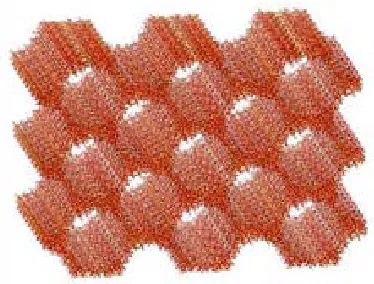
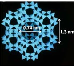
(46) Chapter I. POROUS MATERIALS. 1.6.2 Mesoporous MCM-41 MCM-41 is chosen here as the representant of th e or dered me soporous silica family, with a po re di ameter of 4 nm (Fig. 1.21). MCM -41 has a perio dic arrangement with uniform hexagonal channels running parallel in on e-dimensional non-intersecting arrays [89, 90]. This material has an extremely high mesopore volume in the order of 0.9 cm3 g-1 and a surface area of ca. 1100 m 2 g-1. The me soporous MCM -41 was bo iled in distilled water at 100 ºC for 1 h [91] previous use to increase the surface silanol density from 1 to 3 OH nm-2.. Figure 1.21 Representation of the hexagonal structure of the MCM-41.. 1.6.3 Microporous zeolite Zeolite Y, from the Fauj asite cla ss, is chosen as the microporous sub strate. It is an aluminosilicate with the chemical formula [(Ca2+,Mg2+Na+2)29(H2O)240] [Al58Si134O384] and a tridirectional ordered network of pores. This zeolite consists in almost spherical cavities of 1.3 nm in diameter accessible through tetrahedral windows of 0.74 nm (Fig. 1.23) [58]. This ze olite nust be activated before it can be used as an adso rbent. Th e activation was carried out by calcination in a tubular oven (Carbolite 3216) at 520 ºC during 48 h under a flow of nitrogen with oxygen traces. The zeolite surface area after calcination has a value of 740 m2 g-1 being the pore volume of 0.38 cm3 g-1. In a perfect zeolite crystal, the internal pore surface is electrically neu tral, and no silanols would be pr esent. Silanol groups in crystalline zeolite Y are mostly pr esent in th e external surface as t erminal groups. 31.
(47) Chapter I. POROUS MATERIALS. Experimentally, some internal silanols have been noticed and are taken as an indication of lattice defects.. Figure 1.23 Representation of the m olecular st ructure of the zeolite Y. The supercage in zeolite has a 1.3 nm dia meter accessible throu gh te trahedral windows of 0.74 nm.. 1.7 CONCLUSIONS We have presented here an overview of the most common adsorbent materials, with key characteristics, such as sy nthesis, chemical composition and poro us size. Among them, porous silica based materials were chosen in this work to modify their surface by chemical grafting with or ganic functionalities. These ma terials were chosen for several reas ons: i) their pore size varied from the micro- to the mesoporous range allows the easy insertion of organic molecules, ii) the pr esence of silano l groups in m ost of th e porous substrates allows the chemical grafting of organosilanes, iii) some of the porous substrates, such as silica gel s, are lo w cost materials and, therefore, suitable for a large a mount of bulk applications, iv) finally, the compositional and textural differences on the porous materials chosen allow to study and co mpare their in fluence on th e final properties of the or ganic modified products. Results concerning their s ynthesis pr ocess, charact erization and adsorption properties are presented and discussed in chapters III and IV.. 32.
(48) Chapter I. POROUS MATERIALS. 1.8 REFERENCES 1.. J. Rouquerol, D. Avnir, C.W. Fairbridge, D. H. Everett, J. H. Haynes, N. Pernicone, J.D. F. Ramsay, K.S.W. Swing, and K.K. Unger, Recommendations for the characterization of porous solids International Union of Pure and Applied Chemistry, 1994, 66(8), 1739.. 2.. D.H.E. K.S.W. Sing, R.A.W. Haul, L. Moscou, R.A. Pierotti, J. Rouquerol and T. Sieminiewska, , Pure and Appl. Chem., 1985, 57(4), 603.. 3.. R. Dawson, A.I. Cooper, and D.J. Adams, Nanoporous organic polymer networks. Progress in Polymer Science, 2012, 37(4), 530.. 4.. S. Polarz and B. Smarsly, Nanoporous Materials. Journal of Nanoscience and Nanotechnology, 2002, 2(6), 581.. 5.. G.L. Athens, R.M. Shayib, and B.F. Chmelka, Functionalization of mesostructured inorganic–organic and porous inorganic materials. Current Opinion in Colloid & Interface Science, 2009, 14(4), 281.. 6.. X.S. Zhao, F. Su, Q. Yan, W. Guo, X.Y. Bao, L. Lv, and Z. Zhou, Templating methods for preparation of porous structures. Journal of Materials Chemistry, 2006, 16(7), 637.. 7.. S.-Y. Ding and W. Wang, Covalent organic frameworks (COFs): from design to applications. Chemical Society Reviews, 2013, 42(2), 548.. 8.. X. Feng, X. Ding, and D. Jiang, Covalent organic frameworks. Chemical Society Reviews, 2012, 41(18), 6010.. 9.. Y. Jin, Y. Zhu, and W. Zhang, Development of organic porous materials through Schiff-base chemistry. CrystEngComm, 2013, 15(8), 1484.. 10.. A.M. Lopez-Periago, C.A. Garcia-Gonzalez, and C. Domingo, Towards the synthesis of Schiff base macrocycles under supercritical CO2 conditions. Chemical Communications, 2010, 46(24), 4315.. 11.. V.A. Davankov and M.P. Tsyurupa, Structure and properties of hypercrosslinked polystyrene—the first representative of a new class of polymer networks. Reactive Polymers, 1990, 13(1–2), 27.. 12.. S. Xu, Y. Luo, and B. Tan, Recent development of hypercrosslinked microporous organic polymers. Macromolecular Rapid Communications, 2013, 34(6), 471.. 13.. I. Pinnau and L.G. Toy, Gas and vapor transport properties of amorphous perfluorinated copolymer membranes based on 2,2-bistrifluoromethyl-4,5-difluoro-1,3-dioxole/tetrafluoroethylene. Journal of Membrane Science, 1996, 109(1), 125.. 14.. V. Abetz, Block Copolymers II, ed. V. Abetz2005: Springer.. 15.. P.M. Budd, S.M. Makhseed, B.S. Ghanem, K.J. Msayib, C.E. Tattershall, and N.B. Mckeown, Microporous polymeric materials. Materials Today, 2004, 7(4), 40.. 16.. M. Hillmyer, Nanoporous Materials from Block Copolymer Precursors, in Block Copolymers II, V. Abetz, Editor,2005, Springer Berlin Heidelberg. p. 137.. 17.. C. Khemani Kishan, Polymeric Foams: An Overview, in Polymeric Foams,1997, American Chemical Society. p. 1.. 33.
(49) Chapter I 18.. POROUS MATERIALS. L.J.M. Jacobs, M.F. Kemmere, and J.T.F. Keurentjes, Sustainable polymer foaming using high pressure carbon dioxide: a review on fundamentals, processes and applications. Green Chemistry, 2008, 10(7), 731.. 19.. I. Tsivintzelis, A.G. Angelopoulou, and C. Panayiotou, Foaming of polymers with supercritical CO2: An experimental and theoretical study. Polymer, 2007, 48(20), 5928.. 20.. A. Salerno, U. Clerici, and C. Domingo, Solid-state foaming of biodegradable polyesters by means of supercritical CO2/ethyl lactate mixtures: Towards designing advanced materials by means of sustainable processes. European Polymer Journal, 2014, 51(0), 1.. 21.. J. Lee, J. Kim, and T. Hyeon, Recent progress in the synthesis of porous carbon materials. Advanced Materials, 2006, 18(16), 2073.. 22.. R.H. Baughman, A.A. Zakhidov, and W.A. De Heer, Carbon nanotubes - The route toward applications. Science, 2002, 297(5582), 787.. 23.. R.C. Bansal; and M. Goyal, Activated Carbon Adsorption, ed. T. Francis2005: CRC Press.. 24.. John H. Knox and B. Kaur, Structure and performance of porous graphitic carbon in liquid chromatography. Journal of Chromatography A, 1986, 352, 3.. 25.. Y.H. Hu and E. Ruckenstein, Pore Size Distribution of Single-Walled Carbon Nanotubes. Industrial & Engineering Chemistry Research, 2004, 43(3), 708.. 26.. Q. Zhang, J.-Q. Huang, W.-Z. Qian, Y.-Y. Zhang, and F. Wei, The Road for Nanomaterials Industry: A Review of Carbon Nanotube Production, Post-Treatment, and Bulk Applications for Composites and Energy Storage. Small, 2013, 9(8), 1237.. 27.. R.K. Iller, The Chemistry of Silica: Solubility, Polymerization, Colloid and Surface Properties, and Biochemistry, ed. A.W.I. Publication1979.. 28.. K.K. Unver, Porous silica1979The Netherlands: Elsevier Scientific Publishing Company.. 29.. E.F. Vansant;, P.V.D. Voort;, and K.C. Vranchken, Characterization and chemical modification of the silica surface, ed. E. ScienceAmnsterdam, The Netherlands: Elsevier Science.. 30.. M. Ebelmen, Ann. Chimie Phys, 1846, 16.. 31.. T. Graham, J. Chem. Soc, 1864, 17.. 32.. J.D. Wright; and N.a.J.M. Sommerdijk, Sol-Gel Materials: Chemistry and Applications: CRC Press.. 33.. L.L. Hench and J.K. West, The sol-gel process. Chemical Reviews, 1990, 90(1), 33.. 34.. A. Soleimani Dorcheh and M.H. Abbasi, Silica aerogel; synthesis, properties and characterization. Journal of Materials Processing Technology, 2008, 199(1), 10.. 35.. L.T. Zhuravlev, The surface chemistry of amorphous silica. Zhuravlev model. Colloids and Surfaces A: Physicochemical and Engineering Aspects, 2000, 173(1-3), 1.. 36.. R. Mueller, H.K. Kammler, K. Wegner, and S.E. Pratsinis, OH Surface Density of SiO2 and TiO2 by Thermogravimetric Analysis. Langmuir, 2002, 19(1), 160.. 37.. I. Rk, The Chemistry of Silica: Solubility, Polymerization, Colloid and Surface Properties and Biochemistry, ed. Wiley1979New York Wiley.. 34.
(50) Chapter I 38.. POROUS MATERIALS. O.W. Flörke, H.A. Graetsch, F. Brunk, L. Benda, S. Paschen, H.E. Bergna, W.O. Roberts, W.A. Welsh, C. Libanati, M. Ettlinger, D. Kerner, M. Maier, W. Meon, R. Schmoll, H. Gies, and D. Schiffmann, Silica, in Ullmann's Encyclopedia of Industrial Chemistry,2000, Wiley-VCH Verlag GmbH & Co. KGaA.. 39.. H. Barthel, L. Rösch, and J. Weis, Fumed Silica - Production, Properties, and Applications, in Organosilicon Chemistry Set,2008, Wiley-VCH Verlag GmbH. p. 761.. 40.. G. Cao, Y. Lu, L. Delattre, C.J. Brinker, and G.P. López, Amorphous silica molecular sieving membranes by sol-gel processing. Advanced Materials, 1996, 8(7), 588.. 41.. G.A. Nicolaon and S.J. Teichner, Bull. Soc. Chim. Fr., 1968.. 42.. J. Fricke and T. Tillotson, Aerogels: production, characterization, and applications. Thin Solid Films, 1997, 297(1–2), 212.. 43.. N. Murillo-Cremaes, A.M. López-Periago, J. Saurina, A. Roig, and C. Domingo, Nanostructured silica-based drug delivery vehicles for hydrophobic and moisture sensitive drugs. The Journal of Supercritical Fluids, 2013, 73(0), 34.. 44.. N. Hüsing and U. Schubert, Aerogels—Airy Materials: Chemistry, Structure, and Properties. Angewandte Chemie International Edition, 1998, 37(1-2), 22.. 45.. J.S. Beck, J.C. Vartuli, W.J. Roth, M.E. Leonowicz, C.T. Kresge, K.D. Schmitt, C.T.W. Chu, D.H. Olson, and E.W. Sheppard, A new family of mesoporous molecular sieves prepared with liquid crystal templates. Journal of the American Chemical Society, 1992, 114(27), 10834.. 46.. C.T. Kresge, M.E. Leonowicz, W.J. Roth, J.C. Vartuli, and J.S. Beck, Ordered mesoporous molecular sieves synthesized by a liquid-crystal template mechanism. Nature, 1992, 359(6397), 710.. 47.. J.Y. Ying, C.P. Mehnert, and M.S. Wong, Synthesis and applications of supramolecular-templated mesoporous materials. Angewandte Chemie - International Edition, 1999, 38(1-2), 57.. 48.. Y. Belmabkhout, R. Serna-Guerrero, and A. Sayari, Adsorption of from dry gases on MCM-41 silica at ambient temperature and high pressure. 1: Pure adsorption. Chemical Engineering Science, 2009, 64(17), 3721.. 49.. C.A. Koh, T. Montanari, R.I. Nooney, S.F. Tahir, and R.E. Westacott, Experimental and computer simulation studies of the removal of carbon dioxide from mixtures with methane using AlPO4-5 and MCM-41. Langmuir, 1999, 15(18), 6043.. 50.. M. Kruk, M. Jaroniec, and A. Sayari, Adsorption study of surface and structural properties of MCM-41 materials of different pore sizes. Journal of Physical Chemistry B, 1997, 101(4), 583.. 51. 52.. W. Eytel, The physical Chemistry of the Silicates, ed. U.o.C. Press1954. Y. Ma, W. Tong, H. Zhou, and S.L. Suib, A review of zeolite-like porous materials. Microporous and Mesoporous Materials, 2000, 37(1–2), 243.. 53.. Y. Ma, W. Tong, H. Zhou, and S.L. Suib, A review of zeolite-like porous materials. Microporous and Mesoporous Materials, 2000, 37(1-2), 243.. 54.. J.E. Shelby, Introduction to Glass Science and Technology ed. T.r.S.o. Chemistry2005.. 35.
Figure
![Figure 1.5 Examples of fabrication methods for permanent porous polymers: (a) Friedel-Craft alkylation synthesis of h ypercrosslinked polystyrene [11], (b) geometrical constrains applied in the s ynthesis of Te flon AF 240 0 [13], and (c) examples of diff](https://thumb-us.123doks.com/thumbv2/123dok_es/5315767.98554/26.516.66.433.285.585/fabrication-permanent-alkylation-synthesis-ypercrosslinked-polystyrene-geometrical-constrains.webp)
+7

Documento similar
The surfaces, clay roofing tiles, with hybrid properties of superhydrophobicity and superhydrophilicity could be created by the deposition of functionalized and
The models are applied to describe experimental data derived from four different commercial Pd/Al 2 O 3 and Pd/AC catalysts for the full course of reaction and to deduce the
A histological evaluation of the surgical margins from human oral fibrous-epithelial lesions excised with CO2 laser, Diode laser, Er:YAG laser, Nd:YAG laser, electrosurgical
BACKGROUND: In this work three different techniques were applied to extract dry leaves of spinach (Spinacia oleracea): solid-liquid extraction (SLE), pressurized liquid
Heterogeneous catalysts are the most used in industry because they present several advantages such as easy post reaction separation, high
In this thesis, adsorption processes on pure silica MEL zeolite have been deeply investigated by means of a combination of experimental adsorption experiment (vol- umetric
Mazarío, “Effect of the surface charge on the adsorption capacity of chromium (VI) of iron oxide magnetic nanoparticles prepared by microwave-assisted synthesis,”.
A two-step process using supercritical fluid extraction with CO 2 has been developed to produce a low-alcohol beverage from wine that maintains the aroma and the antioxidant
