CCNP SWITCH 642-813
Quick Reference
VLAN Implementation...12
Chapter 3:
Spanning Tree...29
Chapter 4:
InterVLAN Routing ...49
Chapter 5:
Implementing High Availability...59
Chapter 6:
First Hop Redundancy ...72
Chapter 7:
Campus Network Security...79
Chapter 8:
Voice and Video
in a Campus Network ...91
Chapter 9: Wireless LANs
About the Author
Denise Donohue, CCIE No. 9566,is a senior solutions architect for ePlus Technology. She consults with companies to design updates or additions to their data and VOIP networks. Prior to this role, she was a systems engineer for the data consulting arm of SBC/AT&T. Denise has been a Cisco instructor and course director for Global Knowledge and did network consulting for many years. Her CCIE is in Routing and Switching.
About the Technical Editor
Icons Used
Router Multilayer PC
Switch Route/Switch
Processor
Campus Network Design
Chapter 1
Campus Network Design
An enterprise campus generally refers to a network in a specific geographic location. It can be within one building or span multiple buildings near each other. A campus network also includes the Ethernet LAN portions of a network outside the data center. Large enterprises have multiple campuses connected by a WAN. Using models to describe the network architecture divides the campus into several internetworking functional areas, thus simplifying design, implementation, and troubleshooting.
The Hierarchical Design Model
Cisco has used the three-level Hierarchical Design Model for years. The hierarchical design model divides a network into three layers:
n Access:Provides end-user access to the network. In the LAN, local devices such as phones and computers access
the local network. In the WAN, remote users or sites access the corporate network.
n High availability via hardware such as redundant power supplies and redundant supervisor engines. Software
redundancy via access to redundant default gateways using a first hop redundancy protocol (FHRP).
n Converged network support by providing access to IP phones, computers, and wireless access points. Provides
QoS and multicast support.
n Security through switching tools such as Dynamic ARP Inspection, DHCP snooping, BPDU Guard, port-security,
n Distribution:Aggregation point for access switches. Provides availability, QoS, fast path recovery, and load balancing.
n High availability through redundant distribution layer switches providing dual paths to the access switches and to
core switches. Use of FHRP protocols to ensure connectivity if one distribution switch is removed.
n Routing policies applied, such as route selection, filtering, and summarization. Can be default gateway for access
devices. QoS and security policies applied.
n Segmentation and isolation of workgroups and workgroup problems from the core, typically using a combination
of Layer 2 and Layer 3 switching.
n Core:The backbone that provides a high-speed, Layer 3 path between distribution layers and other network
segments. Provides reliability and scalability.
n Reliability through redundant devices, device components, and paths.
n Scalability through scalable routing protocols. Having a core layer in general aids network scalability by
provid-ing gigabit (and faster) connectivity, data and voice integration, and convergence of the LAN, WAN, and MAN.
n No policies such as ACLs or filters that would slow traffic down.
A set of distribution devices and their accompanying access layer switches are called a switch block.
The Core Layer
Is a core layer always needed? Without a core layer, the distribution switches must be fully meshed. This becomes more of a problem as a campus network grows larger. A general rule is to add a core when connecting three or more buildings or four or more pairs of building distribution switches. Some benefits of a campus core are:
n Adds a hierarchy to distribution switch connectivity
Campus Network Design
Small Campus Design
In a small campus, the core and distribution can be combined into one layer. Smallis defined as fewer than 200 end devices. In very small networks, one multilayer switch might provide the functions of all three layers. Figure 1-1 shows a sample small network with a collapsed core.
Medium Campus Design
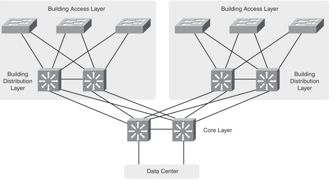
A medium-sized campus, defined as one with between 200 and 1000 end devices, is more likely to have several distribu-tion switches and thus require a core layer. Each building or floor is a campus block with access switches uplinked to redundant multilayer distribution switches. These are then uplinked to redundant core switches, as shown in Figure 1-2. FIGURE 1-1
A Small Campus Network
User Access Layer
Backbone (Collapsed Core/Distribution Layers)
Data Center Design
The core layer connects end users to the data center devices. The data center segment of a campus can vary in size from few servers connected to the same switch as users in a small campus, to a separate network with its own three-layer design in a large enterprise. The three layers of a data center model are slightly different:
n Core layer: Connects to the campus core. Provides fast switching for traffic into and out of the data center.
n Aggregation layer: Provides services such as server load balancing, content switching, SSL off-load, and security
through firewalls and IPS.
n Access layer:Provides access to the network for servers and storage units. Can be either Layer 2 or Layer 3
switches. FIGURE 1-2
A Medium-Sized Campus Network
Building Access Layer
Building Distribution
Layer
Building Access Layer
Building Distribution
Layer
Data Center
Campus Network Design
Network Traffic Flow
The need for a core layer and the devices chosen for the core also depend on the type of network traffic and traffic flow patterns. Modern converged networks include different traffic types, each with unique requirements for security, QoS, transmission capacity, and delay. These include:
n IP telephony signaling and media
n Core Application traffic, such as Enterprise Resource Programming (ERP), Customer Relationship Management
(CRM)
n Multicast multimedia
n Network management
n Application data traffic, such as web pages, email, file transfer, and database transactions
n Scavenger class traffic that requires less-than-best-effort treatment
The different types of applications also have different traffic flow patterns. These might include:
n Peer-to-Peer applications such as IP phone calls, video conferencing, file sharing, and instant messaging provides
real-time interaction. It might not traverse the core at all, if the users are local to each other. Their network require-ments vary, with voice having strict jitter needs and video conferencing using high bandwidth.
n Client-Server applications require access to servers such as email, file storage, and database servers. These servers
n Client-Enterprise Edge applications are located on servers at the WAN edge, reachable from outside the company.
These can include email and web servers, or e-commerce servers, for example. Access to these servers must be secure and highly available.
Service-Oriented Network Architecture
Service-Oriented Network Architecture (SONA) attempts to provide a design framework for a network that can deliver the services and applications businesses need. It acknowledges that the network connects all components of the business and is critical to them. The SONA model integrates network and application functionality cooperatively and enables the network to be smart about how it handles traffic to minimize the footprint of applications.
Figure 1-3 shows how SONA breaks down this functionality into three layers:
n Network Infrastructure: Campus, data center, branch, and so on. Networks and their attached end systems
(resources such as servers, clients, and storage.) These can be connected anywhere within the network. The goal is to provide anytime/any place connectivity.
n Interactive Services: Resources allocated to applications, using the network infrastructure. These include:
n Management
n Infrastructure services such as security, mobility, voice, compute, storage, and identity
n Application delivery
n Virtualization of services and network infrastructure
n Applications:Includes business policy and logic. Leverages the interactive services layer to meet business needs.
Has two sublayers:
n Application layer, which defines business applications
Campus Network Design
Planning a Network Implementation
It is important to use a structured approach to planning and implementing any network changes or new network compo-nents. A comprehensive life-cycle approach lowers the total cost of ownership, increases network availability, increases business agility, and provides faster access to applications and services.
The Prepare, Plan, Design, Implement, Operate, and Optimize (PPDIOO) Lifecycle Approach is one structure that can be used. The components are:
n Prepare:Organizational requirements gathering, high-level architecture, network strategy, business case strategy
n Plan:Network requirements gathering, network examination, gap analysis, project plan
n Design:Comprehensive, detailed design
n Implement:Detailed implementation plan, and implementation following its steps
FIGURE 1-3 The SONA Model
Infrastructure Layer
Network—Campus, Branch, Data Center, Enterprise Edge, WAN, MAN, Teleworker
Servers Clients Storage
Infrastructure Services
Layer
Application Delivery/Application-Oriented Networking
Infrastructure Services
Application Layer
Collaboration Layer
VLAN Implementation
Chapter 2
VLAN Implementation
VLANs are used to break large campus networks into smaller pieces. The benefit of this is to minimize the amount of broadcast traffic on a logical segment.
VLAN Overview
A virtual LAN (VLAN) is a logical LAN, or a logical subnet. It defines a broadcast domain. A physical subnet is a group of devices that shares the same physical wire. A logical subnet is a group of switch ports assigned to the same VLAN, regardless of their physical location in a switched network. VLAN membership can be assigned either statically by port, or dynamically by MAC address or username.
Two types of VLANs are:
n End-to-end VLAN:VLAN members reside on different switches throughout the network. They are used when hosts
are assigned to VLANs for policy reasons, rather than physical location. This provides users a consistent policy and access to resources regardless of their location. It also makes troubleshooting more complex because so many
switches can carry traffic for a specific VLAN, and broadcasts can traverse many switches. Figure 2-1 shows end-to-end VLANs.
n Local VLAN: Hosts are assigned to VLANs based on their location, such as a floor in a building.
FIGURE 2-1 End-to-End VLANs
4th Floor
HR Department
IT Department
3rd Floor
2nd Floor
1st Floor
FIGURE 2-2 Local VLANs
4th Floor
HR Department
IT Department
3rd Floor
2nd Floor
VLAN Implementation
When planning a VLAN structure, consider traffic flows and link sizing. Take into account the entire traffic pattern of applications found in your network. For instance, IP voice media traffic travels directly between phones, but signaling traffic must pass to the Unified Communications Manager. Multicast traffic must communicate back to the routing process and possibly call upon a Rendezvous Point. Various user applications, such as email and Citrix, place different demands on the network.
Application flow influences link bandwidth. Remember that uplink ports need to handle all hosts communicating concur-rently, and although VLANs logically separate traffic, traffic in different VLANs still travels over the same trunk line. Benchmark throughput for critical application and user data during peak hours; then analyze the results for any bottle-necks throughout the layered design.
User access ports are typically Fast Ethernet or faster. Access switches must have the necessary port density and can be either Layer 2 or Layer 3. Ports from user Access to the Distribution layer should be Gigabit Ethernet or better, with an oversubscription ratio of no more than 20:1. Distribution switches should be multilayer or Layer 3. Links from Distribution to the Core should be Gigabit Etherchannel or 10-Gig Ethernet, with an oversubscription of no more than 4:1.
VLAN Planning
Before beginning a VLAN implementation, you need to determine the following information:
n VLAN numbering, naming and IP addressing scheme
n VLAN placement—local or multiple switches
n Are any trunks necessary and where?
n VTP parameters
Creating a VLAN and Assigning Ports
VLANs must be created before they can be used. Creating VLANs is easy—in global configuration mode just identify the VLAN number and optionally name it!
(config)# vlan 12
(config-vlan)# name MYVLAN
Delete a VLAN by using the same command with noin front of it. There is no need to include the name when deleting.
When statically assigning ports to VLANs, first make the interface an access port, and then assign the port to a VLAN. At the interface configuration prompt:
(config-if)# switchport mode access
(config-if)# switchport access vlan 12
Verifying VLAN Configuration
To see a list of all the VLANs and the ports assigned to them, use the command show vlan. To narrow down the informa-tion displayed, you can use these keywords after the command:brief,id,vlan-number, or namevlan-name:
ASW# show vlan brief
VLAN Name Status Ports
—— ———————————————— ————- ———————————————
1 default active Fa0/1, Fa0/2, Fa0/3,
Fa0/10,Fa0/11,Fa0/12
20 VLAN0020 active Fa0/5,Fa0/6,Fa0/7
21 VLAN0021 active Fa0/8,Fa0/9
1002 fddi-default active
1003 trcrf-default active
VLAN Implementation
Other verification commands include:
n show running-config interface interface no: Use the following to verify the VLAN membership of the port:
ASW# show run interface fa0/5
Building configuration...
Current configuration 64 bytes
interface FastEthernet 0/5
switchport access vlan 20
switchport mode access
n show mac address-table interface interface-no. vlan-vlan no: Use the following to view MAC
addresses learned through that port for the specified VLAN:
ASW# show mac address-table interface fa0/1
Mac Address Table
—————————————————————
Vlan Mac Address Type Ports
—— ——— ——
——-1 0030.b656.7c3d DYNAMIC Fa0/——-1
Total Mac Addresses for this criterion: 1
n show interfaces interface-no. switchport: Use the following to see detailed information about the port
configuration, such as entries in the Administrative Mode and Access Mode VLAN fields:
ASW# show interfaces fa0/1 switchport
Name: Fa0/1
Switchport: Enabled
Administrative Mode: dynamic desirable
Operational Mode: static access
Operational Trunking Encapsulation: native
Negotiation of Trunking: On
Access Mode VLAN: 1 (default)
Trunking Native Mode VLAN: 1 (default)
Trunking VLANs Enabled: ALL
Pruning VLANs Enabled: 2-1001
Protected: false
Unknown unicast blocked: false
Unknown multicast blocked: false
Broadcast Suppression Level: 100
Multicast Suppression Level: 100
Unicast Suppression Level: 100
VLAN Trunking
A trunk is a link that carries traffic for more than one VLAN. Trunks multiplex traffic from multiple VLANs. They typically connect switches and enable ports on multiple switches to be assigned to the same VLAN.
Two methods of identifying VLANs over trunk links are:
n Inter-Switch Link (ISL):A Cisco proprietary method that encapsulates the original frame in a header, which
contains VLAN information. It is protocol-independent and can identify Cisco Discovery Protocol (CDP) and bridge protocol data unit (BPDU) frames.
n 802.1Q: Standards-based, tags the frames (inserts a field into the original frame immediately after the source MAC
address field), and supports Ethernet and Token Ring networks.
VLAN Implementation
in either the ISL encapsulation or the 802.1Q tag. The switch on the other end of the trunk removes the ISL or 802.1Q information, checks the VLAN of the frame, and adds the internal tag. If the exit port is a user port, the original frame is sent out unchanged, making the use of VLANs transparent to the user.
If a nontrunking port receives an ISL-encapsulated packet, the port cannot remove the ISL header. By default, the system installs ISL system CAM entries and drops ISL packets. In special, rare circumstances, these CAM entries are installed for every active VLAN in the switch. To prevent such collisions, enter the no-isl-entries enablecommand on switches connected to other switches. If the ISL header and footer cause the MTU size to be exceeded, it might be counted as an error.
If a nontrunking port receives an 802.1Q frame, the source and destination MAC addresses are read, the tag field is ignored, and the frame is switched normally at Layer 2.
Configuring a Trunk Link
Ports can become trunk ports either by static configuration or dynamic negotiation using Dynamic Trunking Protocol (DTP). A switch port can be in one of five DTP modes:
n Access:The port is a user port in a single VLAN.
n Trunk:The port negotiates trunking with the port on the other end of the link.
n Non-negotiate:The port is a trunk and does not do DTP negotiation with the other side of the link.
n Dynamic Desirable:Actively negotiates trunking with the other side of the link. It becomes a trunk if the port on
the other switch is set to trunk,dynamic desirable, or dynamic automode.
Configure a port for trunking at the interface configuration mode:
(config-if)#switchport mode {dynamic {auto | desirable} | trunk}
If dynamic mode is used, DTP negotiates the trunking state and encapsulation. If trunk mode is used, you must specify encapsulation, and you can disable all DTP negotiation:
(config-if)#switchport trunk encapsulation {isl | dot1q | negotiate}
(config-if)# switchport nonnegotiate
If you use 802.1Q, specify a native VLAN for the trunk link with the command:
(config-if)# switchport trunk native vlan vlan-no
Frames from the native VLAN are sent over the trunk link untagged. Native VLAN must match on both sides of the trunk link. VLAN 1 is the default native VLAN for all ports, but best practice is to set the native VLAN to one not assigned to users. This practice also decreases the danger of having a large spanning tree instance in VLAN1.
VLANs Allowed on the Trunk
By default, a trunk carries traffic for all VLANs. You can change that behavior for a particular trunk link by giving the following command at the interface config mode:
switchport trunk allowed vlan vlans
Make sure that both sides of a trunk link enable the same VLANs.
Verifying a Trunk Link
Two commands you can use to verify your trunk configuration are
VLAN Implementation
Using the trunkkeyword with the show interfacescommand gives information about the trunk link:
# show interfaces fastethernet 0/1 trunk
Port Mode Encapsulation Status Native vlan
Fa0/1 desirable n-802.1q trunking 1
Port Vlans allowed on trunk
Fa0/1 1-150
<further output omitted>
Best Practices for Trunking
n Change the Native VLAN to one not assigned to any users.
n On links that should be trunks, turn off trunking negotiation by setting the mode to trunk, specifying the
encapsula-tion type, and adding the nonnegotiatecommand.
n On links that should never be trunks, turn off trunking negotiation by setting the switchport mode to host. This sets
it as an access port, enables Portfast, and disables EtherChannel negotiation.
n Limit the VLAN traffic carried by the trunk to only those VLANs it needs to carry.
VLAN Trunking Protocol
VTP works by using Configuration Revision numbers and VTP advertisements:
n All switches send out VTP advertisements every five minutes or when there is a change to the VLAN database
(when a VLAN is created, deleted, or renamed).
n VTP advertisements contain a Configuration Revision number. This number is increased by one for every VLAN
change.
n When a switch receives a VTP advertisement, it compares the Configuration Revision number against the one in its
VLAN database.
n If the new number is higher, the switch overwrites its database with the new VLAN information and forwards the
information to its neighbor switches.
n If the number is the same, the switch ignores the advertisement.
n If the new number is lower, the switch replies with the more up-to-date information contained in its own database.
VTP Switch Roles
A switch can be a VTP:n Server:The default VTP role. Servers can create, delete, and rename VLANs. They originate both periodic and
trig-gered VTP advertisements and synchronize their databases with other switches in the domain.
n Client:Clients cannot make VLAN changes. They originate periodic VTP advertisements and synchronize their
databases with other switches in the domain.
n Transparent: It can create, delete, and rename VLANs, but its VLANs are only local. It does not originate
VLAN Implementation
The two versions of VTP are Version 1 and Version 2. To use Version 2, all switches in the domain must be capable of using it. Configure one server for Version 2, and the information is propagated through VTP. Version 2 has the following added features:
n It supports Token Ring VLANs.
n Transparent switches pass along messages from both versions of VTP.
n Consistency checks are performed only when changes are configured through the CLI or SNMP.
Configuring VTP
VTP configuration is done at the global config mode. To configure the switch’s VTP mode:
(config)# vtp {server | client |transparent}
To configure the VTP domain name:
(config)# vtp domain name
To configure a VTP password (all switches in the domain must use the same password):
(config)# vtp password password
To configure the switch to use VTP Version 2:
Verifying and Monitoring VTP
To get basic information about the VTP configuration, use show vtp status. The example shows the default settings:
# show vtp status
VTP Version : 1
Configuration Revision : 0
Maximum VLANs supported locally : 1005
Number of existing VLANs : 5
VTP Operating Mode : Server
VTP Domain Name :
(config)#
VTP Pruning Mode : Disabled
VTP V2 Mode : Disabled
VTP Traps Generation : Disabled
MD5 digest :
Adding a New Switch to a VTP Domain
Adding a new switch in client mode does not prevent it from propagating its incorrect VLAN information. A server synchronizes to a client if the client has the higher configuration revision number. You must reset the revision number back to 0 on the new switch. To be safe, follow these steps:
Step 1. With the switch disconnected from the network, set it as VTP transparent and delete the vlan.dat file from its flash memory.
Step 2. Set it to a fake VTP domain name and into client mode.
Step 3. Reboot the switch.
VLAN Implementation
EtherChannels
An EtherChannel is a way of combining several physical links between switches into one logical connection. Normally, Spanning Tree blocks redundant links; EtherChannels get around that and enable load balancing across those links. Traffic is balanced between the channel links on the basis of such things as source or destination MAC address or IP address. The EtherChannel load-balancing method is configured at global configuration mode.
(config)# port-channel load-balance type
A logical interface—called the Port Channel interface—is created. Configuration can be applied to both the logical and physical interfaces.
Some guidelines for EtherChannels follows:
n Interfaces in the channel do not have to be physically next to each other or on the same module.
n All ports must be the same speed and duplex.
n All ports in the bundle should be enabled.
n None of the bundle ports can be a SPAN port.
n Assign an IP address to the logical Port Channel interface, not the physical ones, if using a Layer 3 EtherChannel.
n Put all bundle ports in the same VLAN, or make them all trunks. If they are trunks, they must all carry the same
VLANs and use the same trunking mode.
n The configuration you apply to the Port Channel interface affects the entire EtherChannel. The configuration you
Configuring an EtherChannel
Basically, you should configure the logical interface and then put the physical interfaces into the channel group:
(config)# interface port-channel number
![any additional configuration, such as trunking for a Layer 2 EtherChannel]
For a Layer 3 EtherChannel, add the following:
(config-if)# no switchport
(config-if)# ip address address mask
Then, at each port that is part of the EtherChannel, use the following:
(config)# interface { number | range interface – interface}
(config-if)# channel-group number mode {auto | desirable | on}
Putting the IP address on the Port Channel interface creates a Layer 3 EtherChannel. Simply putting interfaces into a channel group creates a Layer 2 EtherChannel, and the logical interface is automatically created.
The Cisco proprietary Port Aggregation Protocol (PAgP) dynamically negotiates the formation of a channel. There are three PAgP modes:
n On:The port channels without using PAgP negotiation. The port on the other side must also be set to On.
n Auto: Responds to PAgP messages but does not initiate them. Port channels if the port on the other end is set to
Desirable. This is the default mode.
n Desirable:Port actively negotiates channeling status with the interface on the other end of the link. Port channels if
VLAN Implementation
Link Aggregation Control Protocol (LACP) is an IEEE standard protocol, IEEE 802.3ad, which does the same thing. LACP modes follow:
n On:The port channels without using LACP negotiation. The port on the other side must also be set to On.
n Active:Port actively negotiates channeling with the port on the other end of the link. A channel forms if the other
side is Passive or Active.
n Passive: Responds to LACP messages but does not initiate them. A channel forms only if the other end is set to
Active.
If you want to use LACP, specify it under the interface and put the interface in either active or passive mode:
(config-if)# channel-protocol lacp
(config-if) channel-group number mode {active | passive}
Verifying an EtherChannel
Some typical commands for verifying include the following:# show running-config interface number
# show interfaces number etherchannel
# show etherchannel number port-channel
# show etherchannel summary
Troubleshooting VLAN Issues
Configuration problems can arise when user traffic must traverse several switches. The following sections list some common configuration errors. But before you begin troubleshooting, create a plan. Check the implementation plan for any changes recently made, and determine likely problem areas.
Troubleshooting User Connectivity
User connectivity can be affected by several things:n Physical connectivity: Make sure the cable, network adapter, and switch port are good. Check the port’s link LED.
n Switch configuration: If you see FCS errors or late collisions, suspect a duplex mismatch. Check configured speed
on both sides of the link. Make sure the port is enabled and set as an access port.
n VLAN configuration: Make sure the hosts are in the correct VLAN.
n Allowed VLANs:Make sure that the user VLAN is allowed on all appropriate trunk links.
Troubleshooting Trunking
When troubleshooting trunking, make sure that physical layer connectivity is present before moving on to search for configuration problems such as
n Are both sides of the link in the correct trunking mode?
n Is the same trunk encapsulation on both sides?
n If 802.1Q, is the same native VLAN on both sides? Look for CDP messages warning of this error.
VLAN Implementation
Troubleshooting VTP
The following are some common things to check when troubleshooting problems with VTP:
n Make sure you are trunking between the switches. VTP is sent only over trunk links.
n Make sure the domain name matches on both switches. (The name is case sensitive.)
n If the switch is not updating its database, make sure it is not in transparent mode.
n If using passwords, make sure they all match. To remove a password, use no vtp password.
n If VLANs are missing, check the Revision number for a possible database overwrite. Also check the number of
Chapter 3
Spanning Tree
Ethernet network design balances two separate imperatives. First, Ethernet has no capacity for detecting circular paths. If such paths exist, traffic loops around and accumulates until new traffic is shut out. (This is called a broadcast storm.) Second, having secondary paths is good preparation for inevitable link failure.
Spanning Tree is a protocol that prevents loop formation by detecting redundant links and disabling them until needed. Designers can therefore build redundant links, and the protocol enables one to pass traffic and keep the other in reserve. When the active link fails, the secondary link is enabled quickly.
Understanding the Spanning Tree Protocol
Switches either forward or filter Layer 2 frames. The way they make the forwarding/filtering decision can lead to loops in a network with redundant links. Spanning Tree is a protocol that detects potential loops and breaks them.
A Layer 2 switch is functionally the same thing as a transparent bridge. Transparent bridges:
n Learn MAC (Media Access Control) addresses by looking at the source address of incoming frames. They build a
table mapping MAC address to port number.
n Forward broadcasts and multicasts out all ports except the one in which they came. (This is called flooding.)
n Forward unknown unicasts out all ports except the one in which they came. An unknown unicast is a message bound
for a unicast MAC address that is not in the switch’s table of addresses and ports.
Spanning Tree
Spanning Tree Protocol (STP) works by selecting a root bridge and then selecting one loop-free path from the root bridge to every other switch. (STP uses the term bridgebecause it was written before there were switches.) Consider the follow-ing switched network (see Figure 3-1).
Spanning Tree must select
n One root bridge
n One root port per nonroot bridge
n One designated port per network segment
Spanning Tree Election Criteria
Spanning Tree builds paths out from a central point along the fastest available links. It selects paths according to the following criteria:
n Lowest root bridge ID (BID)
n Lowest path cost to the root
n Lowest sender bridge ID
n Lowest sender port ID (PID)
When reading the path selection criteria, remember the following:
n Bridge ID:Bridge priority: Bridge MAC address.
n Bridge priority:2-btye value, 0–65,535 (0–0xFFFF).
n Default priority:32,768 (0x8000).
n Port ID:Port priority: port number.
n Port priority:A 6-bit value, 0–63, default is 32.
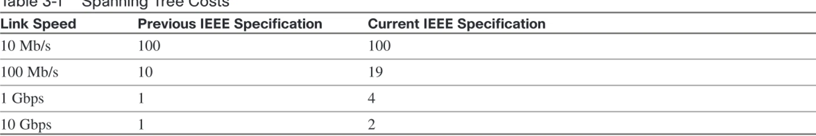
n Path cost:This is the cumulative value of the cost of each link between the bridge and the root. Cost values were
Spanning Tree
Table 3-1 Spanning Tree Costs
Link Speed Previous IEEE Specification Current IEEE Specification
10 Mb/s 100 100
100 Mb/s 10 19
1 Gbps 1 4
10 Gbps 1 2
The STP Election
Spanning Tree builds paths out from a starting point, the “root” of the tree. The first step in selecting paths is to identify this root device. Then each device selects its best path back to the root, according to the criteria laid out in the previous sections (lowest root BID, lowest cost, lowest advertising BID, lowest port ID).
Root Bridge Election
Looking at Figure 3-1, first select the root bridge. Assume each switch uses the default priority.
n Switch A BID = 80–00–00–0c-11–11–00–11
n Switch B BID = 80–00–00–0c–26–78–10–10
n Switch C BID = 80–00–00–0c-32–1a-bc-de
n Switch D BID = 80–00–00–0c-81–81–11–22
n Switch E BID = 80–00–00–0c–26–79–22–22
Root Port Election
The root port is the port that leads back to the root. Continuing with Figure 3-1, when A is acknowledged as the root, the remaining bridges sort out their lowest cost path back to the A:
n Switch B:Uses the link to A with a cost of 19 (link speed of 100 Mb/s).
n Switch C:The connected link has a cost of 100 (Ethernet), the link through B has a path cost of 38 (two 100-Mb/s
links), and so B is chosen.
n Switch D:The link through B has a path cost of 119, the path cost through C to A is 119, the path through C then B
is 57, so C is chosen.
n Switch E:The lowest path cost is the same for both ports (76 through D to C to B to A). Next check sender BID—
sender for both ports is D so that it does not break the tie. Next check sender Port ID. Assuming default port priority, the PID for 0/1 is lower than the PID for 0/2, so the port on the left is the root port.
Designated Port Election
Designated ports are ports that lead away from the root. Obviously, all ports on the root bridge are designated ports (A–B and A–C in Figure 3-1).
n Segment B–D:B has the lowest path cost to root (19 versus 119), so it is designated for this segment.
n Segment C–D:C has the lowest path cost to the root (100 versus 119), so it is designated for this segment.
n Segment B–C:B has the lowest path cost to the root (19 versus 100), so it is designated for this segment.
n Both segments D–E:D has the lowest cost to the root (57 versus 76), so it is designated for both segments.
Spanning Tree
Bridge Protocol Data Units
Switches exchange Bridge Protocol Data Units (BPDU). The two types of BPDUs are Configuration and Topology Change Notification(TCN). Configuration BPDUs are sent every two seconds from the root toward the downstream switches. They:
n Are used during an election
n Maintain connectivity between switches
n Send timer information from the root
FIGURE 3-2 The Active Topology After Spanning Tree Is Complete
A
BC
D
TCN BPDUs are sent by a downstream switch toward the root when:
n There is a link failure.
n A port starts forwarding, and there is already a designated port.
n The switch receives a TCN from a neighbor.
When a switch receives a TCN BPDU, it acknowledges that with a configuration BPDU that has the TCN Acknowledgment bit set.
When the root bridge receives a TCN, it starts sending configuration BPDUs with the TCN bit set for a period of time equal to max age plus forward delay. Switches that receive this change their MAC table aging time to the Forward Delay time, causing MAC addresses to age faster. The topology change also causes an election of the root bridge, root ports, and designated ports.
Some of the fields in the BPDU include:
n Root bridge ID:The BID of the current root
n Sender’s root path cost:The cost to the root
n Sender’s bridge ID: Sender’s priority concatenated to MAC
n Sender’s port ID:The port number, transmitted as final tie-breaker
n Hello time:Two seconds by default
n Forward Delay: Fifteen seconds by default
Spanning Tree
Spanning Tree Port States
When a port is first activated, it transitions through the following stages shown in Table 3-2.
Table 3-2 Spanning Tree Port States
Port State Timer Action
Blocking Max Age (20 sec) Discards frames, does not learn MAC addresses, receives BPDUs
Listening Forward Delay (15 sec) Discards frames, does not learn MAC addresses, receives BPDUs to determine its role in the network
Learning Forward Delay (15 sec) Discards frames, does learn MAC addresses, receives and transmits BPDUs
Forwarding Accepts frames, learns MAC addresses, receives and transmits BPDUs
Per-VLAN Spanning-Tree
The IEEE’s version of STP assumes one common Spanning-tree instance (and thus one root bridge) regardless of how many VLANs are configured. With the Cisco Per-VLAN Spanning-Tree (PVST+) there is a different instance of STP for each VLAN. To derive the VLAN BID, the switch picks a different MAC address from its base pool for each VLAN. Each VLAN has its own root bridge, root port, and so on. You can configure these so that data flow is optimized, and traffic load is balanced among the switches by configuring different root bridges for groups of VLANs.
Configuring Spanning Tree
To change the STP priority value, use the following:
Switch (config)# spanning-tree vlan vlan_no. priority value
To configure a switch as root without manually changing priority values, use the following:
Switch (config)# spanning-tree vlan vlan_no. root {primary | secondary}
To change the STP port cost for an access port, use the following:
Switch(config-if)# spanning-tree cost value
To change the STP port cost for a VLAN on a trunk port, use the following:
Switch(config-if)# spanning-tree vlan vlan_no. cost value
To display STP information for a VLAN, use the following:
Switch# show spanning-tree vlan vlan_no.
To display the STP information for an interface, use the following:
Switch # show spanning-tree interface interface_no. [detail]
To verify STP timers, use the following:
Spanning Tree
Portfast
Portfast is a Cisco-proprietary enhancement to Spanning Tree that helps speed up network convergence. It is for access (user) ports only. Portfast causes the port to transition directly to forwarding, bypassing the other STP states. Connecting a switch to a Portfast port can cause loops to develop. Configure Portfast on an interface or interface range:
(config-if)# spanning-tree portfast
It can also be configured globally:
(config)# spanning-tree portfast default
Rapid Spanning Tree
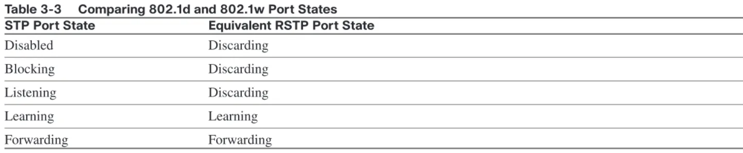
Rapid Spanning Tree (RSTP) 802.1w is a standards-based, nonproprietary way of speeding STP convergence. Switch ports exchange an explicit handshake when they transition to forwarding. RSTP describes different port states than regular STP, as shown in Table 3-3.
Table 3-3 Comparing 802.1d and 802.1w Port States STP Port State Equivalent RSTP Port State
Disabled Discarding
Blocking Discarding
Listening Discarding
Learning Learning
RSTP Port Roles
RSTP also defines different Spanning Tree roles for ports:
n Root port:The best path to the root (same as STP)
n Designated port:Same role as with STP
n Alternate port:A backup to the root port
n Backup port:A backup to the designated port
n Disabled port:Not used in the Spanning Tree
n Edge port:Connected only to an end user
BPDU Differences in RSTP
In regular STP, BPDUs are originated by the root and relayed by each switch. In RSTP, each switch originates BPDUs, whether or not it receives a BPDU on its root port. All eight bits of the BPDU type field are used by RSTP. The TC and TC Ack bits are still used. The other six bits specify the port’s role and its RSTP state and are used in the port handshake. The RSTP BPDU is set to Type 2, Version 2. PVST is done by Rapid PVST+ on Catalyst switches.
RSTP Fast Convergence
The Rapid Spanning Tree process understands and incorporates topology changes much quicker than the previous version:
n RSTP uses a mechanism similar to BackboneFast:When an inferior BPDU is received, the switch accepts it. If
the switch has another path to the root, it uses that and informs its downstream switch of the alternative path.
Spanning Tree
n Link type:If you connect two switches through a point-to-point link and the local port becomes a designated port, it
exchanges a handshake with the other port to quickly transition to forwarding. Full-duplex links are assumed to be point-to-point; half-duplex links are assumed to be shared.
n Backup and alternate ports:Ports that can transition to forwarding when no BPDUs are received from a neighbor
switch (similar to UplinkFast).
If an RSTP switch detects a topology change, it sets a TC timer to twice the hello time and sets the TC bit on all BPDUs sent out its designated and root ports until the timer expires. It also clears the MAC addresses learned on these ports. Only changes to the status of non-Edge ports cause a TC notification.
If an RSTP switch receives a TC BPDU, it clears the MAC addresses on that port and sets the TC bit on all BPDUs sent out its designated and root ports until the TC timer expires. Enable and verify Rapid STP with the commands:
Switch(config)# spanning-tree mode rapid-pvst
Switch# show spanning-tree
A version of PVST+ is used with Rapid Spanning Tree, called Per-VLAN Rapid Spanning Tree (PVRST+). You should still configure root and secondary root bridges for each VLAN when using RSTP.
Multiple Spanning Tree
With Multiple Spanning Tree (MST), you can group VLANs and run one instance of Spanning Tree for a group of VLANs. This cuts down on the number of root bridges, root ports, designated ports, and BPDUs in your network. Switches in the same MST Region share the same configuration and VLAN mappings. Configure and verify MST with these commands:
(config)# spanning-tree mode mst
(config-mst)# revision number
(config-mst)# instance number vlan vlan_range
(config-mst)# end
# show spanning-tree mst
To be compatible with 802.1Q trunking, which has one common Spanning Tree (CST) for all VLANs, MST runs one instance of an Internal Spanning Tree (IST). The IST appears as one bridge to a CST area and is MST instance number 0. The original MST Spanning Trees (called M-Trees) are active only in the region; they combine at the edge of the CST area to form one.
Spanning Tree Stability Mechanisms
Spanning Tree has several additional tools for tuning STP to protect the network and keep it operating properly. They include:
n PortFast (discussed previously)
n UplinkFast
n BackboneFast
n BPDU Guard
n BPDU Filtering
n Root Guard
n UDLD
Spanning Tree
UplinkFast
UplinkFast is for speeding convergence when a direct link to an upstream switch fails. The switch identifies backup ports for the root port. (These are called an uplink group.) If the root port fails, one of the ports in the uplink group is
unblocked and transitions immediately to forwarding; it bypasses the listening and learning stages. It should be used in wiring closet switches with at least one blocked port.
The command to enable uplinkfast is shown next. Please note that uplinkfast is enabled globally, so the command affects all ports and all VLANs.
(config)# spanning-tree uplinkfast
BackboneFast
BackboneFast is used for speeding convergence when a link fails that is not directly connected to the switch. It helps the switch detect indirect failures. If a switch running BackboneFast receives an inferior BPDU from its designated bridge, it knows a link on the path to the root has failed. (An inferior BPDU is one that lists the same switch for the root bridge and designated bridge.)
The switch then tries to find an alternate path to the root by sending a Root Link Query (RLQ) frame out all alternate ports. The root then responds with an RLQ response, and the port receiving this response can transition to forwarding. Alternate ports are determined in this way:
n If the inferior BPDU was received on a blocked port, the root port and any other blocked ports are considered alternates.
n If the inferior BPDU was received on the root port, all blocked ports are considered alternates.
n If the inferior BPDU was received on the root port and there are no blocked ports, the switch assumes it has lost
Configure this command on all switches in the network:
(config)# spanning-tree backbonefast
BPDU Guard
BPDU Guard prevents loops if another switch is attached to a Portfast port. When BPDU Guard is enabled on an inter-face, it is put into an error-disabled state (basically, shut down) if a BPDU is received on the interface. It can be enabled at either global config mode—in which case it affects all Portfast interfaces—or at interface mode. Portfast does not need to be enabled for it to be configured at a specific interface. The following configuration example shows BPDU guard being enabled and verified.
(config)# spanning-tree portfast bpduguard default
(config-if)# spanning-tree bpduguard enable
# show spanning-tree summary totals
BPDU Filtering
BPDU filtering is another way of preventing loops in the network. It also can be enabled either globally or at the interface and functions differently at each. In global config, if a Portfast interface receives any BPDUs, it is taken out of Portfast status. At interface config mode, it prevents the port from sending or receiving BPDUs. The commands are:
(config)# spanning-tree portfast bpdufilter default
Spanning Tree
Root Guard
Root Guard is meant to prevent the wrong switch from becoming the Spanning Tree root. It is enabled on ports other than the root port and on switches other than the root. If a Root Guard port receives a BPDU that might cause it to become a root port, the port is put into “root-inconsistent” state and does not pass traffic through it. If the port stops receiving these BPDUs, it automatically reenables itself. To enable and verify Root Guard use the following commands:
(config-if)# spanning-tree guard root
# show spanning-tree inconsistentports
Unidirectional Link Detection
A switch notices when a physical connection is broken by the absence of Layer 1 electrical keepalives. (Ethernet calls this a link beat.) However, sometimes a cable is intact enough to maintain keepalives but not to pass data in both direc-tions. This is a Unidirectional Link. Operating at Layer 2, Unidirectional Link Detection (UDLD) detects a unidirectional link by sending periodic hellos out to the interface. It also uses probes, which must be acknowledged by the device on the other end of the link.
UDLD has two modes: normal and aggressive. In normal mode, the link status is changed to Undetermined State if the hellos are not returned. In aggressive mode, the port is error-disabled if a unidirectional link is found. Aggressive mode is the recommended way to configure UDLD.
To enable UDLD on all fiber-optic interfaces, use the following command:
(config)# udld [enable | aggressive]
Although this command is given at global config mode, it applies only to fiber ports.
To control UDLD on a specific fiber port, use the following command:
(config-if)# udld port {aggressive | disable}
To reenable all interfaces shut by UDLD, use the following:
# udld reset
To verify UDLD status, use the following:
# show udld interface
Loop Guard
Loop Guard prevents loops that might develop if a port that should be blocking inadvertently transitions to the forwarding state. This can happen if the port stops receiving BPDUs (perhaps because of a unidirectional link or a software/configu-ration problem in its neighbor switch). When one of the ports in a physically redundant topology stops receiving BPDUs, the STP conceives the topology as loop-free. Eventually, the blocking port becomes designated and moves to forwarding state, thus creating a loop. With Loop Guard enabled, an additional check is made.
If no BPDUs are received on a blocked port for a specific length of time, Loop Guard puts that port into “loop inconsis-tent” blocking state, rather than transitioning to forwarding state. Loop Guard should be enabled on all switch ports that have a chance of becoming root or designated ports. It is most effective when enabled in the entire switched network in conjunction with UDLD.
To enable Loop Guard for all point-to-point links on the switch, use the following command:
Spanning Tree
To enable Loop Guard on a specific interface, use the following:
(config-if)# spanning-tree guard loop
Loop Guard automatically reenables the port if it starts receiving BPDUs again.
Troubleshooting STP
Some common things to look for when troubleshooting Spanning Tree Protocol include:
n Duplex mismatch:When one side of a link is half-duplex and the other is full-duplex. This causes late collisions
and FCS errors.
n Unidirectional link failure:The link is up but data flows only in one direction. It can cause loops.
n Frame corruption:Physical errors on the line cause BPDUs to be lost, and the port incorrectly begins forwarding.
This is caused by duplex mismatch, bad cable, or cable too long.
n Resource errors: STP is implemented in software, so a switch with an overloaded CPU or memory might neglect
some STP duties.
n Port Fast configuration errors: Connecting a switch to two ports that have Port Fast enabled. This can cause a
loop.
n STP tuning errors:Max age or forward delay set too short can cause a loop. A network diameter that is set too low
Identifying a Bridging Loop
Suspect a loop if you see the following:n You capture traffic on a link and see the same frames multiple times.
n All users in a bridging domain have connectivity problems at the same time.
n There is abnormally high port utilization.
To remedy a loop quickly, shut redundant ports and then enable them one at a time. Some switches enable debugging of STP to help in diagnosing problems. The following commands are useful for isolating a bridging loop:
show interfaces
show spanning tree
show bridge
show process cpu
debug spanning tree
show mac address-table aging-time vlan#
show spanning-tree vlanvlan#detail
Spanning-Tree Best Practices
To optimize data flow in the network, design and configure Spanning Tree in the following ways:
n Statically configure switches to be the primary and secondary root bridges by setting priority values.
Spanning Tree
n Tune STP using the tools detailed in this section.
n Enable UDLD aggressive mode on all fiber interfaces.
n Design STP domains that are as simple and contained as possible by using multilayer switches and routed links.
n Use PVRST+ or MST for the fastest convergence times.
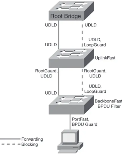
Confused by all the acronyms and STP features? Figure 3-3 shows the STP tools you might use in your network and where you might use them.
FIGURE 3-3 Example Switched Topology
Root Bridge
UDLD
UDLD
UDLD
UDLD, LoopGuard
RootGuard, UDLD
RootGuard, UDLD
UDLD
UDLD, LoopGuard
BackboneFast, BPDU Filter
PortFast, BPDU Guard
Forwarding Blocking
Chapter 4
InterVLAN Routing
VLANs divide the network into smaller broadcast domains but also prohibit communication between domains. To enable communication between those groups–without also passing broadcasts–routing is used.
InterVLAN Routing Using an External Router
A Layer 2 switch can connect to a router to provide reachability between VLANs. This can be done either via separate physical links for each VLAN or via a trunk link from the switch to the router. A trunk link is most common and this type of setup is frequently called Router on a Stick.
When using a trunk link you must create separate subinterfaces on the router’s physical interface—one subinterface for each VLAN plus one for the native VLAN. This can work with any kind of switch and the implementation is straightfor-ward, but the router becomes a single point of failure for all users, and the trunk link might become congested.
The router’s configuration would look similar to the following:
interface FastEthernet0/1
no ip address
duplex auto
speed auto
!
interface FastEthernet0/1.20
InterVLAN Routing
encapsulation dot1Q 20
ip address 10.1.20.1 255.255.255.0
!
interface FastEthernet0/1.99
description Native VLAN
encapsulation dot1Q 99 native
ip address 10.1.99.1 255.255.255.0
!
interface FastEthernet0/1.120
description Data VLAN
encapsulation dot1Q 120
ip address 10.1.120.1 255.255.255.0
InterVLAN Routing Using Multilayer Switches
A multilayer switch can do both Layer 2 switching and Layer 3 routing between VLANs. This section walks you through the switching process and focuses on order of operations. The order in which things happen is extremely important for two reasons. First, the order of events is good test material. Second, understanding the processing order allows you to evaluate how the various filtering and forwarding mechanisms interact. (Examples include error checking, access-lists, VLAN access-lists, routing, and QoS.)
The Layer 2 and Layer 3 Forwarding Process
Input
1. Receive frame
2. Verify frame integrity
3. Apply inbound VLAN ACL (VLAN Access Control List)
4. Look up destination MAC (Media Address Code)
Output
1. Apply outbound VLAN ACL
2. Apply outbound QoS ACL
3. Select output port
4. Place in port queue
5. Rewrite
6. Forward
A multilayer switch does Layer 3 forwarding when the destination MAC address is one of the switch’s own addresses. The steps involved in Layer 3 forwarding are as follows:
Input
1. Receive frame.
2. Verify frame integrity.
3. Apply inbound VLAN ACL.
InterVLAN Routing
Routing
1. Apply input ACL
2. Switch if entry is in CEF cache
3. Identify exit interface and next-hop address using routing table
4. Apply output ACL
Output
1. Apply outbound VLAN ACL.
2. Apply outbound QoS ACL.
3. Select output port.
4. Place in interface queue.
5. Rewrite source and destination MAC, IP checksum and frame check sequence, and decrement TTL (Time to Live field in the IP header).
6. Forward.
Understanding the Switching Table
In comparison, Multilayer Switching (MLS) uses aa Ternary Content Addressable Memory (TCAM) table to store infor-mation needed by Layer 3 and higher processing. This might include QoS and ACLs. Values in the TCAM table include ternary values (0, 1, or wildcard). An exact match is not required—the longest match is considered a hit.
MLS Interfaces
A multilayer switch can have the following types of interfaces:
n Layer 2 Interface:Either an access port assigned to a VLAN or a trunk port.
n Switch Virtual Interface (SVI):A virtual, software interface for the VLAN itself. Can be either a Layer 2 interface
or a Layer 3 interface.
n Routed Interface:A physical interface that is not associated with a VLAN and acts like a router port.
SVI Configuration
A default SVI for VLAN 1 is automatically created in the switch. To create an SVI use the command interface vlan#. Configure an IP address on the SVI to make it a Layer 3 interface. SVIs are used to:
n Route or fallback bridge between VLANs.
n Provide a default gateway for users in that VLAN.
n Route traffic into or out of its associated VLAN.
n Provide an IP address for connectivity to the switch itself.
InterVLAN Routing
An SVI is considered “up” as long as at least one port in its associated VLAN is active and forwarding. If all ports in the VLAN are down, the interface goes down to avoid creating a routing black hole. You might not want the status of a particular port (one not connected to a host) to affect the SVI’s status. Some Cisco switches enable you to use the follow-ing command on that interface.
Switch(config-if)# switchport autostate exclude
To configure InterVLAN routing using a Layer 3 SVI, you need to:
n Enable IP routing.
n Create the VLANs.
n Create the SVIs.
n Associate an IP address with each SVI.
n Configure a dynamic routing protocol if needed.
Switch(config)#ip routing
Switch(config)# vlan 3
Switch(config)# interface vlan 3
Switch(config-if)#ip address 10.3.3.3 255.255.255.0
Routed Switch Port Configuration
To configure an interface as a routed port, you must remove the Layer 2 functionality with the no switchport interface command. Then you can add an IP address and configure routing as needed:
sw1(config)# int fa 1/0/5
sw1(config-if)# no switchport
To verify your configuration, use the commands show ip interface brief,show interface, or show running-config inter-faceint-#.
Understanding Switch Forwarding Architectures
Packets entering a router or multilayer switch are handled by one of three types of switching:
n Process Switching:Each packet must be examined by the CPU and handled in software. Slowest method, used in
routers only.
n Fast Switching: CPU process switches the first packet in each flow, then caches that information, and switches
subsequent packets in hardware. Faster than process switching, used in routers and multilayer switches. Also called route caching.
n Cisco Express Forwarding (CEF):A table is prebuilt with adjacency information for all destinations in the routing
table. Fastest method, is the default for Cisco routers and multilayer switches. Also called topology-based switching.
CEF Switching
InterVLAN Routing
n Separates control plane hardware from data plane hardware.
n Controls plane runs in software and builds FIB and adjacency table.
n The data plane uses hardware to forward most IP unicast traffic.
n Uses TCAM table.
n Can be centralized or distributed.
Not all types of traffic can be handled by CEF. Some types that are punted (sent to the processor for handling) are:
n Packets with IP header options
FIGURE 4-1 Cisco Express Forwarding
BGP Table
Address Prefix AS-Path Next-Hop Communities Other Attr. 10.0.0.0 /8 42 13 1.2.3.4 37:12
... ... ... ... ... ... IP Routing Table Address Prefix ... ... FIB Table (CEF Cache)
Next-Hop Outgoing Interface Address Protocol BGP ARP Cache Adjacency Pointer ...
1.5.4.1 Ethernet 0 1.2.3.0 OSPF MAC Address ... IP Address ...
Layer 2 Header
...
Adjacency Table
IP Address
...
1.5.4.1 MAC Header
Prefix /24 Precedence — QoS Group — — 1.2.3.4 —
10.0.0.0 /8 3 7
BGP Table Map
Precedence ... QoS Group ... 0c.00.11.22.33.44 1.5.4.1
10.0.0.0 /8 1.5.4.1 3 7
n 802.3 (IPX) or other unsupported encapsulation types
n Packets with an expiring TTL
n Packets that must be fragmented
Configuring and Troubleshooting CEF
By default, CEF is on and supports per destination load sharing.To disable CEF
n 4500:Use (config)# no ip cef.
n 3500/3700:On each interface, use (config)# no ip route-cache cef.
n 6550 with policy feature card, distributed FC, and multilayer switch FC: cannot be disabled.
View CEF information with the following:
# show interface fastethernet 2/2 | begin L3
View switching statistics with the following:
# show interface fastethernet 2/2 | include switched
View FIB with the following:
# show ip cef {interface} {detail}
View detailed CEF FIB entry with the following:
InterVLAN Routing
Troubleshoot CEF drops with the following:
# show cef drop
Troubleshoot CEF adjacencies with the following:
Chapter 5
Implementing High Availability
A highly available network is the goal of every network engineer. Having a highly available network makes the job easier because it helps to prevent network outages and minimize downtime.
Components of High Availability
There are five components to high availability: redundancy, technology, people, processes, and tools. The first two can be obtained through network design; the last three are more difficult to implement and control.
Redundancy
Redundancy attempts to eliminate single points of failure by providing duplicate devices and links. This costs more, so the added cost must be balanced against the added benefit. Add redundancy where it will have the most impact on avail-ability, in the core of your network, data center, or e-commerce module. Critical WAN or ISP connections are another possible location.
Implementing High Availability
Technology
Some of the technologies found in Cisco routers and Layer 3 switches enhance availability by providing routing continu-ity, fast failure detection to trigger a failover, and fast routing convergence. These include:
n Cisco Nonstop Forwarding (NSF)
n Stateful Switchover (SSO)
n Stackwise technology on 3750 switches
n Virtual Switch System (VSS)
n Monitoring tools such as SNMP and Syslog
n IP Service Level Agreement (SLA)
Each of these technologies is discussed in later sections of this chapter.
Some other technological features that enhance availability include server load balancing, firewall stateful failover, and fast routing convergence.
People
Although the “people” part of high availability is not usually under the control of the network engineer, it is an important part of the equation. The following items should be considered:
n Staff work habits:Staff should pay attention to detail, and their work should be reliable and consistent to make
troubleshooting easier.
n Staff skills and technical training:A knowledgeable staff understands the network technologies and configures
n Communication and documentation:There should be good communication between teams responsible for the
network, security, servers, and applications. There should also be communication with users. Good documentation, readily available, is critical to understanding how the network is designed and how it should behave during a failure.
n Sufficient time to accomplish a task: Not having enough time to accomplish a network-related task leads to
impor-tant components, such as testing and documentation, being left out. The design target should be a better than just “adequate” network.
n Align staff with the services they support: This helps ensure clear lines of responsibility for the different segments
of the network. Be sure to include the people responsible for a segment in the planning for its high availability.
Processes
Companies that build repeatable processes and design templates have more cohesive networks and save time in trou-bleshooting problems. Process documentation should include configuration change procedures, failover and lab testing procedures, and network implementation procedures. These should be regularly reviewed and improved as part of the PPDIOO process.
A lab that reflects the current production network enables thorough testing and validation of such changes as new config-urations and IOS versions and ensures that the staff thoroughly understands network failover processes.
Having a meaningful change control process includes the complete testing of all changes and how they affect failover within the entire network before they are implemented. Changes must be well planned with a roll-back strategy in place. A risk analysis can also help determine if the change is worthwhile.
Network management processes are often overlooked. These should include:
n Capacity audits