PROGRAMA DE DOCTORADO EN INGENIERÍA
TERMODINÁMICA DE FLUIDOS
TESIS DOCTORAL:
CARBON DIOXIDE HYDROGENATION BY
MEANS OF PLASMONIC RESONANCE
ACTIVATION
Presentada por Sergio Muñoz Palacios para
optar al grado de
Doctor por la Universidad de Valladolid
Dirigida por:
PROGRAMA DE DOCTORADO EN INGENIERÍA
TERMODINÁMICA DE FLUIDOS
TESIS DOCTORAL:
HIDROGENACIÓN DE DIÓXIDO DE
CARBONO MEDIANTE ACTIVACIÓN POR
RESONANCIA DE PLASMONES
Presentada por Sergio Muñoz Palacios para
optar al grado de
Doctor por la Universidad de Valladolid
Dirigida por:
Memoria para optar al grado de Doctor,
con Mención Doctor Internacional,
presentada por el Ingeniero Químico:
Sergio Muñoz Palacios
Siendo el tutor en la Universidad de Valladolid:
Dr. Ángel Martín Martínez
UNIVERSIDAD DE VALLADOLID
ESCUELA DE INGENIERÍAS INDUSTRIALES
Secretaría
La presente tesis doctoral queda registrada en el
folio número _______ del correspondiente libro de
registro número _____________________
Valladolid, a ______ de_______________ de 2018
Alexander Navarrete Muñoz
Investigador
Karlsruhe Institute of Technology
Karlsruhe, Alemania
y
Ángel Martín Martínez
Profesor
Departamento de Ingeniería Química y Tecnología del Medio
Ambiente Universidad de Valladolid
Certifican que:
Sergio Muñoz Palacios ha realizado bajo su dirección el trabajo
“
Carbon dioxide hydrogenation by means of plasmonic resonance
activation
”, en el Departamento de Ingeniería Química y Tecnología
del Medio Ambiente de la Escuela de Ingenierías Industriales de la
Universidad de Valladolid. Considerando que dicho trabajo reúne
los requisitos para ser presentado como Tesis Doctoral expresan
su conformidad con dicha presentación.
Valladolid, a ______ de_______________ 2018
Reunido el tribunal que ha juzgado la Tesis Doctoral titulada
“Carbon
dioxide hydrogenation by means of plasmonic resonance activation”
presentada por Sergio Muñoz Palacios y en cumplimiento con lo
establecido por el Real Decreto 99/2011 de 28 de enero de 2011
acuerda
conceder
por_______________
la
calificación
de
________________________.
Valladolid, a ______ de_______________ 2018
TABLE OF CONTENTS
ABSTRACT 1
INTRODUCTION 7
OBJECTIVES 27
CHAPTER 1. A device for CO2 reduction using plasmonic catalyst activation 31
CHAPTER 2. Study of the influence of the reaction variables 51
CHAPTER 3. Enhanced light activation of the catalyst 75
CONCLUSIONS 99
RESUMEN (En castellano) 105
ACKNOWLEDGMENTS 131
Abstract
3
Climate change is the worst environmental problem that human race has faced and it is caused by the increase in greenhouse emissions. The combustion of fossil fuels with the aim of getting energy has resulted in a higher concentration of carbon dioxide in the atmosphere, with an increment of the global temperature. A warmer planet has a dramatic impact for the life of all organisms and future previsions are alarming.
Many actions have been proposed in order to cut down on carbon dioxide emissions. However, as fossil fuels are expected to be the main source of energy for the next years, a solution for the carbon dioxide produced must be found. The most promising alternative consists on transforming this carbon dioxide into products with high added value, which can make the process economically viable. Among the products obtained from carbon dioxide, methanol has attracted much attention because of its possible use as a fuel. Methanol could also work as energy storage if the CO2 conversion is carried out with
solar energy. Performing this transformation with is still a challenge, mainly because of the low efficiency of the existing processes. New technologies are presently tested with the aim of enhancing the efficiency of the carbon dioxide hydrogenation in a scalable and sustainable manner.
Abstract
4
In order to perform the reaction in gas phase, a support was required for the catalyst. With the aim of ensuring that light reached correctly the nanoparticles to activate them, silica aerogels were chosen as a support due to their high transparency. They are mesoporous materials that provide high surface areas, which is also a property required in this work because it allows high loads of catalyst to perform the reaction.
The reaction was carried out in microreactors because they allow efficient mass and energy transference due to their large surface to volume ratio. They are also easily scalable and allow to work with small amount of reactants. The microreactors were made of glass with the purpose of maximising the absorption of light and as a consequence the efficiency of the process.
The proof-of-concept work was performed in Chapter I with the development of a new nanocomposite and its impregnation inside glass microreactors. With the aim of enhancing the light absorbed by the catalyst, a Cu/ZnO catalyst was synthetized following a method proposed by Tan et al. (2013) that allowed the synthesis of discrete copper nanoparticles and its deposition onto zinc oxide nanorods. Light absorption of the synthetized catalyst was studied by UV-Vis spectrophotometry.
Abstract
5
dried using supercritical carbon dioxide to produce the aerogels. The result obtained were the silica aerogels with the catalyst loaded inside and showing great adherence to the walls of the glass microreactors. Silica aerogels were characterized by X-Ray Diffraction and BET analysis.
After the nanocomposite was correctly developed and characterized, an experimental setup was designed and built up. The installation allowed a precise control of carbon dioxide and hydrogen inlet flows, with a range of 0.1-1 ml/min of both gases. Pressure and temperature were also controlled and the system allowed to work between 1-50 bar and 20-180 ºC. Visual light was provided by 36 LEDs that were placed surrounding the microreactor to achieve the best light distribution throughout the reactor. A Micro Gas Chromatograph was used to measure the outlet gases and analyse the CO2 conversion.
When the experimental setup was ready, a proof of concept was made in order to test if it was possible to perform the reaction with the previously developed material. The power of white LEDs was applied and reactions changing flow and temperature were performed. The results obtained were stable in time during 300 minutes, showing that the concept proposed was possible and opening the possibility to improve the carbon dioxide transformation. The CO2 conversion rate achieves was around 381 mmol/gcat·min.
In Chapter II, the influence of some reaction variables such as temperature, pressure,
catalyst amount and reactants proportion was studied. First, reactions without connecting the LEDs were performed to prove that the reaction only took place under light activation. After that, a thorough experimental study of the influence of the reaction variables was performed. Changes in temperature and gases flow did not affect CO2 conversion rates,
Abstract
6
the smallest amount of catalyst. The key parameter to enhance the results has been proved to be the pressure. Increasing pressure up to 50 bar improved CO2 conversion rate from
381 to 389 mmol/gcat·min.
In Chapter III, the optimization of the process was made by the synthesis of a catalyst
that absorbed a higher amount of energy from the light. In collaboration with researchers from Ikerbasque, a new method to synthesize copper nanoparticles deposited onto zinc oxide nanorods was proposed using hydrazine and ethylenglycol system to maximize the copper deposition and enhance the contact area between copper and zinc oxide. This improvement was measured by UV-Vis spectrophotometry to test the light absorbance of the new material. The bimetallic catalyst was loaded again in hydrophilic silica aerogels and impregnated in glass microreactors to perform the carbon dioxide hydrogenation. The pressure was studied as the key parameter to increase CO2 conversion rates with good
results, achieving a higher rate of 1575 mmol/gcat·min at 50 bar.
As pressure was found to be the key parameter to improve the results, the last step was the modification of the experimental setup with the aim of working at higher pressures than 50 bar. A new flow controller for carbon dioxide was installed and the pressure range of the setup was increased up to 100 bar. With this new equipment, new experiments were performed in Chapter II and III to check if the results continued improving at higher pressures. The results obtained showed that carbon dioxide conversion rates were increased, particularly when supercritical conditions for carbon dioxide were reached. The best results were obtained for the new catalyst working at 100 bar with a CO2
conversion rate of 1932 mmol/gcat·min, which means a five-fold increase compared with
Introduction
9
Environmental problem
Global temperature of the planet has been increasing in the last years due to a phenomenon known as climate change. One of the main causes of climate change comes from greenhouse gases that are able to trap heat in the atmosphere1. When the sunlight reaches the Earth’s land and oceans warming them, the surface radiates thermal infrared energy. This heat does not leave the planet directly, it is absorbed by greenhouse gases in the atmosphere and released gradually over time. This greenhouse effect is necessary for life in the planet, maintaining the temperature conditions avoiding freezing. However, the huge increase of the concentration of this gases in the atmosphere has broken the natural balance of the temperature in the planet keeping more heat than necessary. As a result, the global temperature has grown in the last years2 (Figure 1) and the tendency is to continue increasing in the next years.
Figure 1. Global temperature anomalies respect to the 20th century average (NOAA National Centers for
Environmental information, Climate at a Glance: Global Time Series, 2018).
-0.6 -0.4 -0.2 0 0.2 0.4 0.6 0.8 1 1.2
1888 1898 1908 1918 1928 1938 1948 1958 1968 1978 1988 1998 2008 2018
Introduction
10
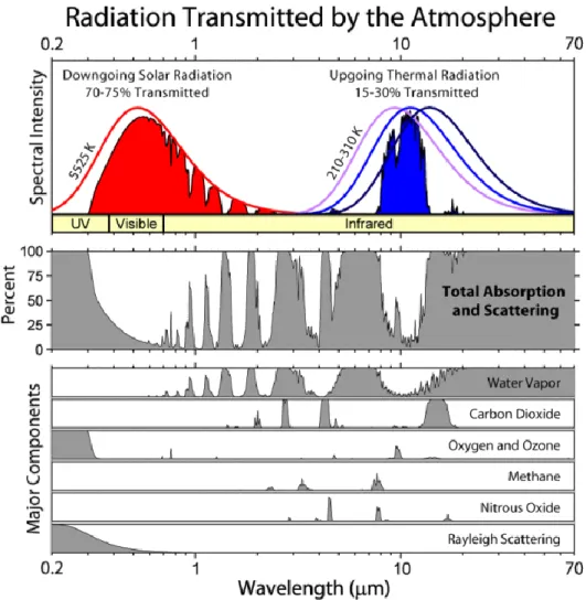
Carbon dioxide, methane, nitrous oxide and fluorinated gases are considered as greenhouse gases. The importance of these gases in the greenhouse effect depends on how long they remain in the atmosphere, their concentration or abundance, and the strength of their impact3. Methane and nitrous oxide absorb more heat per molecule than carbon dioxide, although carbon dioxide remains much more time in the atmosphere and is more abundant. It is considered that carbon dioxide is the responsible of two-thirds of the increase in the heat retention, and the carbon dioxide absorption spectra corresponds with the upgoing thermal radiation that is not transmitted4 (Figure 2). This means that
carbon dioxide emissions are the most important environmental problem that must be solved.
Introduction
11
Carbon dioxide is a colourless and odourless molecule that appears in a gas state at ambient conditions. Carbon dioxide is a non-polar molecule, and it remains in the atmosphere because it is chemically unreactive at standard conditions5.
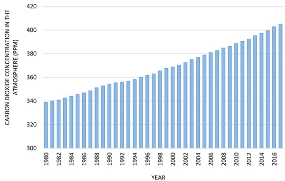
Carbon dioxide is generated by all aerobic organisms to produce energy by respiration, and it is a necessary compound for the growth of the plants. In this way, nature has acted as a regulator of carbon dioxide controlling its concentration in the atmosphere. However, the industrial revolution has led to an increase in the carbon dioxide emissions that nature cannot mitigate6. Nowadays, most of the emissions come from the combustion of fossil fuels to release energy that is commonly transformed into heat or electricity. On the other hand, carbon dioxide is used as a feedstock in some industrial processes, although this amount is low. As a result, carbon dioxide concentration has grown from 277 ppm before industrial revolution to more than 402 nowadays (Figure 3), and this increase is expected to exceed 500 ppm at the end of the century7.
Figure 3. Evolution of carbon dioxide concentration in the atmosphere (Dlugokencky et al., NOAA/ESRL (www.esrl.noaa.gov/gmd/ccgg/trends/). 300 320 340 360 380 400 420
1980 1982 1984 1986 1988 1990 1992 1994 1996 1998 2000 2002 2004 2006 2008 2010 2012 2014 2016
Introduction
12
The consequences of this increment in carbon dioxide emissions and the rise in global temperature are dramatic for the Earth. An important amount of this carbon dioxide has been absorbed by the oceans affecting their pH. With higher carbon dioxide concentrations and higher temperature oceans are more acid than normal, affecting the organisms that live in them8. Also animals and plants that live in the Earth’s surface are affected by this change that is expected to be the most important cause of species extinctions this century. Climate change is happenning so quickly that many species do not have enough time to adapt and they die9.
COP21 agreement in Paris was an important achievement in the fight against the climate change and is going to help in order to cut down on carbon dioxide emissions10. However, it is impossible to eliminate completely the carbon dioxide production from all the industrial and energy processes. For this reason, it is neccesary to find an alternative solution for the carbon dioxide produced.
Carbon dioxide utilization
Although fossil fuels are expected to continue being the main source of energy in the next years11, carbon dioxide emissions to the atmosphere could be reduced using new
Introduction
13
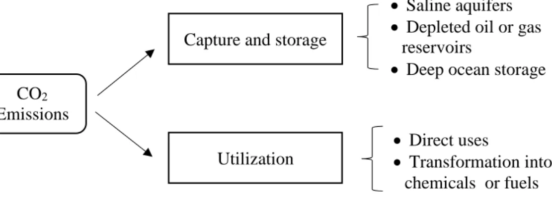
Figure 4. Possibilities to reduce carbon dioxide emissions to the atmosphere.
Many researchers have been focused on capture carbon dioxide efficiently and promising results have been obtained12,13. However, they are not still ready to manage huge amounts of carbon dioxide and the potential locations for its storage have not been decided nowadays because the safety of underground and ocean storage is still being studied. On the other hand, carbon dioxide can also be used in the industry in two different ways: direct use or its conversion to chemicals. Among the direct uses, carbon dioxide has been commonly used in many industries such as soft drink, food, foaming or fire-extinguishers. It has been used as solvent in many processes in order to help in cleaning or separation. Carbon dioxide has been injected into depleted oil (enhanced oil recovery) and natural gas field (enhanced coal-bed methane) to increase the reservoir internal pressure which ultimately lead to the increase of the productivity14.
In the last few years, supercritical carbon dioxide has also attracted much attention due to its properties that allow its use in different ways. Supercritical Antisolvent (SAS) technology has been used for the encapsulation of different active compounds related with food, agricultural or pharmaceutical industries with different benefits compared with conventional encapsulation technologies15. The use of supercritical carbon dioxide as a
CO2
Emissions
Capture and storage
Saline aquifers Depleted oil or gas
reservoirs
Deep ocean storage
Utilization
Direct uses
Introduction
14
medium for polymer synthesis and for polymer processing has shown some advantages. Particles from gas saturated solution (PGSS) technique is used to produce microparticles with different morphologies16. The production of new materials using supercritical carbon
dioxide has allowed the development of new products such as aerogels17, which show remarkable properties that make them suitable for hydrogen storage18 or catalytic processes19. However, the main use of supercritical carbon dioxide is found in the extraction of different compounds due to the use of lower temperatures that preserve the active compounds and the easier separation after the extraction. It has been used for the recovery of wine-must aroma compounds20, for the removal of 2, 4, 6 – tricholoroanisol from the cork stoppers of wine bottles21, or for the extraction of certain lipids22, among many examples.
Despite the multitude direct uses of carbon dioxide, the market of these processes is limited and its influence on the reduction of carbon dioxide is small. Because of it, carbon dioxide conversion to chemicals represents the best option due to the high potential market many products have, as it is shown in Table 1. These products represent a good opportunity due to their global demand23.
Table 1. Some potentialproducts from carbon dioxide as raw material. (Huang et al., Aerosol and Air Quality Research, 2014).
Product Reactants Potential of CO2
reduction (ton CO2/ton of
product)
Global production
Urea NH3 and CO2 0.75 198.4 MT/yr
Polycarbonate CO2, Propylene oxide 0.5 3.6 MT/yr
Methanol CO2 and H2 1.375 75 MT/yr
Dimethyl carbonate CH3OH and CO2 1.467 0.24 MT/yr
Introduction
15
Among carbon dioxide possible transformations into chemicals, conversion into fuels have attracted most of the attention in the last few years24. The use of fossil fuels, that are the main source of energy nowadays, is limited in time because the reserves decrease every year25. The synthesis of energetic products from carbon dioxide would help to find an alternative source of energy for the future. The synthesis of fuels from carbon dioxide can be performed following several routes.
Carbon dioxide transformation using microalgae has been studied in the last years26. Microalgae are a polyphyletic group of unicellular photosynthetic eukaryotes that grow fast due to their simple structure. Microalgae have high potential as biodiesel feedstock because their oil content may exceed 70 % (w/wDW), as compared with 5% of the best agricultural oil crops27. They provide higher effectiveness of energy conversion because
their metabolic functions demand less than other crops. The main problem is commonly to destroy the cell in order to extract the oil. Depending on the species of microalgae, they produce different kinds of hydrocarbons, lipids and other oils28. The optimization of their growth conditions can increase the oil concentration up to 80%.
Introduction
16
However, the most common transformation of carbon dioxide into fuels is the hydrogenation. Hydrogen is a high energetic material that can be used to reduce carbon dioxide31. The products obtained vary depending on the catalyst used and the pressure
and temperatures conditions32 (Figure 5).
Figure 5. Different products obtained from carbon dioxide hydrogenation. (Wang et al., Chemical Society Reviews, 2011).
From a thermodynamic point of view, these reactions usually have a positive change of enthalpy and they are endothermic. The use of homogeneous and heterogeneous catalysts is widely extended to perform these reactions. Homogenous catalytic systems usually show higher catalytic activity than heterogeneous catalysts33. On the other hand,
heterogeneous catalysts are better from the point of view of the reactor design, separation, handling, stability and reusability of the catalyst34. These advantages usually reduce the operation costs, which makes them the best option.
Among the different types of reactors, microreactors have shown many advantages that recommend their use in research scale. Their most important property is the high relation surface/volume provided35, which can be from 10000 to 50000 m2/m3. Conventional reactors used in laboratory provide around 1000 m2/m3, and industry reactors 100 m2/m3.
CO2 + H2
CO
HCOOH CH4
HCONR2 Hydrocarbons
CH3OCH3
CH3OH
Introduction
17
This increment entails a better heat transfer efficiency, creating a more stable temperature profile along the reactor. In microreactors mass transport limitations are minimized, with a reduction of mixing times as a consequence. Other advantages are the possibility to work in continuous, the lower amount of reactants used and the improvement in the safety36.
Methanol, formic acid or hydrocarbons are considered as potential fuels. We can find many studies concerning about the suitability of methanol for gasoline blends37, as well as concerning toxicology and environmental aspects of MeOH as a fuel. Methanol is a chemical commodity that is produced in the industry worlwide. It is produced performing a hydrogenation of carbon dioxide, where the catalysts used play an essential role in the selectivity of the reaction and the conversion achieved. Initially, the methanol synthesis from syngas was performed at 250 – 350 bar and 350 - 450 ºC. In the 70s the introduction of more active catalysts reduced these conditions down to 50 – 100 bar and 200 – 300 ºC.
The production of methanol from carbon dioxide can be performed in one single reaction. However, the conversion is increased when an intermediate step is included in order to produce first carbon monoxide which then reacts again with hydrogen to obtain methanol38.
𝐶𝑂2+ 𝐻2⇔ 𝐶𝑂 + 𝐻2𝑂; ∆𝐻0= +41.19 𝑘𝐽/𝑚𝑜𝑙 (1) 𝐶𝑂 + 2𝐻2⇔ 𝐶𝐻3𝑂𝐻; ∆𝐻0= −90.70 𝑘𝐽/𝑚𝑜𝑙 (2)
Many catalysts such as Cu, Ni, Ru, Pd, Mo or CeO2 have been studied in order to perform
Introduction
18
catalysts because the synergy created between both materials, achieved the highest selectivity to methanol40. Both are cheap and abundant materials, and their chemistry has been widely studied.
Current studies are focused on decreasing pressure and temperature conditions to carry out the reaction. The energy required for the reaction comes usually from burning fossil fuels, which limits the environmental application of this technology. Performing the carbon dioxide hydrogenation by means of renewable energies with good efficiencies is still a challenge and it is concentrating the research nowadays.
Surface Plasmon Resonance
Among renewable energies, many studies suggest that solar energy could be the most suitable choice to perform the reaction41. The use of solar energy to transform carbon dioxide is not new: plants show that this process can be carried out. In their case, carbon dioxide is transformed into glucose and oxygen using solar energy and water as a reactant (Figure 6).
Figure 6. Photosynthesis reaction to obtain glucose and oxygen from carbon dioxide.
Introduction
19
splitting of water using a TiO2 photoanode and a Pt cathode42. After this work, many
studies have been carried out in the development of photocatalytic CO2 conversion
systems43,44. The main problem of photocatalytic processes is the low efficiency due to
the insufficient use of all the energy from the sun. Most of the investigations have focused on semiconductor materials such as TiO2 due to their chemical stability45. However,
semiconductor materials absorb light in the ultraviolet band, which represents only about a 4% of the light spectrum. Because of it, many researchers work in different technologies with the aim of improving the efficiency of the photocatalytic processes.
The field of improvement consists on incorporating visible absorption of the light to this material. Some studies have been done working in the surface photosensitization46, although the most promising route is the combination with noble metals. It has been shown that noble metal nanoparticles such as gold or silver improve the photocatalytic activity of TiO2 in a higher scale than other materials47. This enhancement is due to a
phenomenon called surface plasmon resonance that increases the energy absorbed in the visible band by these nanoparticles.
Introduction
20
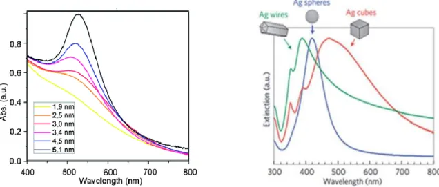
Figure 7. Light absorption of gold depending on the size of the nanoparticles (left) and light absorption of silver depending on the shape of the nanoparticles (right)(Nealon et al., Nanoscale, 2012; Valenti, et al.,
Journal of Materials Chemistry A, 2016).
Noble metal nanoparticles have free conduction band electrons that oscillate induced by the light radiation. When the oscillation frequency of light magnetic field is in accordance with that of free electrons, they start to oscillate. The surface plasmon polarization consists on magnetic waves that are propagated along the interface between materials with positive and negative permittivities, as it occurs in the intersection between a dielectric and a metal54. This effect only takes place when the size of the nanoparticles is much smaller than the wavelength of the light. Metals that have shown this effect are silver, gold, copper, aluminium, sodium and indium. The surface of the semiconductor or dielectric material must be free of other substances that can prevent the formation of the interface semiconductor – noble metal.
Introduction
21
with copper nanoparticles represents a possibility to reduce the temperature conditions required for the hydrogenation and a way to improve the efficiency of the light energy storage in methanol form.
References
1. Marland, G., Rotty, R.M., Greenhouse gases in the atmosphere: what do we know.
Journal of the Air Pollution Control Association, 1985, 35 (10), 1033 – 1038.
2. NOAA National Centers for Environmental information, Climate at a Glance: Global Time Series, published July 2018, from https://www.ncdc.noaa.gov/cag/.
3. Montzka, S.A., Dlugokencky, E.J., Butler, J.H., Non-CO2 greenhouse gases and
climate change. Nature, 2011, 476 (7358), 43 – 50.
4. Smit, B., et al., Introduction to carbon dioxide capture and sequestration (book). The
Berkeley Lectures on Energy, 2014, 1.
5. Joshi, P. B., Carbon dioxide utilization: A comprehensive review. International Journal of Chemical Sciences, 2014, 12 (4), 1208 1220.
6. Le Quéré, C., et al., Global Carbon Budget 2017, Earth System Science Data, 2018,
10(1), 405-448.
7. Dlugokencky, E., Tans, P., NOAA/ESRL (www.esrl.noaa.gov/gmd/ccgg/trends/). 8. Guinotte, J.M., Fabry, V.J., Ocean acidification and its potential effects on marine
ecosystems. Annals of the New York Academy of Sciences, 2008, 1134, 320 -342. 9. Garnier, J., Lewis, M.A., Expansion under climate change: The genetic consequences.
Bulletin of Mathematical Biology, 2016, 78(11), 2165 – 2185.
10.Christoff, P., The promissory note: COP 21 and the Paris Climate Agreement.
Environmental Politics, 2016, 25 (5), 765 – 787.
11.York, R., Do alternative energy sources displace fossil fuels? Nature Climate Change, 2012, 2 (6), 441 – 443.
Introduction
22
13.Leung, D.Y.C., Caramanna, G., Maroto-Valer, M.M., An overview of current status of carbon dioxide capture and storage technologies. Renewable and Sustainable
Energy Reviews, 2014, 39, 426 – 443.
14.Norhasyima, R.S., Mahlia, T.M.I., Advances is CO2 utilization technology: A patent
landscape review. Journal of CO2 Utilization, 2018, 26, 323 – 335.
15.Arango-Ruiz, A., et al., Encapsulation of curcumin using supercritical antisolvent (SAS) technology to improve its stability and solubility in water. Food Chemistry, 2018, 258, 156 – 163.
16.Labuschagne, P. W., Naicker, B., Kalombo, L., Micronization, characterization and in-vitro dissolution of shellac from PGSS supercritical CO2 technique. International
Journal of Pharmaceutics, 2016, 499, 205 – 216.
17.Fricke, J., Aerogels – highly tenuous solids with fascinating properties. Journal of
Non-Crystalline Solids, 1988, 100 (1-3), 169 – 173.
18.Rueda, M. et al., Improvement of the kinetics of hydrogen release from ammonia borane confined in silica aerogel. Microporous and Mesoporous Materials, 2017,
237, 189 – 200.
19.Wang, C.-T., Ro, S.-H., Nanocluster iron oxide-silica aerogel catalysts for methanol partial oxidation. Applied Catalysis A: General, 2005, 285 (1-2), 196 – 204.
20.Macedo, S., et al., Recovery of wine-must aroma compounds by supercritical CO2.
Food Bioprocess Technology, 2008, 1, 74 – 81.
21.Viguera, M. et al., The parameters that affect the supercritical extraction of 2,4,6-trichloroanisol from cork. Journal of Supercritical Fluids, 2018.
22.Sahena F., et al., Application of supercritical CO2 in lipid extraction – A review.
Journal of food engineering, 2009, 95, 240 – 253.
23.Huang, C.-H., Tan, C.-S., A review: CO2 Utilization. Aerosol and Air Quality
Research, 2014, 14 (2), 480 – 499.
24.Aresta, M., Dibenedetto, A., Angelini, A., The changing paradigm of CO2 utilization.
Introduction
23
25.Vernon, C., Thompson, E., Cornell, S., Carbon dioxide emission scenarios: limitations of the fossil fuel resource. Procedia Environmental Sciences, 2011, 6, 206 – 215.
26.Adeyeni, O.M., Azimov, U., Burluka, A., Algae biofuel: Current status and future applications. Renewable and Sustainable Energy Reviews, 2018, 90, 316 – 335. 27.Malcata, F.X., Microalgae and biofuels: A promising partnership?. Trends in
Biotechnology, 2011, 29 (11), 542 – 549.
28.Kleinová, A., et al., Biofuels from algae. Procedia Engineering, 2012, 42, 231 – 238. 29.Hegner, R., Rosa, L.F.M., Harnisch, F., Electrochemical CO2 reduction to formate at
indium electrodes with high efficiency and selectivity in pH neutral electrolytes.
Applied Catalysis B: Environmental, 2018, 238, 546 – 556.
30.Costentin, C., Robert, M., Savéant, J.-M., Catalysis of the electrochemical reduction of carbon dioxide. Chemical Society Reviews, 2013, 42(6), 2423 – 2436.
31.Federsel, C., Jackstell, R., Beller, M., State-of-the-art catalysts for hydrogenation of carbon dioxide. Angewandte Chemie – International Edition, 2010, 49 (36), 6254 – 6257.
32.Wang, W., et al., Recent advances in catalytic hydrogenation pf carbon dioxide.
Chemical Society Reviews, 2011, 40 (7), 3703 – 3727.
33.Wesselbaum, S., et al., Hydrogenation of carbon dioxide to methanol by using a homogeneous ruthenium-phosphine catalyst. Angewandte Chemie – International
Edition, 2012, 51 (30), 7499 – 7502.
34.Dang, S., et al., A review of research progress on heterogeneous catalysts for methanol synthesis from carbon dioxide hydrogenation. Catalysis Today, 2018. 35.Salmi, T. O., Mikkola, J.-P., Warna, J. P., Chemical reaction engineering and reactor
technology (book). Chemical Industries, 2011, 125.
Introduction
24
37.Yanju, W., et al., Effects of methanol/gasoline blends on a spark ignition engine performance and emissions. Energy and Fuels, 2008, 22 (2), 1254 – 1259.
38.Joo, O.-S., et al., Carbon dioxide hydrogenation to form methanol via a reverse-water-gas-shift traction (the CAMERE process). Industrial and Engineering Chemistry
Research, 1999, 38 (5), 1808 – 1812.
39.Natesakhawat, S. et al., Active sites and structure-activity relationships of copper-based catalysts for carbon dioxide hydrogenation to methanol. ACS Catalysis, 2012,
2 (8), 1667 – 1676.
40.Burch, R., Chappell, R.J., Golunski, S.E., Synergy between copper and zinc oxide during methanol synthesis. Transfer of activating species. Journal of the Chemistry
Society, Faraday Transactions 1: Physical Chemistry in Condensed Phases, 1989, 85
(10), 3569 -3578.
41.Aresta, M., Dibenedetto, A., Angelini, A., The use of solar energy can enhance the conversion of carbon dioxide into energy-rich products: Stepping towards artificial photosynthesis. Philosophical Transactions of the Royal Society A: Mathematical,
Physical and Engineering Sciences, 2013, 371 (1996), 0111.
42.Fujishima, A., Honda, K., Electrochemical photolysis of water at a semiconductor electrode. Nature, 1972, 238, 37 – 38.
43.Yaron, P. Application of TiO2 photocatalysis for air treatment: patent’s overview.
Applied Catalysis B: Environmental, 2010, 99, 448 – 460.
44.Li, X., et al., Photocatalytic reduction of CO2 over noble metal-loaded and
nitrogen-doped mesoporous TiO2. Applied Catalysis A, 2012, 429-430, 31 – 38.
45.Schneider, J., et al., Understanding TiO2 photocatalysis: Mechanisms and materials
(Review). Chemical Reviews, 2014, 114 (19), 9919 – 9986.
46.Islam, A., Sugihara, H., Arakawa, H., Molecular design of ruthenium (II) polypyridyl photosensitizers for efficient nanocrystalline TiO2solar cells. Journal of
Introduction
25
47.Liu, E. et al., Photocatalytic reduction of CO2 into methanol over Ag/TiO2
nanocomposites enhanced by surface plasmon resonance. Plasmonics, 2014, 9, 61 – 70.
48.Maier, S.A., Plasmonics: Fundamentals and applications (Book), 2007, 1 – 223. 49.Willets, K.A., Van Duyne, R.P., Localized Surface plasmon resonance: spectroscopy
and sensing. Annual Review of Physical Chemistry, 2007, 58, 267 – 297.
50.Wei, W., et al., Graphene/Au – enhanced plastic clad silica fiber optic surface plasmon resonance sensor. Plasmonics, 2018, 13 (2), 483 – 491.
51.Wu, T., et al., Surface plasmon resonance-induced visible light photocatalytic reduction of graphene oxide: Using Ag nanoparticles as a plasmonic photocatalyst.
Nanoscale, 2011, 3 (5), 2142 – 2144.
52.Nealon, G.L., et al., Magnetism in gold nanoparticles. Nanoscale, 2012, 4 (17), 5244 -5258.
53.Valenti, M., et al., Plasmonic nanoparticle-semiconductor composites for efficient solar water splitting. Journal of Materials Chemistry A, 2016, 4 (46), 17891 – 17912. 54.Saryche, A.K., Shets, G., Shalaev, V.M., Magnetic plasmon resonance. Physical
Objectives
29
Many processes have been proposed in order to transform carbon dioxide into different products and help to mitigate climate change by decreasing carbon dioxide emissions. Among them, transformation into fuels offers an added value to the process, opening the possibility to make the transformation economically viable. Carbon dioxide hydrogenation produces methanol which is considered as a fuel with a high global demand.
In this work, light energy is proposed to be the only source of energy used to perform the reaction avoiding the use of fossil fuels to obtain the energy required for the reaction and the subsequent carbon dioxide production. Different catalysts have been studied in the field of photocatalysis, although the efficiencies of the processes are still low. Some technologies have tried to improve the light absorption of the catalysts, and surface plasmon resonance has been shown to be a useful alternative to increase the energy absorbed in the visible band.
The general aim of this work is to perform the hydrogenation of carbon dioxide by means of light energy. In order to achieve this general goal, several specific objectives must be developed:
Synthesis of catalysts and supports that enhance the conversion of CO2 by means
of light energy. This objective involves the development of a catalytic system composed by noble metal nanoparticles able to show the surface plasmon resonance effect, and a transparent support with high surface area that allows light to reach the nanoparticles inside and activate the catalyst.
Objectives
30
pressure), and a method to analyze the gas outlet in line. Special emphasize will be given to the reactor, developing a procedure to impregnate glass microreactors homogeneously with the synthesized catalysts, as well as to conceive a light-emitting diode assembly able to illuminate the entire reactor, providing light in the most homogeneous way possible.
CHAPTER 1
A device for CO
2
reduction using plasmonic
Chapter 1 A device for CO2 reduction using plasmonic catalyst activation
33
1. Introduction
1.1. CO2 as a renewable energy vector
One of the most industrially promising heterogeneous catalytic processes is carbon dioxide hydrogenation. In the process of catalytic hydrogenation, hydrogen obtained from carbon neutral energy sources (e.g. wind or solar) is reacted with CO2 to obtain products
such as fuels1. Thus, this process will then serve a double purpose: first, as a chemical
storage of the surplus energy generated by the fluctuating renewable energies; and second, to reduce the emissions of CO2.
Successful introduction of the CO2-use technologies require of plausible and profitable
processes that use efficiently renewable energy. The most abundant and evenly distributed of such energies is the one provided by sun. If stored in the form of “solar commodities” such as methanol or olefins new opportunities for use of CO2 could be
opened2. The production of methanol from CO
2 and hydrogen involves the following
reactions:
𝐶𝑂2+ 𝐻2⇔ 𝐶𝑂 + 𝐻2𝑂; ∆𝐻0= +41.19 𝑘𝐽/𝑚𝑜𝑙 (1)
𝐶𝑂 + 2𝐻2⇔ 𝐶𝐻3𝑂𝐻; ∆𝐻0= −90.70 𝑘𝐽/𝑚𝑜𝑙 (2)
𝐶𝑂2+ 3𝐻2⇔ 𝐶𝐻3𝑂𝐻 + 𝐻2𝑂; ∆𝐻0= −49.51 𝑘𝐽/𝑚𝑜𝑙 (3)
A device for CO2 reduction using plasmonic catalyst activation Chapter 1
34
electricity and then, the resultant electrical energy is used in the chemical transformations of CO23-7; the thermal routes concentrate the solar radiation and convey that energy
directly into the reactor8-10. Photocatalytic CO
2 conversion involves either the water
splitting connected to a CO2 reduction reaction, or a process combining both in one
“single pot”11-13.
1.2. Selective use of visual light with plasmon catalysts
Surface Plasmon Resonance (SPR) phenomenon is commonly found in metallic (or carbon) nanostructures and allows to increase the range of the solar spectrum used on a given photoinduced process14. This effect is the result of the response of the conduction electrons to the oscillations of the electric field of the light radiation. An increased energy absorption by the electrons is possible at selected wavelengths under the proper particle size and shape of the nanoparticles for a given surrounding media (fluid or catalyst). This phenomenon produces high light concentration up to the point that a reduction in the amount of semiconductor of three orders of magnitude for the same amount of light has been possible15. On the other hand, increased light capture with SPR for photothermal conversions are leading to breakthroughs in energy systems such solar collectors16. This work explores the reduction of CO2 to CO as a first step in a solar-based process to
produce methanol. Thus, it is based on the Reverse Water Gas Shift (RWGS) reaction as described by the equation (1). Recent approaches have used gold and semiconductor composites for plasmonic enhancement of the reduction17, 18.
Yet, this process is commonly activated in industry using Cu/ZnO based catalysts19.
Chapter 1 A device for CO2 reduction using plasmonic catalyst activation
35
been developed. For this, the plasmon-tuneable Cu/ZnO catalyst reported by Tan et al. (2013)20 has been used.
1.3. A plasmonic microreactor as a light harvesting device
The efficiency of the chemical reactions is not ruled only by the catalytic material but also for the reactor configuration and their mass and energy transport characteristics. Many times promising catalytic materials fail to reach industrial success owing to the disconnection between the catalytic structure and the reactor-level phenomena21, 22. In this work, it is proposed a novel concept for visual energy harvesting: a plasmonic microreactor device. It integrates plasmon catalyst, and reactor as one entity with a sole response to light (Figure 1.1).
Figure 1.1. Concept of the plasmonic microreactor device.
A device for CO2 reduction using plasmonic catalyst activation Chapter 1
36
plasmonic absorption of solar energy by the catalyst would represent a major breakthrough in the CO2-use field.
During this work, a plasmon-tuneable composite is integrated with a microchannel based reaction system under visual LED illumination for the RWGS reaction. This has involved the synthesis of the new composite; the development of an impregnation method to create a catalyst-reactor entity; finally, the assembly of a reaction system to test the reaction.
2. Methods
2.1. Plasmo-catalytic composites synthesis
The chemicals used during this stage are detailed: Zinc acetate dihydrate (>98%), oleylamine (70%), tetramethyl orthosilicate (98%), ammonia (28-30%), triethylenglicol (99%) were purchased from Sigma-Aldrich. Ethylenglicol (99.5%) (Merck). Copper acetate monohydrate (99.9%) was purchased from Alfa Aesar. Methanol (99.8%) (Panreac). All chemicals were used without further purification.
2.2. Synthesis of Cu/ZnO bimetallic catalyst
This bimetallic (Cu:ZnO, 1:2) catalyst was synthesised following the procedure proposed by Tan et al (2013)20.
Chapter 1 A device for CO2 reduction using plasmonic catalyst activation
37
centrifuged in order to isolate the precipitate. It was washed with 6 ml of ethanol three times to ensure complete removal of the reactants or byproducts.
ZnO nanorods prepared above were then redispersed in 20 ml of triethylenglicol by sonication for two hours, followed by stirring under room conditions overnight. Ethylenglicol (2ml) was added to the ZnO dispersion, and the mixture was degassed at room temperature for 5 min before heating to 190 ºC. Simultaneously, a second solution of copper acetate monohydrate was prepared dissolving in ethylenglicol. This mixture required sonication in order to dissolve well the copper acetate in the liquid. This mixture was added to the ZnO mixture in a dropwise manner during 10 min. After this, 5 min more at 190 ºC were allowed before the composite was washed with isopropanol, centrifuged during 15 minutes at 4500rpm (centrifuge Kubota 5100, Japan) and isolated from the mixture.
2.3. Synthesis of mesoporous silica composites
Light transmission to the catalytic structures is essential while enough surface area has to be provided in order to have enough metal loads to capture light. Transparent aerogels are mesoporous materials combining high surface areas and good light transmission23. Aerogels were synthesised following the sol-gel route. The precursor for the silica hydrogel selected was the tetramethyl orthosilicate (TMOS). The molar ratio TMOS: CH3OH: H2O: NH4, was 1 : 2.3 : 3.84 : 0.012 .
A device for CO2 reduction using plasmonic catalyst activation Chapter 1
38
and stirred. After a few minutes of stirring, both solutions were mixed, and the gelation process began. In this moment, the gelation process of the silica hydrogel has started, but it is still liquid for a few minutes. This time lapse, before gelation, must be used to impregnate the solution inside the microchannels of the microreactors.
2.4. Integration of composites and microreactor
In order to have a single integrated device it is necessary to integrate light transmission and composite activation in the same structure. Here, we have developed a method to integrate transparent aerogels in glass microchannels. The method used to make the impregnation of the sol-gel that showed best results was the suction of the liquid with a syringe, which was previously adapted to the microreactor on its top (Figure 1.2). With this method, placing the microreactor in vertical position, it was very easy to fill the microchannel placing the tip in the liquid. After a short time, the gelation process finished and the hydrogel formed had a good adherence inside the microchannels.
Figure 1.2. Syringe filling microchannels.
Chapter 1 A device for CO2 reduction using plasmonic catalyst activation
39
use an amount of ammonia low enough that allows to have enough time to impregnate the hydrogel inside the microreactor, because it must be still a fluid. On the other hand, the amount of ammonia cannot be very low, because if the gelation process is too slow, the nanoparticles start to precipitate and they will not be inside the silica net. Finding an equilibrium between this two factors is the key to achieve a good impregnation of the nanoparticles supported in the silica gels inside the microreactors.
In order to ensure a good adherence of the aerogel to the walls of the microchannels, it is necessary to perform a pre-treatment to the glass microreactors (15.0 cm) to clean the walls of the microchannels. For this cleaning process, the most common option is to use a piranha solution, which reacts violently with most organic materials. The solution used was a mixture of sulfuric acid and hydrogen peroxide that can be prepared in different proportions, the most usual 4:1 in concentrated sulfuric acid. From 15 to 30 minutes the material is submerged in the solution, then removed, washed with plenty Milli-Q water and dried carefully.
The empty glass microreactors were put inside a glass pot, and the sulfuric acid was first added. Then, the hydrogen peroxide was also added with extreme care because the reaction is very exothermic, the temperature is suddenly increased and some vapours can be formed. After 20 minutes, the slides were removed from the piranha solution, washed with Milli-Q water and dried carefully.
A device for CO2 reduction using plasmonic catalyst activation Chapter 1
40
resulting into alcogels. After 24 hours of heating, the alcogels were dried using supercritical carbon dioxide. The microreactors were put in a high pressure vessel, and this vessel was filled completely with methanol. Carbon dioxide was introduced slowly in the vessel to allow a good diffusion into the methanol. The pressure was raised to 100 bar and the temperature to 40 ºC, above thecritical point of carbon dioxide. Three cycles of 45 minutes were performed, renewing the carbon dioxide between each cycle to complete the drying process24. After this, silica aerogels were correctly obtained, keeping the adherence to the walls of the microchannels.
2.5. Proof-of-concept setup
Once Cu/ZnO based plasmonic composites were integrated into the glass microchannels, a test of these devices was made. In order to test the reactor concept, a reaction system has been built that included visual LED illumination and control of temperature the reaction while a precise control of flow and pressure is provided. A scheme of the experimental plant is presented in Figure 1.3.
Chapter 1 A device for CO2 reduction using plasmonic catalyst activation
41
Hydrogen and carbon dioxide were introduced in the system, and their flows were controlled with two different flow mass meter/controllers (EL-Flow F-200, Bronkhorst) with ranges from 0.02 to 1 ml/min.
Before the reaction was initiated, hydrogen and carbon dioxide were mixed in a 3:1 proportion, and sent to the vent while both flows were stabilized.
When the flows were correctly controlled, the mixture of the gases went to the second part of the setup. In this part the gases were heated, together with the glass microreactor, in a gas chromatography oven (Agilent 7890). The microreactor consisted on a 0.5 mm ID glass capillary with an external diameter of 5 mm (Schott Duran, USA).
A second vent was used to take out the gases while the pressure was increasing to 20 bar. Pressure was controlled by a pressure meter/controller (EL-Press series, Bronkhorst). When pressure and flows were stable at 20 bar, the valve for extraction was closed, and the oven and LEDs were turned on.
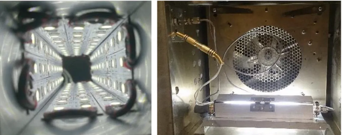
Visual light stimulation was provided by 36 LEDs (Superbright, inspired LED) surrounding the microreactor, as shown in Figure 1.4. In total, they provided the equivalent to a nominal power of 9780 W/m2 of white light.
A device for CO2 reduction using plasmonic catalyst activation Chapter 1
42
The reaction began and the products of the reaction were measured in a Micro Gas Chromatograph (CP-4900, Varian) equipped with two columns: a poraplot 10m and a 5A molsieve. Before the micro GC, the pressure of the gas stream was reduced to less than 5 bar.
2.6. Composites characterization
Scans of the bimetallic catalysts to check absorbance of visual light were carried out in a UV-Vis spectrometer (UV 2550, Shimadzu). XRD analysis were carried out in a Bruker Discover D8 diffractometer. The porosity measurements were carried out in a Surface Area and Porosity Analyser (ASAP 2020, Micromeritics).
3. Results and discussion
3.1. Composites Characterization
After the synthesis UV-Vis scans were made in order to check the absorption of visual light from both the ZnO nanorods and the bimetallic Cu/ZnO catalyst (Figure 1.5).
Chapter 1 A device for CO2 reduction using plasmonic catalyst activation
43
It can be seen that the bimetallic catalyst have a peak at 498 nm. This correspond to the absorption of the range close to the green colour25. The transparent aerogels change and acquire colour once the composite is formed (Figure 6). It can be seen that the bimetallic catalyst have a peak at 498 nm. This correspond to the absorption of the range close to the green colour25. The transparent aerogels changed and acquired colour once the composite was formed (Figure 1.6).
Figure 1.6. Silica aerogel before (left) and after (right) catalyst impregnation.
A device for CO2 reduction using plasmonic catalyst activation Chapter 1
44
Figure 1.7. XRD pattern of the plasmonic composite.
BET surface area and pore volume of the samples were calculated from N2 isotherm. The
adsorption-desorption curve show a type IV isotherm curve typical for mesoporous silica aerogels26 (Figure 1.8). The BET surface area is 945.8 m2/g which indicates that the inclusion of the bimetallic catalyst does not have a significant influence on the textural properties of the aerogel. The BJH pore volume is equal to 2.29 cm3/g reinforcing that the structure is not affected.
Chapter 1 A device for CO2 reduction using plasmonic catalyst activation
45
3.2. Reaction test of the concept
The full power of the LED was applied and the evolution of the compounds were followed. In order to test the influence of the main variables of the process, changes in flow and temperature were made during the reaction (Figure 1.9).
It could be observed that the reaction was stable at 50 °C during more than 100 minutes. Then the temperature was increased at 70 °C and tested during the same time span. Finally, the flow was reduced to half of the initial condition. No significant changes were observed during almost 300 minutes. Which indicates the suitability of this system to test several catalyst loads and thermodynamic conditions.
Figure 1.9. Evolution of the reaction.
A device for CO2 reduction using plasmonic catalyst activation Chapter 1
46
chemistry as a mean to introduce renewable energy in the economy. Particularly, for the conversion of CO2.
4. Conclusions
A novel plasmonic composite was developed that can absorb light from the visible spectrum. Its characterization evidenced a high surface area and a proper integration with the metallic components of the catalyst.
It was then possible to introduce this composite into glass microchannels in order to obtain a single entity that acts as both a light-harvesting device and as a reactor. This is possible owing to the development of a simple yet effective impregnation method that allows the synthesis of the aerogels “in situ”.
The microreactor obtained was tested for RWGS in a system that allowed not only to control the reaction variables such pressure, temperature and flow. But also, delivers visual light in an elegant way.
The CO2 conversion rates were in accordance to other works testing plasmonic catalysts
Chapter 1 A device for CO2 reduction using plasmonic catalyst activation
47
References
1. Centi, G., Quadrelli, E. A., Perathoner, S., Catalysis for CO2 conversion: A key
technology for rapid introduction of renewable energy in the value chain of chemical industries. Energy & Environmental Science, 2013, 6, 1711-1731.
2. Centi, G., Perathoner, S., Green Carbon Dioxide: Advances in CO2 Utilization(book),
eds. G. Centi and S. Perathoner, 2014, vol. John Wiley & Sons.
3. Ogura, K., Yano, H., Tanaka, T., Selective formation of ethylene from CO2 by catalytic
electrolysis at a three-phase interface. Catalysis Today, 2004, 98, 515-521.
4. Angamuthu R., et al., Electrocatalytic CO2 conversion to oxalate by a copper complex.
Science, 2010, 327, 313-315.
5. Li, H., et al., Integrated electromicrobial conversion of CO2 to higher alcohols. Science,
2012, 335, 1596.
6. Rosen, B. A., et al., Ionic liquid-mediated selective conversion of CO2 to CO at low
overpotentials. Science, 2011, 334, 643-644.
7. Barton, E. E., Rampulla, D. M., Bocarsly, A. B., Selective solar-driven reduction of CO2 to methanol using a catalyzed p-GaP based photoelectrochemical cell. Journal of the
American Chemical Society, 2008, 130, 6342-6344.
8. Smestad, G. P., Steinfeld, A., Review: Photochemical and thermochemical production of solar fuels from H2O and CO2 using metal oxide catalysts. Industrial & Engineering
Chemistry Research, 2012, 51, 11828-11840.
9. Ermanoski, I., Miller, J.E., Allendorf, M.D., Efficiency maximization in solar-Thermochemical fuel production: Challenging the concept of isothermal water splitting.
Physical Chemistry Chemical Physics, 2014, 16, 8418-8427.
10. Forster, M., Investigations to convert CO2, NaCl and H2O into Na2CO3 and HCl by
thermal solar energy with high solar efficiency. Journal of CO2 Utilization, 2014, 7, 11-18.
11. Dhakshinamoorthy, A., et al., Photocatalytic CO2 reduction by TiO2 and related
A device for CO2 reduction using plasmonic catalyst activation Chapter 1
48
12. Tran, P. D., et al., Recent advances in hybrid photocatalysts for solar fuel production.
Energy & Environmental Science, 2012, 5, 5902-5918.
13. Neațu, Ș., Maciá-Agulló, J., Garcia, H., Solar light photocatalytic CO2 reduction:
General considerations and selected bench-mark photocatalysts. International Journal of
Molecular Sciences, 2014, 15, 5246.
14. Linic, S., Christopher, P., and Ingram, D.B., Plasmonic-metal nanostructures for efficient conversion of solar to chemical energy. Nature Materials, 2011, 10, 911-921. 15. Hägglund, C., Apell, S. P., Kasemo, B., Maximized optical absorption in ultrathin films and its application to plasmon-based two-dimensional photovoltaics. Nano Letters, 2010, 10, 3135-3141.
16. Garcia, M. A., Surface plasmons in metallic nanoparticles: Fundamentals and applications. Journal of Physics D: Applied Physics, 2011, 44, 283001.
17. Upadhye, A. A., et al., Plasmon-enhanced reverse water gas shift reaction over oxide supported Au catalysts. Catalysis Science & Technology, 2015, 5, 2590-2601.
18. Wang, C., et al., Visible light plasmonic heating of Au–ZnO for the catalytic reduction of CO2. Nanoscale, 2013, 5, 6968-6974.
19. Behrens, M., et al., The active site of methanol synthesis over Cu/ZnO/Al2O3
industrial catalysts. Science, 2012, 336, 893-897.
20. Tan, Z. Y., et al., Nanostructured Cu/ZnO coupled composites: Toward tunable Cu nanoparticle sizes and plasmon absorption. The Journal of Physical Chemistry C, 2013,
117, 10780-10787.
21. Gascon, J., et al., Structuring catalyst and reactor - An inviting avenue to process intensification. Catalysis Science & Technology, 2015, 5, 807-817.
22. Louis, B., et al., Rational Design of Microporous and Mesoporous Solids for Catalysis: From the Molecule to the Reactor. ChemCatChem, 2011, 3, 1263-1272. 23. Pajonk, G. M., Transparent silica aerogels. Journal of Non-Crystalline Solids, 1998,
Chapter 1 A device for CO2 reduction using plasmonic catalyst activation
49
24. Sanz-Moral, L. M., et al., View cell investigation of silica aerogels during supercritical drying: Analysis of size variation and mass transfer mechanisms. The
Journal of Supercritical Fluids, 2014, 92, 24-30.
25. NASA, What Wavelength Goes With a Color?,
http://science-edu.larc.nasa.gov/EDDOCS/Wavelengths_for_Colors.html.
26. Al-Oweini, R., El-Rassy, H., Surface characterization by nitrogen adsorption of silica aerogels synthesized from various Si(OR)4 and R″Si(OR′)3 precursors. Applied Surface
CHAPTER 2
Chapter 2 Study of the influence of the reaction variables
53
1. Introduction
Carbon dioxide conversion into useful products is attracting much attention in the last years as a way to reduce greenhouse effect and its dramatic consequences for the planet1,2. Among the options to perform this CO2 conversion, photocatalytic processes using solar
energy are presented as an interesting way to transform CO2 due to the use of a renewable
energy. CO2 can be transformed into methanol which is a chemical commodity and can
store the energy from the sun3,4. Transforming CO2 into methanol using solar energy
generates therefore two benefits at the same time: the reduction of CO2 emissions and the
storage of energy from renewable sources.
Photocatalytic CO2 transformation usually shows low conversions because the efficiency
of the process is limited5. One of the reasons is that most of the catalysts just absorb a little amount of the light energy in the visible or ultraviolet band. Surface Plasmon Resonance (SPR) is a phenomenon found in some metallic nanostructures that results in a higher light energy absorbance that can be controlled with the shape and size of the nanoparticles. Commonly, gold and silver nanoparticles have been studied to enhance SPR effect6,7, although other metals such as copper also produce this effect8. Similarly,
copper has been widely used for carbon dioxide hydrogenation in industry combined with the use of zinc oxide in order to produce methanol with high selectivity9. For this reason, a combination of both materials Cu/ZnO could be also used to perform carbon dioxide hydrogenation by means of solar energy using SPR as a way to enhance the efficiency of the process and to maximize the CO2 transformation.
Study of the influence of the reaction variables Chapter 2
54
importance to maximize this contact area with the synthesis method chosen. For this reason, it is needed to synthesize discrete copper nanoparticles whose final size can be controlled and to deposit them onto zinc oxide nanoparticles avoiding agglomeration.
Carbon dioxide and hydrogen can produce methanol directly in a one-step reaction. However, the conversion is increased when the transformation is carried out in two steps12. First, carbon dioxide is transformed in carbon monoxide (endothermic) and after this CO again with hydrogen produce methanol (exothermic).
In this work, glass microreactors are selected to perform the carbon dioxide hydrogenation because they provide great homogeneity in the light distribution through the reactor13. Glass microreactors avoid light absorption interferences, allowing to study the influence of the material properties and reaction conditions in CO2 conversion.
In order to fix the catalyst inside the microreactors a support is required. This support must provide high surface areas to load the bimetallic catalyst, ensuring that light is not absorbed by the support and can reach the catalyst to activate it. Silica aerogels are micro-mesoporous materials with high surface areas (400 -1500 m2/g) and high visible transparency14, properties that place them as the best option to be used as a support in this work.
Chapter 2 Study of the influence of the reaction variables
55
variables such as temperature, pressure, catalyst amount and reactants proportion is going to be performed.
2. Experimental methods
2.1. Reagents
The chemicals used during this stage were: Zinc acetate dihydrate (>98%), oleylamine (70%), tetramethyl orthosilicate (98%), ammonia (30%), triethylenglicol (99%) were purchased from Sigma-Aldrich. Ethylenglicol (99.5%) (Merck). Copper acetate monohydrate (99.9%) was purchased from Alfa Aesar. Methanol (99.8%) was purchased from Panreac.
2.2. Synthesis of plasmonic catalyst
Following the method proposed by Tan et al (2013)16, zinc oxide nanorods can be developed firstly and then copper nanoparticles are deposited onto in a second step controlling the final size of the nanoparticles and the wavelength where visual light is absorbed.
Study of the influence of the reaction variables Chapter 2
56
with 5 ml of ethanol to ensure a perfect removal of the reactants. ZnO nanorods prepared were redispersed in 20 ml of triethylenglicol for two hours by sonication, and then stirred under room conditions overnight.
After that, a dual glycol system was prepared to deposit copper oxide nanoparticles onto the ZnO nanorods. 1.5 mmol of copper acetate was added in a second pot to 4 ml of ethylenglicol, using sonication for 1h to create a homogeneous solution. 2 ml of ethylenglicol were also added to the zinc oxide vessel, and the solution was transferred to a three necked flask again to be degassed at ambient temperature for 10 min. Then, the copper acetate solution was placed in an addition funnel connected to the three necks flask with the copper oxide, which was heated at 190 ºC under nitrogen purging. To avoid agglomeration, copper acetate solution was added slowly drop by drop during 10 min. After this, the solution was cooled for being then washed and centrifuged three times with isopropanol at 5000 rpm.
2.3. Synthesis and impregnation of silica aerogels
The silica gels were synthetized following the method used by Sanz-Moral et al. (2014)17. The precursors used were tetramethyl orthosilicate (TMOS), methanol, water and ammonia in a 1 : 2.3 : 3.84 : 0.012 molar ratio. The amount of ammonia has been shown as the controlling parameter for the gelation time. Depending on the catalyst load, which also affects the gelation time, molar ratio TMOS: ammonia was varied from 1 : 0.012 to 1 : 0.12 in order to achieve the right gelation time.
Chapter 2 Study of the influence of the reaction variables
57
that was used before to suspend the catalyst nanoparticles by sonication. After that, methanol was mixed with the other precursors generating the silica net with Cu/ZnO catalyst inside. This silica structure was in a liquid form for a few seconds, which allowed the impregnation in glass microreactors by using just a syringe. Then, the gelation process took place directly inside the microreactors obtaining a hydrogel well attached to the walls of the microchannels and avoiding problems of introducing a solid catalyst in a narrow microchannel. Gelation time turns into the key factor for the catalyst impregnation inside the microreactors. Gelation must be slow enough to allow injection with the syringe, although if it is too slow precipitation of the catalyst will start and the final structure will not be homogeneous.
First, methanol with the catalyst nanoparticles was mixed with TMOS in a small glass and stirred for a few minutes. At the same time, a second glass with water and ammonia was also stirred and covered to avoid ammonia evaporation. Then, both solutions were mixed and the syringe was used to fill the microreactor. After a few seconds, the liquid turned into the hydrogel with the catalyst inside showing good adhesion and homogeneity along the entire length of the glass microreactor (15 cm).
2.4. Aerogels supercritical drying
Before carrying out the drying with supercritical CO2, an intermediate step was required
for aging the hydrogels18. In this stage, the microreactors were placed in a vessel filled with methanol and closed for one week. The aim was to exchange the water in the aerogel for methanol producing alcogels that were dried later with supercritical CO2. In order to