TUTORIAL OSCILOSCOPIO TDS 1012 Parte 2
Material tomado de:
1. Tektronix. TDS1000B and TDS2000B Series Oscilloscopes Operator Training Kit Manual. 071-2199-01. Copyright © Tektronix.
2. Tektronix. Probe Fundamentals. 60W-6053-10_edu . Copyright © 2009, Tektronix 3. Tektronix. Fundamentals of Floating Measurements and Isolated Input
Oscilloscopes. Application Note. 3AW-19134-2. Copyright © 2011, Tektronix. 4. Tektronix. XYZs of Oscilloscopes. Primer. EA/FCA-POD 03W-8605-6. TEK1511
Copyright © 2011
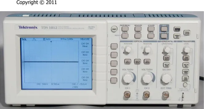
Figure 1 Front Panel
Primary Controls
The TDS1000B and TDS2000B Series Oscilloscopes provide different controls to modify different components of the displayed waveform. This section describes the following primary controls on the front panel:
• VERTICAL Controls • HORIZONTAL Controls • TRIGGER Controls
• MENUS Function Controls
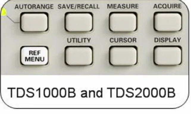
You use the Menu Function Controls at the top of the front panel to perform various functions, such as saving and recalling setups and waveforms, taking automatic waveform measurements, and modifying the acquisition settings. This section contains labeled pictures to describe the following
Menu Buttons:
• ACQUIRE button • DISPLAY button • CURSOR button • MEASURE button • SAVE/RECALL button • UTILITY button • REF MENU button • AUTORANGE button
The Menu Function Controls consist of eight menu-based function buttons. When you push a menu function button, the associated menu option options on the oscilloscope screen are activated. Figure 2 shows the front panel menu function controls.
Figure 2. Menu function controls
ACQUIRE Menu Function Controls
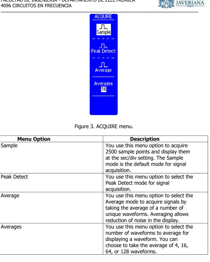
You use the ACQUIRE Menu Function Controls to regulate the signal acquisition and processing system and select different types of acquisition modes for a signal.
Figure 3. ACQUIRE menu.
Menu Option Description
Sample You use this menu option to acquire
2500 sample points and display them at the sec/div setting. The Sample mode is the default mode for signal acquisition.
Peak Detect You use this menu option to select the
Peak Detect mode for signal acquisition.
Average You use this menu option to select the
Average mode to acquire signals by taking the average of a number of unique waveforms. Averaging allows reduction of noise in the display.
Averages You use this menu option to select the
number of waveforms to average for displaying a waveform. You can choose to take the average of 4, 16, 64, or 128 waveforms.
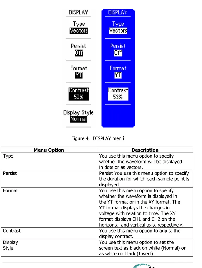
DISPLAY Menu Function Controls
You can control each menu option by pushing the side-screen menu button next to the option.
Figure 4. DISPLAY menú
Menu Option Description
Type You use this menu option to specify
whether the waveform will be displayed in dots or as vectors.
Persist Persist You use this menu option to specify
the duration for which each sample point is displayed
Format You use this menu option to specify
whether the waveform is displayed in the YT format or in the XY format. The YT format displays the changes in voltage with relation to time. The XY format displays CH1 and CH2 on the horizontal and vertical axis, respectively.
Contrast You use this menu option to adjust the
display contrast. Display
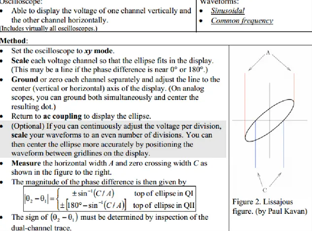
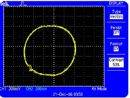
Example # 1 Using the XY Display Mode
You can display waveforms in the XY or YT formats. When you choose the XY display format, Channel 1 is displayed on the horizontal axis and Channel 2 is displayed on the vertical axis. When you choose the YT format, the vertical voltage is displayed in relation to time.
You use the XY display format to measure the phase relationship between two or more synchronous signals
Figure 5 displays two signals in the XY format with 90° phase shift.
Figure 5: XY Display of two sine waves with 90º phase shift
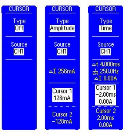
CURSOR Menu Function Controls
You use the CURSOR Menu Function Controls to make parametric amplitude and time measurements on a selected waveform.
To activate the CURSOR menu, push the CURSOR menu button. Figure 7 shows the menu-based options for the CURSOR menu function controls. You control each menu option by pushing the side-screen button next to the option.
Figure 7. CURSOR menu
Menu Option Description
Type You use this menu option to specify
cursor measurements of Amplitude or Time.
Source You use this menu option to choose
Delta You use this menu display to observe the numerical difference between the quantities represented by the cursors.
Cursor 1 You use this menu display to adjust the
position of cursor 1 and to observe the quantity represented by cursor 1. This could either be the time referenced to the trigger position, or the voltage referenced to the ground.
Cursor 2 You use this menu display to adjust the
position of cursor 2 and to observe the quantity represented by cursor 2. This could either be time referenced to the trigger position, or voltage referenced to the ground.
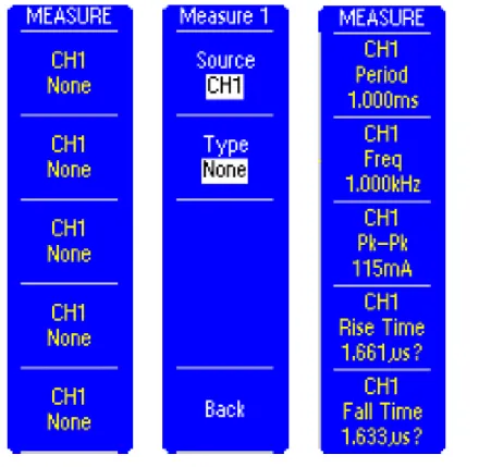
MEASURE Menu Function Controls
The MEASURE Menu Function Controls allow you to take predefined automated measurements of waveforms. There are 11 types of available measurements from which you can display up to five at a time.
Figure 8. MEASURE menu
Menu Option Description
Source You use this menu option to specify the source of a waveform as CH1 or CH2 for 2-channel oscilloscopes
Type You use this menu option to specify the type of measurement to be made for each source selection. You can select from 2 possible source selections in 2- channel oscilloscopes.
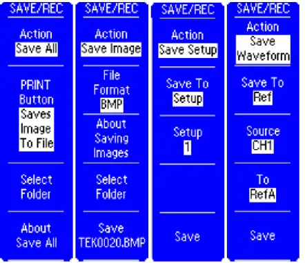
SAVE/RECALL Menu Function Controls
You use the SAVE/RECALL Menu Function Controls to save and recall up to 10 oscilloscope setups and 2 waveforms from non-volatile memory or to save and recall oscilloscope setups, display images and/or waveforms from a USB flash drive.
Figure 9: Save options for the SAVE/RECALL menu
Recall Waveform. Each action has a unique menu display. As a result, the menu options change according to the save and recall type that you select.
The Save All option configures the oscilloscope to save a display image, oscilloscope setup, and the waveform data for each activated channel and reference waveform in one folder on a USB flash drive. You can select various menu options for Save All feature.
Menu Option Description
Save All You use this menu option to save a
display image, oscilloscope setup, and the waveform data for each activated channel and reference waveform in one folder on a USB flash drive.
Button You use this menu option to configure the PRINT button to send screen image to printer or to save data to a USB flash drive.
Select
Folder You use this menu option to specify the USB flash drive folder where the files are to be saved
About Save
All You use this menu option to display the help information for Save All function
Save Image You use this menu option to save a
display image a USB flash drive.
File Format You use this menu option to set the
display image graphics file format. About Saving
Images You use this menu option to display the help information for Save Image function. Select
Folder You use this menu option to specify the USB flash drive folder where the display image file is to be saved.
Save You use this menu option to save the
display image to the automatically generated file name in the current USB flash drive folder.
Save Setup You use this menu option to save the
current oscilloscope setup to one of 10 non-volatile memory locations on the oscilloscope or to a USB flash drive
Save To You use this menu option to choose
whether the current oscilloscope setting is saved to a location in nonvolatile setup memory (Setup) or on a USB flash drive (File).
Setup You use this menu option to specify
Select
Folder You use this menu option to specify the USB flash drive folder where the setup file is to be saved.
Save You use this menu option to save the
display image to the automatically generated file name in the current USB flash drive folder.
Save
Waveform You use this menu option to save the specified waveform data to one of 2 non-volatile
memory locations on the oscilloscope or to a USB flash drive.
Save To You use this menu option to choose
whether the current oscilloscope setting is saved to a location in
nonvolatile reference memory (Ref) or on a USB flash drive (File).
Source You use this menu option to specify
which source waveform to save.
To RefX You use this menu option to specify
which nonvolatile reference memory location to save to.
Select
Folder You use this menu option to specify the USB flash drive folder where the waveform data file is to be saved
Save You use this menu option to save the
display image to the automatically generated file name in the current USB flash drive folder.
Recall Setup You use this menu option to recall a
saved oscilloscope setup from a nonvolatile memory location or from a USB flash drive.
Recall From You use this menu option to choose
whether the saved oscilloscope setting is recalled from a location in nonvolatile reference memory (Setup) or from a USB flash drive (File).
Setup You use this menu option to specify
which nonvolatile setup memory location to recall from.
Select File You use this menu option to specify the
USB flash drive folder where the setup file is to be recalled from.
Recall You use this menu option to recall the
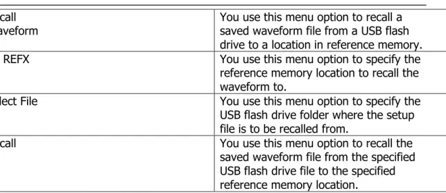
Recall
Waveform You use this menu option to recall a saved waveform file from a USB flash drive to a location in reference memory.
To REFX You use this menu option to specify the
reference memory location to recall the waveform to.
Select File You use this menu option to specify the
USB flash drive folder where the setup file is to be recalled from.
Recall You use this menu option to recall the
saved waveform file from the specified USB flash drive file to the specified reference memory location.
UTILITY Menu Function Controls
You use the UTILITY Menu Function Controls to access the various oscilloscope setup utility functions. You can use the UTILITY Menu Function Controls to check the system status, set up hard copy and communication utilities, perform self-calibration for the oscilloscope, and change the language used in the oscilloscopes.
To activate the UTILITY menu, push the UTILITY menu button.
Figure 11 shows the menu-based options for the UTILITY menu function controls. You can control each menu option by pushing the side-screen menu button next to the option.
Figure 11. UTILITY menu
Menu Option Description
System Status You use this menu option to check the
controls
Options You use this menu option to configure
the rear USB port, set up printing utilities, GPIB address, set date and time of the oscilloscopes internal clock and calendar, and view the error log generated during signal measurements.
Do Self Cal You use this menu option so that a
TDS1000B/TDS2000B oscilloscope performs self-calibration.
FileUtilities You use this menu option to navigate,
modify the contents of the USB flash drive.
Language You use this menu option to select the
display language for the side-screen menu from the various languages.
REF MENU Function Controls
You use the REF MENU Function Controls to turn on and off reference waveforms To activate the REF MENU, push the REF MENU button
Figure 12 shows the menu-based options for the REF MENU function controls. You can control each menu option by pushing the side-screen menu button next to the option.
Figure 12. REF MENU
Menu Option Description
Ref X You use this menu option to turn on
To activate the AUTORANGE menu, push the AUTORANGE menu button.
Figure 13 shows the menu-based options for the AUTORANGE menu function controls. You can control each menu option by pushing the side-screen menu button next to the option.
Figure 13. AUTORANGE menú
Menu Option Description
Autoranging You use this menu option to turn on or
off the AUTORANGE function. An LED light turns on adjacent to the
AUTORANGE button that indicates when the function is active.
Vertical and Horizontal You use this menu option to set up the AUTORANGE feature to track and
adjust both the vertical and horizontal axes.
Vertical Only You use this menu option to set up the
AUTORANGE feature to track and adjust only the vertical axis.
Horizontal Only You use this menu option to set up the AUTORANGE feature to track and adjust only the horizontal axis.
Undo Autoranging You use this menu option to recall the previous setup.
REVISIONES:
Revisión 1 Julio 2014 CCB/MPM