APPLICATION OF ULTRASONIC TECHNOLOGY
FOR NUCLEAR POWER PLANT INSPECTION AND MONITORING
PACS : 43.35.Zc
Authors: Jun Senboshi1; Michio Sato1; Shigeru Kanemoto1; Kiyoshi Iwata1; Kenji Tsuji2 Institution1: Toshiba Corporation Power Systems & Services Company
Address: 8, Shinsugita-cho, Isogo-ku, Yokohama City Code - City: 235-8523 Kanagawa prefecture Country: Japan
Tel: +81-45-770-2373 Fax: +81-45-770-2313
E-mail: jun.senboshi@toshiba.co.jp
Institution2: Chubu Electric Power Corporation Inc. Address: Kitasekiyama, 20-1 Midori-ku Nagoya City Code - City: 459-8522 Aichi prefecture Country: Japan
Tel: +81-70-5970-8115 Fax: +81-52-624-9207
ABSTRACT:
For reliable and long-term stable operation of nuclear power plants, inspection and maintenance are important. So, we develop ultrasonic-based non-destructive inspection systems, such as a peeling inspection system for pipe lining and a shape measuring system for a laser peening repairing system. The peeling inspection system can detect the peeling size of 10mm from outside of the pipe during plant operation. The shape measuring system can monitor a surface shape of a laser peening processed object within an accuracy of 0.1mm using ultrasonic generated by pulse laser irradiation. These examples contribute to plant maintenance and inspection efficiency. Also, they suggest that ultrasonic technology is suitable for a variety of plant inspection applications other than conventional non-destructive test applications.
1. INTRODUCTION
Since Nuclear Power Plant (NPP) operation began about 30 years ago in Japan, the maintenance and inspection of NPP is becoming more important. With the exception of the reactor pressure vessel which contains nuclear fuel and is exposed to high radiation, the essential structures of an NPP are the same as thos e of a conventional fossil power plant, being composed of dynamic equipment such as pumps, valves and static equipment such as pipes, heat exchangers. However, since NPP is usually operated continuously as a base load of power supply except annual plant outage period. SO, maintenance and inspection activity should be conducted during the period, it is important to increase inspection and maintenance efficiency so as to shorten the outage period and increase plant availability. Also, development of new inspection technology which can be applied during plant operation, which is called in-operation-inspection technology, is important for decreasing annual outage maintenance work and shortening the outage period. In order to contribute to the satisfaction of these needs, we are developing various kinds of inspection systems based on ultrasonic technology since they can be expected to be powerful non-destructive and in-operation inspection tools. In the present paper, we show several examples of ultrasonic systems which have characteristic application features different from those of conventional non-destructive application systems.
2. PIPE LINING INSPECTION SYSTEM
its damage in an early stage is necessary. In current procedure of pipe inspection in plant outage maintenance, inspection of the pipe lining is done by observing the inside of the pipe, after isolating, draining, detaching the pipe and removing seashells attached to the lining. If a defect is found, temporary repairing is done in the current maintenance period. Then proper and full-scale repairing is done in the next annual inspection period. Since the inspection range is wide and the inspection work is very troublesome, an efficient inspection tool, which can be applied without disassembling pipes and removing paints, is desired. Especially, the inspection tools which can be applied during plant operation period is highly desired. Hence we developed two kinds of inspection systems that could judge the condition of inside lining from the outside of piping using ultrasonic probes[1]. One system detects the echo of lining directly by using dual probes. The other system is based on a single EMAT (Electro-Magnetic Acoustic Transducer) [2], and detects lining peeling by analyzing the damping ratio of echo amplitude.
2.1 Dual Probe System
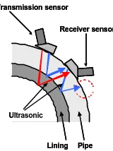
[image:2.596.242.322.323.430.2]Typical wall thickness of pipe (500A) in sea water system is 9.5mm and thickness of lining is from 2 to 3mm. Sound velocity in the pipe (carbon steel) is about 5950m/s and in the lining (polyethylene) is about 2000m/s. In the case of vertical detection, propagation time for ultrasonic to go and return in the pipe is about 3.2us and it is from 2 to 3us in the lining. In this case, damping of pipe bottom echo or multiple echoes overlap the lining echo. Therefore we propose a method in which the echo of lining is detected directly by using a dual probe system. The principle of the lining inspection system is shown in Fig. 1.
Fig.1 Principle of Dual Probe System
This system is composed of two sensors that have shoes to propagate angled ultrasonic. At first, the distance between two sensors and the angle of ultrasonic are optimized. The result is that, 45 degrees and 6mm are the suitable conditions. Using test piece that has circular defect of 10mm diameter, we tested the ability of this system. The equipment of the system is shown in Fig.2. The system has a jig for fixing the distance between two sensors, and magnetic wheels for attaching the sensor and moving it in a circumferential direction. The sensors are 6.5mm in diameter and center band is 5MHz. Fig.3 shows a typical raw waveform, the upper is the data taken at the location with peeling of lining, and the lower is the normal position. At the peeling position there is no characteristic wave after the pipe bottom echo. On the other hand, at the normal position 3us after the pipe bottom echo there is lining echo whose level is 1V at peak.
Fig.2 Dual Probe Lining Inspection System Fig.3 Example of the Raw Waveform
To judge the condition of lining automatically, signal processing is executed. Because thickness of the pipe and lining is known, the delay time of the lining echo from the pipe bottom
Transmission sensor
Ultrasonic
Pipe Lining
Receiver sensor Transmission sensor
Ultrasonic
Pipe Lining
Receiver sensor
Transducer Permanent Magnet
Test Piece (500A Pipe)
Transducer Permanent Magnet
Test Piece (500A Pipe)
”•— £• ”
- 2 - 1 0 1 2
0 2 4 6 8 1 0
ŠÔ •iƒÊs•
ƒŒƒxƒ‹
•
iV)
•³ •í•”
- 2 - 1 0 1 2
0 2 4 6 8 1 0
ŠÔ•iƒÊs•
ƒŒƒxƒ‹
•iV)
Pipe bottom echo
Echo level (V)
Echo level (V)
Peeling Position
Normal Position Time (us)
Time (us)
Lining echo ”•— £• ”
- 2 - 1 0 1 2
0 2 4 6 8 1 0
ŠÔ •iƒÊs•
ƒŒƒxƒ‹
•
iV)
•³ •í•”
- 2 - 1 0 1 2
0 2 4 6 8 1 0
ŠÔ•iƒÊs•
ƒŒƒxƒ‹
•iV)
Pipe bottom echo
Echo level (V)
Echo level (V)
Peeling Position
Normal Position Time (us)
Time (us)
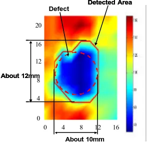
[image:2.596.128.481.581.720.2]echo can be calculated. In the present case, it is estimated to be from 2.1 to 3.1us. Then, signal level is integrated by absolute value from 2.1us after bottom echo, and the integrated value is compared with a threshold level. If the value is smaller than the threshold level, lining is supposed to be “peeling” or “damaged”. Scanning the sensor at the interval of 5mm, the ability of the system is tested. The threshold value can be determined by the echo measurement at normal piping area.Fig.4 shows the result of the test. The graph shows the distribution of integrated value according to the color map on the right-hand side in Fig.4.
Fig.4 Verification of Ability
Because normal positions have high value due to the effect of the lining echo, they are marked in red. And peeled positions are marked in blue. A red solid line shows the peeling area when the threshold value is determined to be half the value of the average value of 5 points in normal area. Though the actual peeled area’s shape is circular with diameter of 10mm, a result of the test shows a larger area. The problem is thought to be the threshold value. However, the purpose of this system is to “detect the peeling of the lining”, not to measure the size of peeling. So the system can identify the defect of the lining whose size is only 10mm at minimum.
2.2 Inspection System Using EMAT
It is troublesome to use a dual probe system, because the system needs contact medium. Hence, we developed another kind of inspection system using EMAT (Electro-Magnetic Acoustic Transducer). EMAT acts based on the theory of electro magnetic power, and so it can be used without contacting and contact medium. And one of the characteristics of EMAT is little absorption of energy compared with piezo electric transducer, and so the reverberation continues longer than in the case of a piezo electric transducer. Using this characteristic, lining inspection can be executed by evaluating the damping ratio of the ultrasonic. Fig.5 shows the principle of operation.
Fig.5 Principle of Lining Inspection System
(Using EMAT) Fig.6 Example of the Raw Waveform
In this system, EMAT generate a transverse wave perpendicularly from the surface of the pipe. If the lining is normal, a part of the echo arriving at the bottom of the pipe propagates toward the
0 4 8 12 16 20 16 12 8 4 0 About 10mm About 12mm Detected Area Defect
0 4 8 12 16 20 16 12 8 4 0 About 10mm About 12mm Detected Area Defect Pipe Lining EMAT Peeling
•iWater•AAir•j
Pipe
Lining
EMAT
Large damping ratio because of the power leaking to the lining
Pipe
Lining
EMAT Peeling
•iWater•AAir•j
Pipe
Lining
EMAT Peeling
•iWater•AAir•j
Pipe Lining EMAT Pipe Lining EMAT
Large damping ratio because of the power leaking to the lining
•³ •í• ” -2.5 - 2 -1.5 - 1 -0.5 0 0.5 1 1.5 2 2.5
0 10 20 30 40 50 60
Š Ô•iƒ Ês•j
ƒŒƒxƒ‹ • iV) 50mm”•—£• ” -2.5 - 2 -1.5 - 1 -0.5 0 0.5 1 1.5 2 2.5
0 10 20 30 40 50 60
Š Ô•iƒ Ês•j
ƒŒƒxƒ‹ • iV) 3.0V 4.0V 2.1V 3.8V
Echo level (V)
Peeling Position
Echo level (V)
Normal Position Time (us) Time (us) •³ •í• ” -2.5 - 2 -1.5 - 1 -0.5 0 0.5 1 1.5 2 2.5
0 10 20 30 40 50 60
Š Ô•iƒ Ês•j
ƒŒƒxƒ‹ • iV) 50mm”•—£• ” -2.5 - 2 -1.5 - 1 -0.5 0 0.5 1 1.5 2 2.5
0 10 20 30 40 50 60
Š Ô•iƒ Ês•j
ƒŒƒxƒ‹ • iV) 3.0V 4.0V 2.1V 3.8V
Echo level (V)
Peeling Position
Echo level (V)
Normal Position
Time (us)
[image:3.596.85.513.557.721.2]lining, and the rest reflects and propagates to the surface of the pipe. Because a part of the ultrasonic propagates to the lining, the power of the ultrasonic decreases every time it arrives at the bottom. The ratio of reflection is determined only based on the acoustic impedance. The acoustic impedance of the carbon steel is about 4.6*10^7, and the acoustic impedance of lining (polyethylene) is about 2.0*10^6, and so the ratio of reflection toward the surface is estimated to be about 84% for one reflection. On the other hand, in the case that lining is peeling and air or water is filled between lining and pipe, the echo arriving to the bottom is not reflected at all, because transverse wave does not propagate to air or water. Therefore by comparing the damping ratio, we can judge the condition of the lining. Fig.6 shows the typical raw waveform. Where lining is normal, the amplitude is 3.0V at t=0, and after six reflections, the amplitude decreases to 2.1V (30% decrease). On the other hand, at the peeling position, damping ratio is only 5%. Using this theory, we developed the inspection system shown in Fig.7. EMAT is attached to the guide rail with driving gear, and the gear can scan concyclic position automatically. The speed of the inspection is about 2 minutes for one round. The waveform is input to the personal computer and processed. Threshold level was input manually. The result is visualized on the computer into three levels, normal (blue), peeling (red) and caution (yellow) and shown in Fig.8. This system can detect a defect whose size is 20mm square. A test to determine whether a 10mm square defect could be detected was unsuccessful. It is supposed that the size of EMAT is 20mm square, and so the damping ratio is influenced by the normal position. In order to detect smaller exfoliation, it is necessary to miniaturize a sensor. Although the system is good for the pipe with usual rust resisting paint, application is difficult for the pipe with paint including zinc, because the sensitivity decreases remarkably. It is possible to adapt the dual probe system to inspect the pipe with paint including zinc. Thus, it is effective to use the properties of the two kinds of system.
. Fig.7 Inspection System Using EMAT
Fig.8 Visualization of the Inspection Result
3. Ultrasonic shape measuring system
In order to extend the NPP lifetime, it is necessary to apply appropriate preventive maintenance improvements. As one means of preventive maintenance, Toshiba developed laser peening maintenance technology which is for improvement of residual stress around welds[3], [4]. In the laser peening, it is important to determine the scanning region to be irradiates by the laser. But because the space where the equipment exists whose residual stress is to be improved is very narrow and subject to high dose of radioactivity, it is difficult to determine the region to be irradiated by the laser. If the weld is not identified, it takes a long time to operate laser peening. To reduce the operation time, the shape-measurement system is developed using the ultrasonic generated with laser processing. Because ultrasonic induced by laser has a sharp peak, a highly accurate measurement is expected. By the small piezo-electro transducer moving with laser processing head, picking up ultrasonic signal for measuring the time of flight between laser
Personal Computer Encoder
EMAT
Controller Oscilloscope
Pulsar / Receiver Guide Rail
A/D Converter•~‚Q
Personal Computer Encoder
EMAT
Controller Oscilloscope
Pulsar / Receiver Guide Rail
A/D Converter•~‚Q
longitude
Circumferential
50mm Exfoliation
40mm Exfoliation
30mm Exfoliation 20mm Exfoliation
•i• iDevelopment Figure of the Pipe•j•j
•i•iDistribution of t he circumferential•j•j
longitude
Circumferential
50mm Exfoliation
40mm Exfoliation
30mm Exfoliation 20mm Exfoliation
•i• iDevelopment Figure of the Pipe•j•j
irradiated point and sensor, and adding the information of the position of the head, the shape of irradiated object can be calculated. Using test piece with weld, test is conducted in a water tank. Fig.9 shows the schematic of the test. 2nd harmonic YAG Laser is used, iteration ratio is 10Hz, and pulse power is about 20mJ. According to the result of the test (shown in Fig.10), measuring accuracy is within 0.1mm, which is sufficient to detect the region of the weld.
Fig.9 Schematic of Test Fig.10 Result of the Test
4. CONCLUSION
We develop various inspection or measuring systems using ultrasonic. For example, a pipe lining inspection system is introduced. It can inspect defect of lining from outside of the pipe during plant operation. The resolution is circle of 10mm diameter at maximum and useful for efficient inspection. And the shape-measuring system which is used with laser processing is useful, too. The principle of these systems is very simple, but they have important practical advantages. The pump shaft vibration measuring system using ultrasonic from outside the pump casing was developed and is expected to be an effective monitoring tool for pumps[5]. To bring these kinds of systems into practical use, it is necessary to develop compact, easy-to-use and good measurement accuracy systems. The current digital processing technology makes it much easier to satisfy these requirements. The use of ultrasonic techniques will greatly improve inspection efficiency. We intend to develop the useful ultrasonic-based systems from now on.
Reference
[1] J. Senboshi et al. 2002 Annual Meeting of the AESJ Digest (II), 404 (2002) (in Japanese) [2] K. Tsuji et al. 2001 Annual Meeting of the AESJ Digest (II), 335 (2001) (in Japanese) [3] Y. Sano et al. Proc. 8th Int. Conf. On Nuclear Engineering (ICONE-8) 441(2000)
[4] Y. Sano et al. Proc. of Symposium on Shock Waves (Tsukuba, Japan) 53(2002) (in Japanese)
[5] K.osaki et al. Proc. 9th Int. Conf. On Nuclear Engineering (ICONE-9) 226(2001)
Laser System PZT
move•i2mm/s•j
Oscilloscope Tank
Head Test Piece (with Welds)
Ultrasonic 60 mm
45 mm
17 mm 22 mm 20 mm
13 mm
Laser System PZT
move•i2mm/s•j
Oscilloscope Tank
Head Test Piece (with Welds)
Ultrasonic
Laser System PZT
move•i2mm/s•j
Oscilloscope Tank
Head Test Piece (with Welds)
Ultrasonic 60 mm
45 mm
17 mm 22 mm 20 mm
13 mm 60 mm 45 mm
17 mm 22 mm 20 mm
13 mm
30 35 40 45 50 55 60 65 70
0 10 20 30 40
Propagation Length
•
i
mm
•
j
Move distance•imm•j Laser
Ultrasonic
Result Test Piece
30 35 40 45 50 55 60 65 70
0 10 20 30 40
Propagation Length
•
i
mm
•
j
Move distance•imm•j Laser
Ultrasonic