Preprint of the paper
"A Boundary Element Numerical Approach for Substation Grounding in a Two
Layer Earth Structure"
I. Colominas, J. Aneiros, F. Navarrina, M. Casteleiro (1997)
En "Advances in Computational Engineering Science", Sección: "Recent Developments in
Boundary Element Method", pp. 756--761; S.N. Atluri, G. Yagawa (Editors); Tech Science
Press, Atlanta, USA (ISBN: 0-96570001-0-0)
SUBSTATION GROUNDING IN A TWO LAYER EARTH STRUCTURE 3
IgnasiColominas, JuanAneiros, FermnNavarrinaand Manuel Casteleiro
Departamento deMeto dos Matematicos, Universidadde La Coru ~na
E.T.S. de Ingenierosde Caminos, Canales y Puertos
Campus deElvi ~na, 15192| La Coru ~na, SPAIN
SUMMARY
Analysisanddesignofsubstationgroundingrequirescomputingthedistributionofp otential
onthe earthsurface (for reasonsof human security) and the equivalent resistance of the earthing
system(for reasonsof equipmentprotection) when fault conditions o ccur (Sverak et al.,1981).
A newBoundaryElementapproachforthenumericalcomputationof substationgrounding
systems in nonuniform soils is presented in this pap er. The formulation is sp ecially derived for
two-layer soil mo dels, which are widely considered as adecquate for most practical cases. The
feasibility of this BEM approachis demonstrated by solving a real application problem, in which
accurateresults for the equivalent resistance and the p otential distributionon the ground surface
areobtained with acceptable computingrequirements.
INTRODUCTION
Severalmetho dsforgroundingdesignandcomputationhaveb eenprop osedinthelastthree
decades. Mostof themare foundedon semiempiricalworks or onthe basisof intuitive ideas,such
as sup erp osition of punctual current sources and error averaging (Hepp e,1979). Although these
techniques represented a signicant improvement in the area of earthing analysis, a numb er of
problemshaveb eenrep orted: applicabilitylimitedto very simplegroundingarrangementsof
elec-tro des in uniform soils, large computational requirements, unrealistic results when discretization
of conductors is increased, and uncertainty in the margin of error (Garrett and Pruitt,1985). In
the last years a Boundary Element formulation develop ed by the authors has allowed to identify
this family of primitive metho ds as the result of intro ducing suitable assumptions in the BEM
approach inorder toreduce computational cost forsp ecicchoices of the test and trial functions.
Furthermore, the anomalous asymptotic b ehaviour of this kind of metho ds could b e
mathemati-callyexplained,and sourcesof errorhaveb een p ointed out(Colominas,1995). On the otherhand,
thisBEM formulationhasb een succesfullyapplied(witha veryreasonable computationalcost) to
theanalysis of large groundingsystemsin electrical substations(Colominas et al.,1996).
The physical phenomena of fault currents dissipation into the earth can b e describ ed by
means of Maxwell's Electromagnetic Theory (Durand,1966). Constraining the analysis to the
obtention of the electrokinetic steady-state resp onse and neglecting the inner resistivity of the
earthingconductors, the 3D problemcan b e writtenas
div
=0;
=0
gradV in E;
t
nnnnnnnnnn n n n n E
=0 in 0
E
; V =V
0
in 0; V 0!0; if jxxxxxxxxxx
x x x
xj!1; (1)
where E is the earth, its conductivity tensor, 0
E
the earth surface,nnnnnnnnnnnnnn
E
its normal exterior unit
eld and 0 the electro de surface (Navarrina et al.,1992; Colominas,1995). The solution to this
3
Work partially supp orted by Power Companies \UNI
problemgivesthep otentialV andthecurrentdensityatanarbitraryp ointxxxxxxxxxxxwhentheelectro de
attainsa voltage V
0
(Ground Potential Rise or GPR) relative toa distant groundingp oint. Since
V and
are prop ortional to the GPR value, the normalized b oundary condition V
0
= 1 is not
restrictiveat all, and will b e used from here on.
Inmostofthemetho dsprop oseduptothismomentitisassumedthatforpracticalpurp oses
soil can b e considered homogeneous and isotropic. Thus, conductivity tensor is substituted by
a meassured apparent scalar conductivity (Sverak et al.,1981). In general, it is supp osed that
thisassumptiondo esnot intro ducesignicanterrorsif the soil is essentially uniform(horizontally
and vertically) up to a distance of approximately 3 to 5 times the diagonal dimension of the
grid, measured from its edge (ANSI/IEEE,1986). However, parameters that are involved in the
groundingdesign can change signicantly as soil conductivity varies through the substation site.
Therefore,it seems reasonable to seek for more accurate mo delsthat couldtake into account the
variation of soil conductivity in the surroundingsof theearthing system.
It must b e obviousat thisp oint thatmo delsdescribingall variations ofsoil conductivity in
thesurroundingsofasubstationwouldb e unaordable,fromb othtechnicalandeconomicalp oints
ofview. A morepractical(andstillquite realistic)approachtosituationswhereconductivityisnot
markedly uniform with depth consists of consideringthe earth stratied in a numb erof
horizon-tal layers, which appropriate thickness and apparent scalar conductivity must b e exp erimentally
obtained. In fact, it is widely accepted that two layer earth mo dels should b e sucient to obtain
go o ddesignsof earthingsystems in most practical cases (Sverak et al.,1981).
When the groundingelectro de is buried in the upp er layer, the mathematical problem (1)
canb e reduced tothe Neumann ExteriorProblem:
1V 1
=0 in E
1
; 1V
2
=0 in E
2 ;
dV 1 dn
=0 in 0
E
; V
1
=V
2
in 0
L ;
1
dV 1 dn
=
2 dV
2 dn
in 0
L
; V
1
=V
0
in 0; V
1
0!0 and V
2
0!0 if jxxxxxxxjxxxxxxx !1;
(2)
where E
1
and E
2
are the upp er and lower layers of the earth, 0
L
is the interface b etween them,
1
and
2
are the resp ective apparentscalar conductivities of b oth layers, and V
1
and V
2
are the
resp ective expressions of the p otential in each one of them (Tagg,1964; Aneiros,1996). Further
development in this pap er is restricted to the ab ove case. Of course, analogous results can b e
easilyobtained if the groundingsystemis buried in the lower layer of theearth (Aneiros,1996).
VARIATIONAL STATEMENT OF THE PROBLEM
In most of real electrical installations, the particular geometry of the grounding electro de
|a grid of interconnected bare cylindrical conductors, horizontally buried and supplemented by
a numb er of vertical ro ds, which ratio diameter/lenght uses to b e relatively small ( 10
03 )|
precludesthe obtention of analytical solutions. On the other hand,the use of standard numerical
techniques (such as Finite Dierences or Finite Elements) requires the discretization of domains
E 1
and E
2
, and the obtention of suciently accurate results would imply an extremely high (out
of range) computational eort. At this p oint, we remark that computation of p otential is only
required on 0
E
, and the equivalent resistance can b e easily obtained in terms of the leakage
current density =
t
n n n n n
nn
n n n n n n n
on the grounding electro de surface 0, b eing nnnnnnnnnn
n n n n
the normal exterior unit
eld to 0 (Colominas,1995). Therefore, we turn our attention to a Boundary Integral approach,
which will only require thediscretization of 0, andwill reduce the 3D problemto a 2D one.
If one further assumes that the earth surface 0
E
and the interface b etween the two soil
Theoryto (2) allowto express the p otential V 1
(xxxxxxxxxxx 1
) and V
2 (xxxxxxxxxxx
2
), at arbitrary p oints xxxxxxxxxxx
1 in E 1 and x x x x x xx x x x x x x x 2 in E 2
, in terms of the unknownleakage currentdensity (
), at any p oint
[ x ; y ; z
] on 0,
inthe integral form:
V 1
(xxxxxxxxxx x x x x 1 )= 1 4 1 ZZ 20 k 11
(xxxxxxxxxx
xx x x 1 ; )(
)d0; 8xxxxxxxxxx
x x x x 1 2E 1 ; V 2 (xxxxxxxxxx
x x x x 2 )= 1 4 1 ZZ 20 k 12
(xxxxxxxxxx
xx x x 2 ; )(
)d0; 8xxxxxxxxxx
x x x x 2 2E 2 ; (3)
b eing the weakly singularkernels
k 11
(xxxxxxxxxx x x x x 1 ; )= 1
r (xxxxxxxxxx x x x x 1 ;[ x ; y ; z ]) + 1
r (xxxxxxxxxx
xx x x 1 ;[ x ; y ;0 z ]) + 1 X i=1 h i
r (xxxxxxxxxx x x x x 1 ;[ x ; y
;2iH+
z ])
+
i
r (xxxxxxxxxx x x x x 1 ;[ x ; y
;2iH0
z ])
+
i
r (xxxxxxx x x x xx x x 1 ;[ x ; y
;02iH+
z ])
+
i
r (xxxxxxx x x x xx x x 1 ;[ x ; y
;02iH0
z ]) i ; k 12
(xxxxxxxxxxxxxx 2
;)=
1+
r (xxxxxxxxxxxxxx 2 ;[ x ; y ; z ]) + 1+
r (xxxxxxxxxxxxxx 2 ;[ x ; y ;0 z ]) + 1 X i=1 h
(1+)
i
r (xxxxxxxxxxxxxx 2
;[
x
;
y
;2iH+
z ])
+
(1+)
i
r (xxxxxxxxxxxxxx 2
;[
x
;
y
;2iH0
z ])
i
(4)
wherer (xxxxxxxxxx
xx
x
x;
)indicatesthedistanceb etweenp ointsxxxxxxxxxx
x x x x and
,H istheheigthofthe upp ersoillayer
andisarelationb etweentheconductivitiesofb othlayers: =(
1 0 2 )=( 1 + 2 )(Aneiros,1996).
Since the expression for p otential V
1 (xxxxxxxxxx
xx
x x 1
) in (3) holds on the earthing electro de surface 0,
theb oundary condition V
1
() =1; 820 leads to a Fredholm integralequation of the rst kind
on 0 with quasi-singular kernel k
11 ( ;
) , which solution is the unknownleakage current density
(Colominas,1995). Moreover, for all memb ers w () of a suitable class of test functions dened
on0, this problemcan b e writtenin the weaker variational form:
ZZ 20
w ()
1 4 1 ZZ 20 k 11
(; ) () d001
!
d0 = 0: (5)
Obviously,aBoundaryElementformulationseemstob etherightchoicetosolvevariational
statement(5). Thus,forgivensetsof 2Db oundaryelementsandtrial functionsdenedon0, b oth
the leakage current density and the grounding electro de surface can b e discretized
(Colomi-nas,1995). Now, for a given set of test functions dened on 0, variational form (5) is reduced to
asystem of linear equations,which co ecientsmatrix is full. However, since computationof each
termrequires an extremelyhigh number of evaluations of the kernel k
11 ( ;
) and double
integra-tionona2Ddomain(Aneiros,1996),it isnecessarytointro ducesome additionalsimplicationsin
theBEM approachto decrease the computationalcost (Colominas et al.,1996).
APPROXIMATED 1D BOUNDARY ELEMENT FORMULATION
Considering the real geometry of grounding systems in most of electrical substations, one
canassumethatthe leakage currentdensity isconstantaround thecrosssection of the cylindrical
electro de (Navarrina et al.,1992). This hyp othesis of circumferentialuniformity is widely used in
mostof the practicalmetho ds relatedin theliterature (ANSI/IEEE,1986).
Thus, let L b e the whole set of axial lines of the buried conductors,
b the orthogonal
projection over the bar axis of a given generic p oint 20, (
b
) the electro de diameter, and (b
Intheseterms,andb eing k 11
(xxxx;xxxxxxxxxx ) andk
12
(xxxx;xxxxxxxxxx ) theaverageof kernels(4)aroundthecrosssection
at b
, we canwrite expressions (3)as
b V 1
(xxxxxxxxxxxxxx 1 )= 1 4 1 Z b 2L k 11 (xxxxxxxxxxxxxx;
b
)b (
b
) dL;8xxxxxxxxxxxxxx
1 2E 1 ; b V 2
(xxxxxxxxxxxxxx 2 )= 1 4 1 Z b 2L k 12 (xxxxxxxxxxx;xxx
b
)b (
b
) dL;8xxxxxxxxxxxxxx
2
2E
2
: (6)
Now, since the leakage current is not really uniform around the cross section, variational
state-ment (5) will not hold anymore. However, if we restrict the class of trial functions to those with
circumferentialuniformity,(5) results in
1 4 1 Z b 2L (b ) b w (b ) " Z b 2L ( b ) k 11 (b ; b
)b(
b )dL # dL= Z b 2L (b ) b w (b
)dL; (7)
which must hold for all memb ers w (bb
) of a suitable class of test functions dened on L, b eing
k 11 (b ; b
) the average of kernel k
11 (b ; b
) in (4) around the cross sections at b
and b (Colomi-nas,1995).
Now, for given sets of 1D b oundary elements and trial functions dened on L, the whole
set of axial lines of the buried conductors L and the unknown leakage current density b can b e
discretized. Then, for a given set of test functions dened on L, variational form (7) is reduced
to a system of linear equations (Colominas et al.,1996; Aneiros,1996). The matrix of co ecients
of this approximated 1D problem is still full. However, on a regular basis we can say that the
computational cost has b een drastically reduced, since the actual discretization (1D) for a given
problem will b e much simpler than b efore (2D). Furthermore, suitable unexp ensive
approxima-tions(Colominas,1995) canb e intro duced toevaluatethe averagedkernels
k
11
(bx ;
b ), k 12
(bx ;
b ) and k 11 (b ; b
). Nevertheless,computationof remainingintegralsisnot obvious,andthecost of
numeri-calintegrationis stilloutof rangedue totheill-conditioning ofintegrands. Suitablearrangements
inthenal expressionsof thematrixco ecients allowto usehighlyecientanalytical integration
techniques that have b een derived by the authors in cases of earthing systems in uniform soils
(Colominaset al.,1996), in order toreduce the computational cost.
This BEM approach has b een implemented in the CAD system for grounding grids of
electrical installations develop ed by the authors in recent years (Casteleiro et al.,1994). It is
imp ortanttonoticethatthetotalcomputingeortrequiredinsomecasesisvery high,particularly
inthoseinwhichconductivitiesofsoillayersareverydierent(jj1). Thefactisthattherateof
convergenceof averagedkernels
k 11 (1;1), k 12
(1;1)and
k
11
(1;1)isverylowwhenjj1,whichmakes
necessaryto computean extremelylarge numb erof terms in order to obtainaccurate results.
APPLICATION TO A REAL CASE
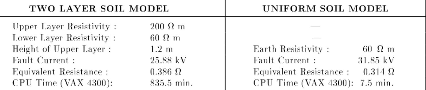
This formulation has b een applied to a real case: the E.R.Barbera substation grounding
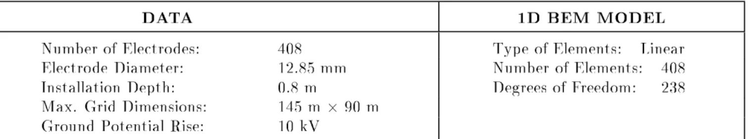
(closetothecity of BarcelonainSpain). Thecharacteristicsandnumericalmo delaresummarized
inTable 1. The plan is presented in gure 1. Results(such as the equivalent resistance, the fault
current and p otential proles along dierent lines) obtained with this BEM approach by using a
two layer soil mo del are compared with those obtained by using an uniform soil mo del (gure 1
and table 2). It can b e shown that results are noticeably dierent, and the design parameters of
theearthing systemcomputed fromthem may signicantly vary. Therefore,it will b e essential to
analyze grounding systems with this new BEM technique, in cases in which the conductivity of
Upp er LayerResistivity : 200 m |
LowerLayerResistivity : 60m |
Height ofUpp er Layer: 1.2 m Earth Resistivity : 60 m
Fault Current : 25.88kV FaultCurrent : 31.85kV
Equivalent Resistance : 0.386 Equivalent Resistance: 0.314
CPU Time(VAX 4300): 835.5min. CPU Time (VAX 4300): 7.5min.
Table2.|E.R.Barb eraSubstation: Characteristics andResultsbyusingdierentsoilmo dels
CONCLUSIONS
ABoundaryElementformulationfortheanalysisofsubstationgroundingsystemsemb edded
in layered soils has b een derived. This approach has b een applied to the practical case of an
earthing system in an equivalent two layer soil. Some reasonable assumptions allow to reduce a
general2D BEM approachto an approximated1D version, accordingto sp eciccharacteristicsof
these installations in practice. By means of the scheme of analytical integration techniques that
hasb een recently derivedby theauthorsforthecase of groundingsystemsinuniformsoils,highly
accurateresultscanb e obtainedinreal problems. At present,thestudyof larger installationsstill
requires an imp ortant computing eort due to the large numb er of terms of integral kernels that
it is necessary to evaluate in order to obtain accurate results. However, the application of new
techniquesthatare b eing derivedby theauthors,will allowtoaccelerate theirrateof convergence
andreduce the actual computationalcost.
REFERENCES
Aneiros J.M. (1996): Una Formulacion Numerica para Calculo y Dise ~no de Tomas de Tierra de
Sub estacionesElectricascon Mo delos deTerreno deDos Capas. ResearchRep ort. E.T.S.I.C.C.P.
ANSI/IEEE Std.80(1986): Guide for Safety in AC Substation Grounding. IEEEInc., New York
CasteleiroM. et al. (1994): Memoriay Manual de Usuariodel Sistema TOTBEM paraCalculo y
Dise ~no Asistido p orOrdenadordeTomas de Tierra de InstalacionesElectricas. E.T.S.I.C.C.P.
Colominas I. (1995): Calculo y Dise ~no p or Ordenador de Tomas de Tierra en Instalaciones El
ec-tricas: Una FormulacionNumericabasada en el MEC. Ph.D.Thesis. E.T.S.I.C.C.P.
ColominasI.,NavarrinaF.and Casteleiro M.(1996): \A Boundary ElementNumericalApproach
forEarthing Grid Computation",Submitted to the Int. J. Num. Meth. Engng.
DurandE. (1966):
Electrostatique. Masson Ed., Paris
GarretD.L. and Pruitt J.G. (1985): \ProblemsEncounteredwith the APM of Analyzing
Substa-tionGroundingSystems",IEEE Trans. P.A.S.,Vol. 104, No. 12, 4006{4023
Hepp eR.J.(1979): \Computationofp otentialatsurfaceab oveanenergizedgridorotherelectro de,
allowing fornon-uniformcurrent distribution",IEEE Trans. P.A.S.,Vol. 98, No. 12, 1978{1988
NavarrinaF.,ColominasI.andCasteleiroM.(1992): \AnalyticalIntegrationTechniquesfor
Earth-ingGridComputationbyBEM",Int. Co. Num. Meth. Engng. Ap. Sci.,CIMNEPub.,1197{1206
SundeE.D. (1968): Earth conductioneects in transmissionsystems. McMillanEd., New York
SverakJ.G.etal.(1981): \SafeSubstationsGrounding",IEEETrans. P.A.S.,Vol. 100,4281{4290
Numb erof Electro des: 408 Typ eof Elements: Linear
Electro de Diameter: 12.85mm Numb erof Elements: 408
Installation Depth: 0.8 m Degrees of Freedom: 238
Max. GridDimensions: 145 m290m
GroundPotential Rise: 10kV
Table 1.|E.R.Barb eraSubstation: CharacteristicsandNumericalMo del
1 Unit = 10 m
0.
25.
50.
75.
100.
125.
Distance (m)
0.0
2.0
4.0
6.0
8.0
10.0
Potential (kV)
0.
25.
50.
75.
100.
125.
150.
175.
Distance (m)
0.0
2.0
4.0
6.0
8.0
10.0
Potential (kV)
Fig.1.|E.R.Barb eraSubstation: PlanoftheGroundingGridandPotentialprolesalongtwodierentlines(results
obtainedbyusing anuniformsoilmo delareindicatedwithdiscontinuousline,andthoseobtainedbyusing