Secure Communication System Using Chaotic Signals
Sistema de comunicación seguro usando señales caóticas
I. Campos-Cantón Facultad de Ciencias
Universidad Autónoma de San Luis Potosí, México E-mail: icamposu@galia.fc.aslp.mx
E. Campos-Cantón
Departamento de Físico Matemáticas, CIEP-FI Universidad Autónoma de San Luis Potosí, México
E-mail: ecamp@uaslp.mx
J.S. Murguía-Ibarra Departamento de Físico Matemáticas Universidad Autónoma de San Luis Potosí, México
E-mail: ondeleto@uaslp.mx
M.E. Chavira-Rodríguez Departamento de Físico Matemáticas Universidad Autónoma de San Luis Potosí, México
E-mail: mchavira@uaslp.mx
(Recibido: agosto de 2006: aceptado: enero de 2008)
Abstract
We pres ent ex per i men tal re sults of a cha otic com mu ni ca tion sys tem that em ploys di rect mod u la tion, with the Chua’s cha otic os cil la tor as a core of the trans mit ter block. The main re sult is that its pos si ble to re cover the in for ma tion sig nal if we mod u late over one state of os cil la tor and trans mit a dif fer ent state, avoid ing a cor re la tion be tween the in for ma tion sig nal and the cha otic carrier.
Keywords: Cha otic com mu ni ca tion, cha otic car rier, chaos syn chro ni za tion, trans mit ter block, re ceiver block.
Resumen
Se presentan resul tados expe ri men tales de un sistema de comu ni ca ción caótico que emplea modu la ción directa, con el osci lador caótico de Chua como corazón del bloque trans misor. El prin cipal obje tivo es que es posible recu perar la señal de infor -ma ción al modular un estado del osci lador y trans mitir un estado dife rente, evitando una corre la ción entre la señal de infor ma ción y la porta dora caótica.
Descrip tores: Comu ni ca ción caótica, porta dora caótica, sincro ni za ción de caos, bloque trans misor, bloque receptor.
Intro duc tion
De spite the fact that there ex ist sev eral con ven tional
tech niques, we can con sider cha otic mask, di rect mod -u la tion, and bi nary mod -u la tion. a) Cha otic mask (Cuomo et al., 1993; Kocarev et al., 1992), where the in -for ma tion sig nal is added to the cha otic car rier in the trans mit ter block, and the re ceiver block just takes the cha otic car rier away from the re ceiver sig nal in or der to re cover the in for ma tion sig nal. b) For di rect mod u la tion (Halle et al., 1993; Urías, 1999; Volkovskii et al., 1993), we re fer to the ac tion of add ing the in for ma tion sig nal to the dy nam ics of the cha otic os cil la tor in the trans -mit ter block, whereas an in verse op er a tion is car ried out on the re ceiver block to re cover the in for ma tion sig -nal. c) In bi nary mod u la tion (Dedieu et al., 1993; Parlitz et al., 1992), the in for ma tion sig nal is cod i fied by two dis -tinct cha otic sys tems, and it is re cov ered by de tect ing syn chro ni za tion with sim i lar cor re spond ing sys tems in the re ceiver block. One tar get is to im prove or pro pose new schemes (Dmitriev A.S. et al., 2003; Larson et al., 2006) of this kind of com mu n i ca tion systems.
How ever, some prob lems have been pre sented when cha otic os cil la tors are used to mod u late in for ma tion sig nals. For in stance, for a cer tain range of am pli -tudes and fre quen cies of the in for ma tion sig nal there ex ist a high cor re la tion be tween the cha otic car rier sig -nal and the in for ma tion sig -nal, as long as de struc tion of cha otic be hav ior is pre sented, re spec tively. These two prob lems avoid the main purpose of “masking” in for m -a tion sign-al using ch-aos.
In this work, we pro pose a pro ce dure to avoid cor re -la tion be tween in for ma tion sig nal and cha otic car rier sig nal, and the pos si bil ity to re cover the in for ma tion sig nal. The phys i cal im ple men ta tion of this com mu ni -ca tion sys tem is based on Chua’s cir cuit un der the same spirit that in (Corron et al., 1997).
The struc ture of this pa per is as fol lows. The section called cha otic com mu ni ca tion sys tem de scribes the gen eral the ory of this com mu ni ca tion sys tem. The
fol low ing section con tains the phys i cal im ple men ta tion of such com mu ni ca tion sys tem. Fi nally, the ex per -i men tal re sults and con clu s-ions are pre sented.
Chaotic Commu ni ca tion System
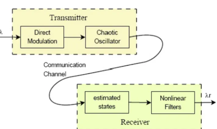
Fig ure 1 shows the ba sic func tional blocks of our cha -otic com mu ni ca tion sys tem. The main blocks are the trans mit ter and the re ceiver, re spec tively. It is pos si ble to con sider a com mu ni ca tion sys tem with the fol low -ing char ac ter is tics:
a) In the trans mit ter, we mod u late one state of the sys -tem with the in for ma tion sig nal and use a dif fer ent state as a cha otic car rier. With this, we mask the in -for ma tion sig nal and avoid cor re la tion be tween these sig nals.
b) In the re ceiver, we re con struct oth ers states that were not trans mit ted us ing a con ver gence strat egy; fur ther more, we use a non-lin eal fil ters to re con -struct the in for ma tion sig nal.
The com po nents of our cha otic com mu ni ca tion sys -tem are de scribed be low.
The Trans mitter
Ba si cally, the trans mit ter cou ples the in for ma tion sig -nal to the com mu ni ca tion chan nel. It is com prised of a cha otic os cil la tor, which is mod u lated by the in for ma -tion sig nal us ing di rect mod u la -tion. Con sid er ing a third or der os cil la tor, the trans mit ter has the form
+
& ( , , ) ( ) ( , , ), & ( , , ),
& ( , , )
x u x y z t u x y z y v x y z
z w w y z
= +
= =
0 l 1
.
(1)
The pa ram e ter l( )t is a pre scribed func tion of time that rep re sents the in for ma tion to be com mu ni cated. The set of equa tions 1, which rep re sents the trans mit ter, has to sat isfy the fol low ing re quire ments.
1. To make use of one state to mod u late and the other one as a car rier. In our case l is the state mod u lated, whereas the y state is trans mit ted.
2. The ac cept able val ues of l( )t need to sat isfy the con -di tion | ( )|lt <e. The con stant eis se lected such that the os cil la tor in al ways op er ates in a cha otic re gime.
In our ap proach, the car rier is y(t), in con trast to (Corron et al., 1997), where the car rier was x(t) and the sub sys tem formed by (y,z) is in de pend ent of the pa ram -e t-er l.
The Receiver
It is well known that the main func tion of the re ceiver is to ex tract the in for ma tion sig nal from the de graded ver sion of the trans mit ted sig nal com ing from the chan nel. From fig ure 1, the re ceiver con sists of two blocks, where the first one is use ful to re con struct the states that were not trans mit ted. The way to re con -struct states de pends strongly of the cha otic os cil la tor em ployed. In the next sec tion is pre sented the ap -proach to es ti mate the non-trans mit ted states us ing the Chua’s os cil la tor. The orig i nal sig nals x and z are re -con structed from sig nal, as long as xr and zr by means of
cha otic syn chro ni za tion at the re ceiv ing end. The sec -ond block is uti lized to es ti mate the in for ma tion sig nal. The na ive ap proach to re cover l( )t would be to use the es ti ma tion
lr
r r r
r r
x u x y z u x y z = & - ( , , )
( , , ) 0
1
. (2)
How ever, if we use equa tion (2) to im ple ment the de -mod u lator, sin gu lar i ties are en coun tered when ever u1 =( , ,x y zr r)=0. In or der to avoid this sit u a tion we use a low pass fil ter.
Al ter na tively to es ti mate equa tion (2), we used the un cou pled pair of first or der fil ters
& ( , , ) ( ),
p u x y z x p
k
r r
0 0
0
= + - (3)
& ( , , ) .
p u x y z p
k
r r
1 1
1
= - (4)
In the fil ters (3)-(4), the con stant k>0 works as a tun ing pa ram e ter. Its main func tion al ity is to re duce res i dues of the car rier in the out put of the re ceiver. Con se -quently, the in for ma tion sig nal is es ti mated as
$ ( ) /
lr = x p- 0 p1, where the pa ram e ters p0 and p1 are the out puts of the fil ters (3)-(4). This sig nal lris fur ther
passed through the low-pass fil ter
t lf&f = -l l$ f. (5)
Sum ma riz ing, the re ceiver block con sists of a sub -sys tem to es ti mate the vari able states xr and zr, that is driven by the in com ing car rier y, which was gen er ated by the trans mit ter and fol lowed by the fil ters (3)-(5). The de mod u lated sig nal is lf, and the quan ti ties k and
tf are tun ing pa ram e ters of the re ceiver.
Physical Imple men ta tion
The phys i cal im ple men ta tion of this com mu ni ca tion sys tem is based on a cha otic elec tric cir cuit that does not in volve an a log mul ti pli ca tion, and it is a very han dy and cheap elec tric sys tem. It uses only re sis -tors, ca pac i -tors, di odes and op er a tional am pli fi ers as we will see.
The Trans mitter
Fig ure 2 shows the elec tronic cir cuit of the trans mit ter block. It is worth to note that the Chua’s os cil la tor is the core of the trans mit ter, where the com po nent val -ues em ployed for its con struc tion are set ting to have a cha otic be hav ior, and the value of po ten ti om e ter was fixed at 1.8kW. For more in for ma tion of Chua’s cir cuit see (Chua et al., 1992).
The math e matic model of the trans mit ter block is de scribed by the fol low ing set of equa tions:
& ( ) ,
V G G
C V
G C V
G
C V C I
m m m x 1 1 1 1 2 1 1 1
= - + + + - (6)
& ,
V G
C V
G
C V C IL
2 2 1 2 2 2 1
= - - (7)
where V V1, 2, and IL are the cor re spond ing states, and , Gm =1/R1, G=1/Potl, C C1, 2 and L are pa ram e ters of
the sys tem. Ac cord ing to our model (1), x V= 1, y V= 2
and z=IL. Here, the di rect mod u la tion is ap plied to the node V1, the in for ma tion sig nal Vm is in jected to the os -cil la tor by the re sis tor R1, and is trans mit ted the state V2. With this will avoid cor re la tion be tween the in for
-ma tion sig nal Vm and the cha otic car rier V2.
The Receiver
In the re ceiver block, the prob lem is how we can es ti -mate the non-trans mit ted states us ing just one state. As we said, the V2 state is the cha otic car rier and it is em ployed to es ti mate the states V1 and IL. To achieve the es ti ma tion of the non-trans mit ted states V1 and IL, we use equa tions V1' and I
L
' to ob tain the es ti mated states and as fol low
V C
G V V GIL
1 2
2 2
1
' & ' ,
= + + (9)
I
L V d L
'
=1
ò
2 t. (10)Fig ure 3 shows the es ti ma tor block to es ti mate states V1' and I
L
'. This es ti ma tor is the re al iza tion of equa tions 9 and 10.
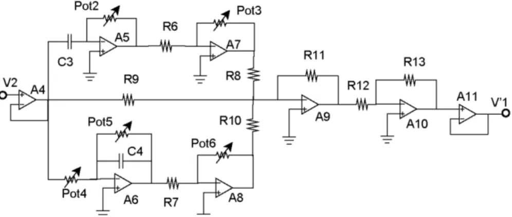
In fig ure 4 is shown the elec tri cal cir cuit di a gram to im ple ment the es ti ma tor block. This sub sys tem is formed for one in te gra tor, one differentiator and one ad -der cir cuits. The val ues ad justed of the po ten ti om eters were Pot2 = 390 W, Pot3 = 4.4 kW, Pot4 = 390 W, Pot5 = 3.9 kW and Pot6 = 3.6 kW. These val ues of the po ten ti om eters were tun ing to work prop erly with the fre -quency of the cha otic car rier sig nal.
In or der to re cover the in for ma tion sig nal, we need to use the equa tion. There fore, the in for ma tion sig nal can be re cov ered as fol lows
V C
G V
G G
G V
G
G V G I
m m
m
m m m
x
= 1 - + - +
1 1 2
1
& ( ) . (11)
Figure 2. The elec tronic circuit of the trans mitter block. The compo nent values employed are R1 =10kW , R2 =R3 =220W,
R4 =750W, R5 =1 2. W, Pot1 5= kW,C1 =10nF,C2 =100nF,
L1 =18mH. The diodes D1 and D2 are 1N914, and the oper
-a tion-al -ampli fiers -are TL-082.
Figure 3. Block diagram of the circuit to esti mate the states V1 and IL.
This cir cuit es ti mates the state V1' us ing the state V2. The com po nent val ues em ployed are
R1 =10kW, R6 =R7 =1kW,
R8 =R9 =R10 =R11 =R12 =R13 =10W, Pot2 3 4 6, , , =10kW,
Pot5 100= kW.
C3 =C4 =100nF and the op er a tional am pli fi ers are TL-082.
In fig ure 5 is shown the re cover in for ma tion block. The de vice la beled as Rx is a neg a tive non lin ear re sis -tive and is shown in the trans mit ter block, see fig ure 2. The val ues of the po ten ti om eters and were ad justed to 1.9 kW and 1.71 kW, re spec tively.
The el e ment la beled as Rx is an iden ti cal Chua’s di -ode, which is showed in the trans mit ter cir cuit (fig ure 2). The com po nent val ues em ployed to im ple ment the non-lin ear of the re ceiver block
R24 =R25 =R26=R31 =R32 =12kW, R33 =R34 =R35 =10W,
Pot8 9 10, = kW,
C6 =C7 =10nF and the op er a tional am pli fi ers are TL-082.
Results and Conclu sions
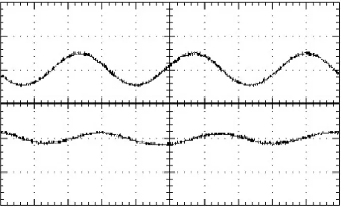
Three dif fer ent sig nals were con sid ered as in for ma tion sig nal Vm, and we use cou ple wire trans mis sion to trans mit all sig nals. The first in for ma tion sig nal was a sim ple sine func tion Vm =Asinwt, with am pli tude A=0 5. V and an gu lar fre quency w=2pf f( =3kHz). This sig nal is shown in fig ure 6 (top sig nal). Fol low ing our ap proach, in the re ceiver block we have three states (V V I', ', ' )
L
1 2 . Fig ure 7 shows the pro jec tion on the (V V, ')
1 1 plane, the re ceiver vari able V1
' against its trans -mit ter coun ter part V1. This graph in di cates
syn chr o ni za tion be tween these two sig nals, de spite the fact that both cir cuits are run ning cha ot i cally. The re cov ered in for ma tion sig nal is shown in fig ure 6 (bot tom sig nal). The at ten u a tion and de lay of the re con -structed sig nal are in tro duced by the fil ters used for its re con struc tion.
Figure 5. Nonlinear filter to recover the infor ma tion signal
Figure 6. The top signal is the first infor ma tion signal and the bottom signal is the recov ered infor ma tion signal Vm
'
Figure 7. Projec tion on the (V V, ')
1 1 plane. The hori zontal
axis repre sents the state V1, whereas the vertical axis
The re sults of cor re la tion be tween the in for ma tion sig -nal and the cha otic car rier are shown in fig ure 8. Fig ure 8 shows the in for ma tion sig nal (A), the mod u lated state V1(B), and the cha otic car rier V2(C), re spec tively. We can ob serve that there is no cor re la tion be tween the sig nals of fig ure 8 (A) and (C), whereas in sig nals of fig -ure 10 (A) and (B) is ev i dent a cor re la tion.
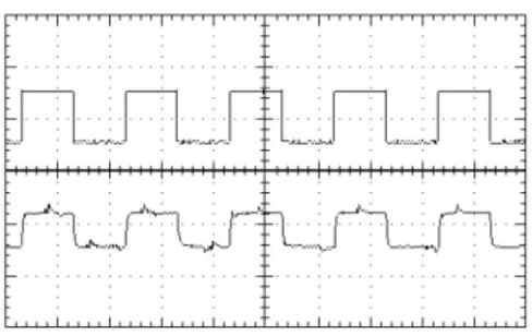
The sec ond in for ma tion sig nal an a lyzed was a square sig nal with am pli tude equals to 1 Vpp, and a fre -quency of 100 Hz. The re sults ob tained with this sig nal are shown in Fig ure 9; the top sig nal is Vm, whereas the bot tom sig nal is the re cov ered in for ma tion sig nal Vm'. The smooth en ing of the tran si tions in the de mod u lated sig nal is in tro duced by the fil ters.
Fi nally, we con sider as an in for ma tion sig nal Vm a mu sic sig nal, ob tained from the sound card of the PC. Fig ure 10 shows a seg ment of this sig nal (top), and the cor re spond ing de mod u lated sig nal (bot tom). The mu -sic was re cov ered very well.
In con clu sion, a method of cha otic com mu ni ca tion us ing di rect mod u la tion was pro posed here, and a prac ti cal ex per i men tal im ple men ta tion of this com mu ni ca tion sys tem was re al ized. We could re cover the in for ma tion sig nal us ing this method, where cor re la tion be -tween the in for ma tion sig nal and the cha otic car rier was avoided. It is clear that Chua’s cha otic os cil la tor al lowed mak ing a prac ti cal eval u a tion of the di rect mod -u la tion ap proach to se c-ure com m-u ni ca tions.
Fi nally, de spite we do not con sider the ef fect of the noise in the ex per i ments, the pos si bil ity to con sider the noise will be ex am ined in an other pub li ca tion.
Acknow ledg ments
ECC re ceived fi nan cial sup port from FAI-UASLP un der con tract C07-FAI-11-38.74, and JSM re ceived fi nan cial sup port from PROMEP and FAI-UASLP.
Figure 8. (A) The first infor ma tion signal Vm=Asinwt, where A=1 Vpp and w=2pf f( =15Hz). (B) The modu lated
state V1 state. (C) The chaotic carrier, V2.
Figure 9. A square signal as an infor ma tion signal Vm ,
with ampli tude equals to 1 Vpp and a frequency of 100Hz, (top signal), and recov ered infor ma tion
signal Vm
' (bottom signal).
Figure 10. The last infor ma tion signal Vm (top, music
signal), and recov ered infor ma tion signal Vm
'
Refe rences
Chua L.O., Kocarev L., Eckert K., Itoh M. Expe ri mental Chaos Synchro ni za tion in Chua’s Circuit. Int. J. Bifur. & chaos, (12):705-708.1992.
Corron N.J., Hahs D.W. A New Approach to Commu ni ca -tions Using Chaotic Signals. IEEE, Trans. Circuits System, I(44):373-382. 1997.
Cuomo K.M., Oppen heim A.V., Stro gatz S.H. Robust ness and Signal Reco very in a Synchro nized Chaotic System. Int. J. Bifur. and Chaos, (3):1629-1638. 1993.
Dedieu H., Kennedy M.P., Hasler M. Chaotic Shift Keying: Modu la tion and Demo du la tion of Chaotic Carrier Using Self-Synchro ni za tion Chua’s Circuit. IEEE Trans. Circuits Syst. II(40):634-642.1993.
Dmitriev A.S., Kyar ginsky B.Y., Panas A.I., Starkov S.O. Expe ri ments on Ultra Wide band Direct Chaotic Infor ma -tion Trans mis sion in Micro wave Band. Int. J. Bifur. & Chaos, (13):1495-1507. 2003.
Halle K.S., Wu C.W., Itoh M., Chua L.O. Spread Spec trum Commu ni ca tion Through Modu la tion of Chaos. Int. J. of Bifur. and Chaos, (3):469-477. 1993.
Itho M., Mura kami V. New Commu ni ca tion System Via Chaotic Synchro ni za tions and Modu la tions. IEICE Trans. Funda ment., E78A:285-290. 1995.
Larson-Lawrence L.J.M., Tsim ring L. Digital Commu ni ca tions Using Chaos and Nonli near Dynamics. Edt. Springer. 2006. Kocarev V, Halle K.S., Eckert K., Chua L.O., Parlitz V. Expe ri
-mental Demons tra tion of Secure Commu ni ca tions Via Chaotic Synchro ni za tion. Int. J. Bifur. and Chaos, (2):709 713. 1992.
Mayb hate A., Amritkar R.E., Kulkarni D.R. Esti ma tion of Initial Condi tions and Secure Commu ni ca tion. Int. J. Bifur. and Chaos, (13):3079-3084. 2003.
Parlitz V, Chua L.O, Kocarev V, Halle K., Shang A. Trans mis -sion of Digital Signals by Chaotic Synchro ni za tion. Int. J. Bifur. and Chaos, (2):973-977. 1992.
Sush chik M.M., Rulkov N.F., Larsen L., Tsim ring L.S., Abar banel H.D.I., Yan K., Volkovskii A.R. Chaotic Pulse Posi -tion Modu la -tion: a Robust Method of Commu ni ca ting with Chaos. IEEE Comm. Lett., (4):128-130. 2000.
Urías J. Analog Modu la tion and Demo du la tion of a Chaotic Osci llator. Rev. Mex. de Fís., (45):331-335. 1999.
Volkovskii A.R., Rulkov N.F. Synchro nous Chaotic Response of a Nonli near Osci llator System as a Prin ciple for the Detec tion of the Infor ma tion Compo nent of Chaos. Tech. Phys. Lett., (19):97-99. 1993.
About the authors
Isaac Campos-Cantón. Received the Master’s degree in elec trical engi nee ring from the School of Engi nee ring, UNAM in 1997, in this moment he is working in his docto rate at IICO, UASLP, his current research is on the elec tronic circuits
with nonli near beha vior and complex networks.Eric Campos-Cantón. Es licen ciado en elec tró nica por la Facultad de
Cien cias, UASLP, maestro en inge niería eléc trica por la IICOFacultad de Inge niería, UASLP y doctor encien cias aApli -cadas por el IICO-Facultad de Cien cias, UASLP.
Eric Campos-Cantón. Received the Master’s degree in elec trical engi nee ring in 1999 and the Ph. D. degree in Applied Science in 2003 from Univer sidad Autó noma de San Luis Potosí. Since then, he has been a Professor at the same Univer sity. He
contri buted in the book Digital Commu ni ca tions using Chaos and Nonli near Dyna mics (Springer, 2006). His research inte
-rests include dyna mical systems with nonli near beha vior and its appli ca tions to engi nee ring and science.
José Salomé Murguía-Ibarra. Obtained his B.Sc. degree in 1998 in Elec tronic Engi neer with a specia li za tion in Digital Systems from the Auto no mous Univer sity of San Luis Potosí (AUSLP). He got his M.Sc. degree in Elec trical Engi nee ring and his PhD degree in Applied Sciences in the AUSLP, in 1999 and 2003, respec ti vely. Since January 2003, he has been ProfessorResear cher of the PhysicsMathe ma tical Depart ment of the AUSLP. He is actually a member of the Resear -chers National System, and his research inte rests include signal proces sing, wavelet analysis and applied mathe ma tics.