Electrical power distribution systems
3.1 General discussion
As the medical profession is increasingly more dependent upon complex electrical equipment and instrumentation for patient care and facility operation, the proper design of electrical power distribution systems in health care facilities is most important. The proper selection of the system components, and their arrangement, is critical to providing the health care facility with reliable, safe, and economical electric power.
Total or partial loss of electric power in a health care facility can cause acute operational problems (i.e., power loss to the lighting systems makes it impossible to perform vital medical tasks such as dispensing medicine, performing surgical procedures, or performing precise medical laboratory work). The loss of power to tissue, bone, or blood bank refrigerators can leave the health care facility without these vital resources. Power loss to electrical life support equipment such as heart pumps, medical vacuum pumps, dialysis machines, and ventilators can be fatal. Clearly, continuity of high-quality electric power should be the most important factor in the design of the electrical distribution systems for health care facilities.
Safety is another particularly important design criteria for health care facilities because a) Medical personnel frequently come into contact with electrical apparatus in their
daily routines.
b) Patients often are very vulnerable to electrical shock hazard because of their weakened condition, because of drugs or anesthesia administered, and/or because of their unconscious state. Electrical shocks that would not severely affect a healthy person could be fatal to a patient.
c) It is necessary for maintenance personnel in health care facilities to come in daily or weekly contact with electrical distribution equipment for routine maintenance or minor system additions and renovations.
Maintainability, expandability, and flexibility are also very important design criteria. Hospitals are under increasing financial pressures, and the ability to spend capital dollars wisely is crucial to their overall health. Investments in electrical infrastructure that support maintainability, expandability, and flexibility can significantly contribute to the financial viability of the health care organization. Electrical systems should allow needed preventive and failure maintenance to be done with little disruption to the operations of the hospital. New technologies are always being presented to the medical profession. These new technologies may require additional power, additional support systems, and often, new building areas. The ability to expand, and the flexibility to change, the distribution system to meet these new technologies are also very important design criteria.
overcurrent protection and coordination, electrical equipment, and installation and system arrangements.
3.2 Systems planning
Basic overall systems planning is the first and probably one of the most important phases in the overall design of an electrical power distribution system for a health care facility. During this phase, preliminary design data is gathered from administrators and staff of the health care facility, the local utility, and authorities having jurisdiction (AHJs) over electrical construction. All relevant national, state, and local codes, and facility design guidelines, should be reviewed. Two national codes having a major affect on health care power distribution design are:
— National Electrical Code® (NEC®) (NFPA 70)1 — NFPA 99, Standard for Health Care Facilities
In addition, electrical engineers should examine the architectural plans and existing site conditions from an electrical system perspective to determine potential problems and needs. The following subclauses will discuss some of the issues that should be addressed during the system planning phase of the design.
3.2.1 Consult with the project architect
A vital step in systems planning is early and ongoing coordination with the project architect. A first step is giving input to, and providing review of, the preliminary floor plan and schematics from an electrical design perspective. The electrical engineer should be sure to provide informed input to the planners and architects to ensure that the spaces provided will support the needs of the electrical systems. Examples of early coordination input include the following:
a) Provide adequate electrical and communication equipment room sizes
b) Orient the spaces to minimize electrical costs and to support future maintenance and expansion of the system
c) Provide adequate space in other certain areas having significant electrical equipment such as radiology suites or computer rooms
d) Ensure electrical rooms have adequate accessibility to the electrical equipment and devices so as to prevent restrictions on equipment removal and installation after initial construction is complete
e) Avoid locating “wet areas” near or above electrical or communication rooms f) Telephone/communications/data room size and location requirements need to
provide needed working or maintenance clearances
g) Provide adequate ventilation, cooling, and/or exhaust needs of electrical/ communication rooms
h) Provide space for routing of needed raceways, busways, and cable trays
i) Plan space for any temporary installation and use of large electrical testing apparatus such as load banks that may be needed in the future
Electrical designers should locate electrical equipment in rooms dedicated to such equipment. Codes then prohibit piping, ductwork, or any architectural appurtenances not serving that room or space (and only those rooms) from passing over or within working clearances of the equipment. Accordingly, the designer needs to work closely with the architect and mechanical engineer to ensure proper placement and utilization of electrical spaces. A common problem to beware of is the location of toilet rooms or mechanical equipment rooms directly over electrical spaces. Planning these rooms in this way will result in the installation of “forbidden” piping or equipment over the electrical gear.
3.2.2 Consult with the health care facility staff
Engineers designing electrical distribution systems should also consult with various representatives of the facility early in the process.
a) Facility users. The designer must know the specific functions to be performed in the facility. This information is needed in order to apply the proper codes and to weigh the importance of reliability, quality of electrical power, safety, and economy. For example, the reliability designed into a distribution system serving a hospital that specializes in open-heart surgery would not be justified in an outpatient clinic with no surgical functions. In addition, a facility that extensively utilizes computerized diagnostic, patient records, and accounting systems would require a higher quality of electric power.
The facility will usually have some plans for the future. These plans could be in the form of preliminary ideas or may be well documented. Itis essential that these plans be analyzed and well incorporated into the electrical system design. Depending on budget constraints, additional capacity should at least “set up” the distribution system for future expansion(s).
b) Financial and budget representatives; information. The designer must know the financial expectations of the administrators. The administrators will start a project with a budget that will need to be held to in order to allow the business to operate successfully once the project is complete. This budget must be considered in all phases of design in order to assure satisfaction. Such economic constraints, however, do not allow critical needs to be ignored. If the budget is unrealistic, the designer shall call this to the attention of the hospital administrator as soon as possible.
Health care administrators are concerned with both the one-time capital costs of the projects and the yearly operating costs of the installed systems. Designers should therefore provide information on both the initial capital requirements and the relative operating expenses of different possible design options. The administration may decide it is better to increase the capital outlay to reduce the facility’s ongoing expenses.
availability of replacement parts, prevalence of one vendor over another in an existing building, pricing, and levels of support locally available. Whatever the reason, the designer should keep these preferences in mind throughout the system design. If the designer feels that these preferences are unjustified, he or she should review them with the staff during the design process; and if necessary, with the administrators as to the cost, safety, and/or code implications of the staff’s preference.
The skill, number (relative to facility size), and 24-hour availability of the facility’s maintenance and operations personnel are an important design consideration. For example, if the maintenance personnel for a particular facility does not include skilled electricians, the designer may consider specifying a system that requires minimum maintenance, is relatively simple to operate, or is automated and supervised from a competently staffed remote location (in real time), compared to a system that requires much more maintenance and/or more ongoing operator involvement. Where the skill level of the maintenance staff may compromise the necessary design of the electrical systems to meet the other goals, then electrical designers should consider designs that are simpler and require less operator intervention.
d) Future expansion of the facility.
3.2.3 Determine the basic loads and demand data
The designer should begin to tabulate preliminary load data. The preliminary architectural floor plans can be used effectively by superimposing load data on them. The floor plans should show major equipment loads, block loads based on square footage, and any future loads or buildings that the power system should be designed to accommodate. Always allow for load growth even beyond the defined plans for future expansions. See Chapter 2 of this recommended practice for guidance on determining these loads.
In the initial stages of planning, exact load data will seldom be known. However, the designer can estimate probable loads based on existing, similar, health care facilities. Helpful data is listed in Chapter 2 of this recommended practice and in IEEE Std 241™ (IEEE Gray Book™) (Chapters 2 and 16). Also refer to the electrical load data in the
handbooks of the American Society of Heating, Refrigerating, and Air-Conditioning Engineers (ASHRAE). The sum of the electrical ratings of each piece of equipment will provide a total “connected load.” Since most equipment will operate at less than full load, and some intermittently, the “connected demand” on the power source is always less than the “connected load.” Standard definitions for these load combinations have been devised and defined in Chapter 2 of this recommended practice, IEEE Std 141™ (IEEE Red Book™), and the NEC. The projected electrical system’s heat loads should always be reviewed with the mechanical engineer to ensure that the air-conditioning system is sized properly for that load.
3.2.4 Consult with the local electric power company
company will be interested in the size of the load demand, the projected power factor, the load factor, and the need for backup service. They will also be interested in the plans for on-site generation, the size of the largest motors and the method of starting (for voltage drop reasons), and any unusual demands or service requirements.
The designer should clearly determine the following:
a) Are there any limitations on the size of load the utility can service? b) Will there be any “up-front” charges for supplying power to the facility?
c) What type of service does the utility plan to provide? What are their requirements? What is the service history?
1) Single phase (two or three wire) or three phase (three or four wire) 2) Voltage level
3) One circuit or two circuits 4) Overhead or underground services
5) Termination details for their cables and/or overhead lines (phase rotation, circuit labeling, etc.)
6) Space requirements for their equipment (including landscaping, set backs, roadways, etc.)
7) Metering requirements, details, and space requirements. Also are there any loads needing separate meters, etc.?
8) Outage histories of proposed services to evaluate reliability (also confirm “outage” definitions as used in those histories)
d) What components of the electrical service will the owner be required to furnish? 1) Primary conduit(s)
2) Primary trenching, backfill, and “markers” 3) Primary cables
4) Transformer(s) 5) Transformer vault(s) 6) Concrete pad(s)
7) Metering and metering conduit
8) Surge arresters and transient voltage surge suppression
9) Environmental protection (noise abatement from transformers, oil spill systems, fire protection, etc.)
10) What is the physical “break line” between utility-supplied and owner-supplied equipment (e.g., property line, last pole, underground vault)? e) What are the utility’s billing rates and rate structure? Following are some general
considerations (see Chapter 2 for more details).
g) What will be the maximum and minimum voltage to be expected at their power supply point? (Will voltage regulating equipment be required?) If possible, get a copy of the voltage meter chart.
h) May internal generation, if it will exist in the proposed system, be allowed to operate in parallel with the utility? If yes, what are their requirements on relaying, control, metering, and communications?
i) What is the maximum short-circuit current available? Ask them to supply three-phase and single-three-phase-to-ground duties (with the respective X/R ratios) for today’s system, and as expected 5 years into the future.
j) What are their protective device coordination requirements?
Please note that the utility is not required to follow the NEC in providing an electrical service. The utility does normally, however, follow the National Electrical Safety Code™
(NESC™) (Accredited Standards Committee C2). The designer in any case should stress
the utility’s responsibility to work with the designer in order to provide the health care facility with safe, reliable service.
3.2.5 Reliability issues
Life support and high-value continuity uses may merit the redundancy offered by secondary-selective systems, radial systems with secondary voltage transfer switches, and other similar systems. The system designer should plan to perform the increased engineering analysis that accompanies these higher reliability systems, and compare the value of improved continuity of service, reduction in false outages, and the improved level of equipment protection—all balanced against cost and simplicity of operation. IEEE Std 493™(IEEE Gold Book™) describes the reliability of radial systems and other systems.
3.2.6 Consult with the local authorities having jurisdiction over new electrical construction
The designer should also meet with the local AHJs over electrical construction and discuss their special requirements and interpretations of the relevant codes. The designer should incorporate the effects of these interpretations during the system planning stage. The local authorities can also provide input on any local natural phenomena that may affect the electrical design, such as the presence of frequent violent electrical storms, seismic conditions, or a corrosive environment. These authorities include the electrical inspector, fire marshal (chief), Department of Health (city, state, and/or federal), Occupational Safety and Health Administration (OSHA), insurance underwriters, etc.
3.3 Electrical power systems basics
a) The numerous governing codes and standards
b) The use of complex and electrically sensitive medical equipment
c) Most importantly, the fact that patients and medical personnel must be guarded against electrical hazards
3.3.1 Power sources
Generally, the electric utility provides power to the facility. Codes require the owner to also supply an alternate power source, such as an on-site generator set, uninterruptible power supply (UPS), or battery/inverter system. However, when the normal source consists of an on-site power generator(s), the alternate power source required can be another power generator unit or the electric utility. A battery/inverter system can be applied as the principal alternate power source for nursing homes, residential custodial care facilities, and other health care facilities provided they meet the conditions outlined in the NEC, Article 517, and NFPA 99. Many facilities will require a UPS for computing centers, communication systems, or other critical, sensitive loads.
Additional data pertaining to generator units and batteries can be found in Chapter 5 of this recommended practice, as well as the NEC (Articles 517 and 700), NFPA 99, NFPA 110, NFPA 111, and IEEE Std 446™(IEEE Orange Book™).
3.3.2 Distribution circuits
Distribution systems for health care facilities are basically divide into two categories—the normal (“non-essential”) electrical system and the essential electrical system. The normal source supplies both systems, but the essential electrical system can transfer to the alternate power supply whenever the normal power source experiences a power failure.
a) Non-essential electrical system. The non-essential electrical system consists of distribution equipment and circuits that supply electrical power from the normal power supply to loads that are not deemed essential to life safety, or the effective and essential operation of the health care facility.
b) Essential electrical system. The essential electrical system consists of the transfer equipment, distribution equipment, and circuits required to assure continuity of electrical service to those loads deemed as essential to life safety, critical patient care, and the effective operation of the health care facility. NFPA 99 and the NEC cover these topics in great detail and should be carefully reviewed. The information given here summarizes much of that data.
also defines the types of electrical loads to be served by the life safety branch and the critical branch. The NEC allows the designer to install “other equipment and devices necessary for the effective operation of the hospital” on the critical branch of the emergency system. This gives some flexibility in tailoring the design to the specific needs of the health care facility. The designer should use his/her experience, hospital staff input, and good engineering judgment in applying this article to the design.
The equipment system consists primarily of three-phase distribution equipment and circuits, including automatic, delayed-automatic, or manual transfer devices to serve equipment loads essential to the effective operation of the facility as defined by NFPA 99 and NEC Article 517. In addition, the Joint Commission, formerly the Joint Commission on Accreditation of Healthcare Organizations (JCAHO), requires that if a hospital has a fire pump it must be connected to the equipment system via an automatic transfer switch (ATS).
For nursing homes and residential custodial care facilities, which provide care requiring electromechanical sustenance and/or surgical or invasive treatment requiring general anesthesia, the essential electrical system also consists of two systems, but these two systems are the emergency system and the critical system. The emergency system in these cases is limited to those loads defined for the life safety branch for hospitals, plus sufficient illumination to exit ways in dining and recreation areas. These emergency system circuits are required to be installed separately and independent of nonemergency circuits and equipment. The NFPA standards require that this emergency system branch be designed to permit automatic restoration of electrical power within 10 seconds of power interruption. The critical system is limited to critical receptacles, task illumination, and equipment necessary for the effective operation of the facility.
For other health care facilities (excluding hospitals, nursing homes, and residential custodial care facilities where the facility administers inhalation anesthetics or requires electromechanical life support devices), the essential electrical system consists of one system supplying a limited amount of lighting and power considered essential for life safety and orderly cessation of procedure whenever normal electrical service is interrupted for any reason. The type of system selected should be appropriate for the medical procedures performed in the facility.
NFPA 99 requires the emergency power source, typically standby generators, to meet the requirements defined for Type I, Type II, and Type III installations as noted in NFPA 99. These “type” designations define maximum start times, maximum run times, etc.
3.4 Voltage considerations
satisfactory voltage will be supplied to all utilization equipment under all conditions of operation (i.e., including large motor starting). Refer to IEEE Std 141 (IEEE Red Book)
and IEEE Std 241 (IEEE Gray Book) for a detailed discussion of voltage.
3.4.1 Select system voltages
The best voltage levels for a particular system will depend on the utility voltage available, the size of the health care facility, the loads served, expansion requirements, the building layout, voltage regulation requirements, and cost.
Typically, a large health care facility will be supplied power at a medium voltage level from the utility, and it will be stepped-down to either 480Y/277 V or 208Y/120 V for utilization. Either 480 V or 208 V can be used to supply mechanical equipment (chillers, fans, pumps, etc.), medical equipment (radiology, medical air pumps, etc.), and other support equipment such as laboratory equipment and kitchen equipment. If 480 V is present, however, it offers a number of advantages for certain applications, particularly for larger loads. In general, 480 V systems can serve the same amount load using much smaller conductors, frequently requiring fewer circuits and smaller feeders.
The use of 277 V lighting in lieu of 120 V in large health care facilities is common. The application of 277 V lighting in hospitals, however, differs from other commercial facilities because of the requirement for the four divisions of the electrical system (normal, critical branch, life safety branch, and the equipment system). Depending on other equipment requirements, applying 277 V lighting may increase the number of 480Y/ 277 V panels on each floor and/or in each electrical room. There is no general rule on when to apply 277 V lighting. Each individual application should be analyzed to determine its feasibility. Typical benefits of 277 V lighting include reduced system losses, reduced number of branch circuits for lighting, reduced sizes of power conductors, reduced heat gains on the air conditioning system due to power losses, and segregation of the harmonics of the electronic ballasts in luminaires from the medical equipment operating at 208Y/120 V. Once the designer has chosen the preferred operating voltage for the lighting systems, it should be used consistently throughout the facility. It is dangerous to operating personnel to mix voltages on similar type lighting systems.
3.4.2 Nominal voltage
Once engineers select the nominal utilization voltages for the system, they should carefully check all medical equipment to assure proper application. If the equipment will be new, it should be ordered to one of the planned utilization voltages. If this is not possible, then a “buck/boost,” autotransformer or standard two-winding transformers will be needed to supply rated voltage to the equipment. A common misapplication includes the use of nominally rated 230 V motors installed on a 208 V system.
400Y/230V, or 380Y/230 V, they should be recognized as 400Y/230 V systems and are acceptable tolerances.
Imaging equipment is available in a variety of single-phase and three-phase voltages. Make sure to know the exact voltage requirements and tolerances of the equipment from the manufacturer’s data to properly plan for its installation. Because of their operating characteristics (low load factor, low power factor, and/or high surges), power distribution systems dedicated to these pieces of equipment may be appropriate.
In general be aware that transformer regulation may result in a voltage drop of 2.5% to 5%. Therefore, to maintain acceptable voltage at the utilization equipment, the voltage drop in the wiring should be limited to less than 2.5%.
3.4.3 Voltage variation and disturbances
Variations in the sinusoidal voltage waveform can be caused by many different types of power system disturbances. Transient overvoltages are caused by lightning, capacitor switching, fault switching, welding, arcing grounds, brush-type motors, or switching of inductive loads, such as motors, radiology equipment, etc. Nonlinear loads such as switch-mode power supplies, ballasts, and adjustable speed drives are generators of harmonics that can cause serious neutral overloading, transformer overloading, and interference problems. See IEEE Std 1100™(IEEE Emerald Book™). Momentary total loss of voltage
can be the result of utility switching, fault clearing operations, some transient voltage arrester operations, or equipment failure. Transient voltage suppression is dealt with in IEEE Std 141™ (IEEE Red Book™), IEEE Std 142™(IEEE Green Book™), and IEEE Std 241™(IEEE Gray Book™), and the IEEE Surge Protection Standards Collection (C62) [B8].2 See also the requirements of NFPA 780.
Many kinds of voltage protection, regulating, and conditioning equipment is available on the market. Surge arresters, voltage regulators, transient voltage surge suppressors, shielded isolation transformers, voltage regulators, power conditioners, UPSs, or combinations of this equipment can be applied to solve voltage variation problems. The choice of which equipment to apply depends on the nature of the voltage variations and the characteristics of the equipment to be protected.
a) Surge arresters, voltage regulators, and transient voltage surge suppressors are designed to remove temporary overvoltages from the power system for protection of distribution and utilization equipment.
b) Shielded isolation transformers are effective in rejecting certain types of transients. They will, however, not provide a clean, noise-free ground. IEEE Std 142 (IEEE Green Book) and IEEE Std 1100 (IEEE Emerald Book) are excellent references on transformer and sensitive load grounding.
c) Voltage regulators or constant voltage transformers are designed to tightly control output voltage (for many cycles) regardless of variations of input voltage. The range of input voltage for which the output voltage will remain regulated is generally –10% to +20%, or –15% to +15% of nominal. In addition to input
voltage range, other considerations in applying a voltage regulator are regulator load sensitivity, load compatibility, power factor, energy efficiency, and electrical isolation.
d) Power conditioners generally combine regulation, isolation, and/or transient suppression into one package.
e) Static (electronic) UPSs provide a constant voltage with standby battery capacity for power failures and short outages. Static UPSs may, however, be a source of electrical noise/harmonics themselves and may not always deliver a clean sinusoidal waveform unless they are specified carefully.
Rotary (mechanical/electrical) UPSs are available to provide a pure sinusoidal waveform. Further, there is a rotary UPS configuration that is always online and that relies on a diesel engine for backup. This type of UPS does not require large battery banks.
Harmonic currents can be controlled or suppressed through the use of delta-connected transformers, harmonic filters, isolation transformers, etc. IEEE Std 141 (IEEE Red Book)
deals with this subject in great detail.
The first step toward properly solving a voltage variation problem is to properly diagnose the problem. Only when the problem is properly defined is it possible to select the proper voltage regulating, protection, or conditioning equipment. Unless the exact problem is known, an engineer may specify equipment that amplifies the problem, rather than reduces or eliminates the problem.
3.4.4 Voltage problem diagnosis
In an existing facility, engineers can use a high-accuracy power analyzer to diagnose voltage problems. These tools can observe a portion of the electrical system over a period of time with voltage variations and quality recorded including magnitude, duration of the variation, the per-unit harmonic content, and the time of occurrence. This data can then be matched with medical equipment operational logs, problem logs, and/or maintenance trouble reports to determine any possible correlations.
In new facilities, the distribution equipment can be designed to include solid-state metering to provide continuous monitoring. These monitors can provide detailed power quality information in addition to load data.
3.4.5 High transient loads
Radiology and some other machines draw very high momentary currents during an exposure. These machines therefore require a low-impedance source to assure that the voltage drop is within acceptable limits, usually 3% to 5%. An x-ray tube will experience loss of life and equipment malfunction if it does not have the proper voltage regulation. Note, however, that standard voltage regulators applied on radiology equipment feeders may not improve regulation because the pulse width of the equipment may be less than the response time of the regulator.
Voltage fluctuations and dips caused by motor starting within the hospital should be maintained within the limits dictated by the utility and by industry standards for computerized equipment. Normally, systems can accomplish this goal if the motors have reduced voltage starters or soft starters on large motors, or if separate transformers supply the large motors. The designer should carefully study the application of these starters, or separate transformers, to minimize system voltage drops at reasonable costs.
3.5 Current considerations
The load equipment in a health care facility will determine the full-load current requirements in a health care power system. However, the power sources, together with contributions from rotating equipment such as motors will determine the short-circuit current requirements of the system.
The impedance of the circuits and equipment from the source to the point of fault and the X/R ratio of the system will limit the short-circuit current that may flow during a fault to the point of the fault. The fault current will not necessarily be directly related to the power demand of the system.
In most health care facilities, the fault-current contribution will differ in magnitude and decay rate between the normal and the alternate power sources. This can occur when
a) The normal power source is from a utility having a high-fault current capability, and the service entrance point is removed by several transformations and transmission circuits, from the utility generation sources.
b) The alternate power supply consists of a relatively low kilovoltampere on-site generator, or generators, and relatively short-distribution circuits between the alternate power supply and essential electrical power circuitry.
Thus for a fault occurring within the essential electrical power system, the fault-current magnitude from the normal power source would be relatively large and have a slow decay rate. A fault under the same fault conditions when served by the alternate power source would be relatively small and have a fast decay rate. These factors should be taken into account when selecting and setting protective devices since the essential electrical system can be supplied power from either source.
of coordination achieved, and calculate the voltage dips of impact loads such as motor starting, etc. Refer to IEEE Std 141 (IEEE Red Book), IEEE Std 241 (IEEE Gray Book),
IEEE Std 242 (IEEE Buff Book), and IEEE Std 393™ to obtain information on these
fundamentals.
3.6 Grounding
The word grounding is commonly used in electrical power work to cover both “equipment grounding” and “system grounding.” These and other terms used when discussing this topic are defined in the NEC and IEEE Std 142 (IEEE Green Book). These definitions should be quite familiar to obtain a better understanding of grounding principles.
In health care facilities, both the system and equipment are grounded. In addition, codes require special grounding requirements for those subsystems and equipment involved in patient care areas, operating rooms (ORs), anesthetizing locations, and special environments as presented in Chapter 4 of this recommended practice, the NEC, and NFPA 99.
3.6.1 Equipment grounding
Equipment grounding is the interconnection and bonding (grounding) of nonelectrical conducting material that either encloses, or is adjacent to, electrical power conducting components. Its purpose is to reduce electrical shock hazards; to provide freedom from fire hazards; and to minimize damage to equipment from component overheating caused by overcurrents, arcs, or bolted faults. To achieve these safety goals, engineers need to design and ensure the proper installation of a sufficiently low-impedance path to ground-fault currents. For ac systems, the (return) ground current will flow through the lowest impedance path, not the lowest resistance path as in dc systems. The lowest ground-impedance path will be a path close to the power conductors, such as a ground conductor installed with the power conductors and/or the metal raceway enclosing the power conductors (i.e., the conduit, housing of busway).
Furthermore, to maintain the lowest ground-current impedance, junctions and terminations must be properly installed. Metal joints should make good contact to avoid sparking during fault conditions. Adequate connections between equipment ground buses and/or housings and metal raceways should be provided. In addition, size the ground return circuit components (conductors, terminations, etc.) to carry the available ground-fault current for all types of ground-fault conditions and durations “permitted” by the overcurrent protection system (i.e., the ground-fault current may be 12 000 A or more).
3.6.2 System grounding
System grounding relates to the type of grounding applied to the electrical system. The basic reasons for system grounding are the following:
— To limit the differences of electrical potential between all noninsulated conducting objects in a local area.
— To limit overvoltages appearing on the system under various fault conditions.
Several methods for achieving system grounding are as follows. The preferred method for health care facilities is solid neutral grounding, since the system neutral is generally readily available. This will avoid the special system operating precautions required when employing other grounding methods. See also IEEE Std 142 (IEEE Green Book).
a) Selection of system grounding points. The NEC requires the engineer to solidly ground the system at each voltage level to achieve the advantages of neutral grounding in all parts of the system. Each voltage level may be grounded at the neutral lead of a generator; power transformer bank; or in rare instances, neutral deriving grounding transformer.
When two or more sources serve a given point, each source should have a grounded neutral point since the bus-tie circuit may be open. Refer to IEEE Std 242 (IEEE Buff Book) and to NEMA PB 2.2 for special techniques of system neutral grounding of double-ended substations.
b) Neutral circuit arrangements. After selecting the grounding method, the engineer will need to consider how many source generator(s) or transformer neutral(s), or both, will be used for grounding, and whether to use
1) An independent ground for each neutral, or 2) A neutral bus with single ground connection.
c) Medium-voltage source neutral(s). The medium-voltage portion of the power system most often consists of a three-phase, three-wire system where the neutral is not used as a circuit conductor. IEEE Std 141 (IEEE Red Book) extensively covers the advantages and disadvantages of various medium-voltage grounding methods as well as design conditions for each method.
d) Low-voltage source neutral(s). Health care facilities usually have three-phase, four-wire system using the neutral conductor as a circuit conductor for their low voltage system. Thus, the source’s neutral should be solidly grounded to permit neutral loading as well as meet the requirements of the NEC.
Where the power supply consists of services that are dual fed in a common enclosure or grouped together in separate enclosures and employ a nonswitched (solid) secondary tie, the common neutral conductor can be effectively grounded at one point. Where the power supply for the health care facility consists of a normal and an alternate power supply, at least one of the power supplies, usually normal, is considered the service and its neutral(s) will need to be effectively grounded. If the normal and alternate power supply is not
WARNING
Note that in an ungrounded system, a fault condition can, in certain instances, lead to system resonance that causes an extreme overvoltage to be imposed on the system. This overvoltage can be sufficient in magnitude to create severe shock hazard as well as cause electrical equipment failure due to insulation breakdown. For these and other
electrically connected, then both power supply neutrals will have to be effectively grounded.
3.6.3 System and load characteristics
The type of grounding system and the arrangement of system and equipment grounding conductors will affect the service continuity. Engineers should design grounding conductors and connections so that objectionable stray neutral currents will not exist and ground-fault currents will flow in low-impedance, predictable paths to protect people from electrical shock and to assure proper operation of the circuit protective equipment.
Where systems serve phase-to-neutral loads, codes require them to be solidly grounded. However, 600 V and 480 V systems supplying only phase-to-phase loads may be solidly grounded, high-resistance grounded, or ungrounded. High-resistance grounded systems may provide a higher degree of service continuity than solidly grounded systems and might be useful in serving phase-to-phase loads requiring very high reliability. Any such system, however, needs to be carefully monitored to detect phase-to-ground faults early enough so that the fault(s) can be isolated and repaired promptly. Do not use ungrounded systems since they may experience overvoltages due to resonance conditions, or “neutral” shifts occurring during a ground-fault condition. For safety reasons, provide only solidly grounded systems below 600 V.
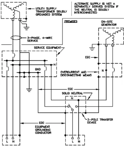
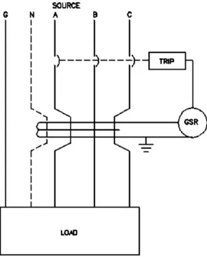
When the alternate power supply [generator(s) or separate utility service] and its wiring system electrically interconnect with the normal power supply by the neutral or phase conductors, then the NEC does not consider the alternate power supply to be a separately derived system. Thus, its neutral is cannot be grounded. In this case, only the normal power supply neutral can be grounded as shown in Figure 3-1. This requirement will prevent objectionable neutral load currents from flowing in the system ground conductors. Note that the equipment grounding conductor defined as EGC in Figure 3-1 is still required; thus the generator neutral must be insulated from the machine frame.
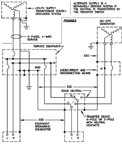
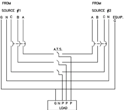
When the alternate power supply [generator(s) or separate utility service] and its wiring system are not electrically interconnected with the normal power supply wiring system either by the neutral or phase conductors, or both, then the NEC considers the alternate power supply to be a separately derived system. In this case, the alternate power supply neutral must be grounded [in addition to the neutral(s) of the normal power supply]. Figure 3-2 depicts a system where the neutral and phase conductors between the alternate and normal power supply wiring systems are not electrically interconnected by the use of a four-pole transfer device. Since the neutral conductors are isolated between the two power systems, grounding of the generator neutral will not provide an alternate path (to ground) for load currents on the normal power source.
3.7 System protection and coordination
The system and equipment protective devices guard the health care facility power system from the ever present threat of damage caused by overcurrents that can result in equipment loss, system failure, and hazards to patients and other people All protective devices should be applied within their ratings of voltage, frequency, current interrupting rating, and current withstand rating. In addition, the site where they will serve needs to be taken into account (i.e., if it is at a higher altitude, if seismic activity is common, if temperatures are extreme, if humidity is high, etc.). Many references and standards provide guidelines as to the various device descriptions, their ratings and application limits, and rating factors if required. These requirements are best documented in IEEE Std 141 (IEEE Red Book),
IEEE Std 241 (IEEE Gray Book), and the other ANSI, NEMA, and IEEE standards listed in 3.10. The reader should refer to these for details. The following summarizes some of the information in those references.
3.7.1 Protection system basics
Protection, in an electric system, is designed to minimize hazards due to the high energy released during short-circuit conditions. Other hazards may include overvoltage, undervoltage, or under-frequency. The protective features built into a system are on standby until called upon to clear a fault or some other unplanned or unintentional disturbance. They are designed to reduce the extent and duration of the power interruptions and the hazards of property damage and personnel injury.
It is not possible to build a practical, fault-proof power system. Consequently, modern systems provide reasonable insulation, physical and electrical clearances, etc., to minimize the possibility of faults. However, even with the best designs, materials will deteriorate and the likelihood of faults will increase with age. Every system is subject to short circuits and ground faults. Engineers should develop a knowledge of the effects of those faults on system voltages and currents in order to better design suitable protection.
3.7.1.1 Protection requirements
The design of a protective system involves the following two separate, interrelated, steps: a) Selecting the proper device to protect the intended system or device.
b) Selecting the correct ampere rating and setting for each device so that each device will operate selectively with other devices (i.e., to disconnect only that portion of the system that is in trouble, or faulted, and with as little effect on the remainder of the system as possible).
Select protective devices to ignore normal operating conditions such as full-load current, permissible overload current, and starting (or inrush) currents. Choose them to detect abnormal currents and to operate quickly. Many such devices operate in an inverse-time manner on sustained overloads or short circuits (i.e., the higher the fault current level, the shorter the operating time to open the circuit).
Protective devices should be “coordinated” so that the protective device closest to the fault opens before “line-side” devices open. This arrangement can help to limit outages to affected equipment. Coordination can also be improved by system topography. That is, systems designed with many devices, distribution panels, lighting panels, etc., serving each other in series prove more complicated and difficult to coordinate. A flatter topography distribution with fewer pieces of equipment in series improves the ability to coordinate the system.
Determining the ratings and settings for protective devices requires familiarity with the NEC requirements for the protection of cables and motors, and with IEEE Std C57.12.59™
and IEEE Std C57.12.00™ for transformer magnetizing inrush current and transformer
NFPA 99 and the NEC. NEMA PB 2.2 provides information on the overcurrent tolerances of various classes of equipment.
As selectivity and maximum safety to personnel are critical, engineers should always perform a total short-circuit, coordination, and component protection study for a project. This study first determines the available short-circuit currents at each major component throughout the system. Then it will include time vs. current coordination curves to be drawn and to coordinate time intervals to determine if the overcurrent devices are selectively coordinated at the various available fault currents. Then the study will examine the component withstand ratings to ensure that the device can actually protect the components at the fault current levels that may be present during a fault. This method of analysis is useful when designing the protection for a new power system, when analyzing protection and coordination conditions in an existing system, or as a valuable maintenance reference when checking the calibration of protective devices. The coordination curves provide a permanent record of the time-current operating relationship of the entire protection system.
3.7.1.2 Current-sensing protectors
The current-sensing (overcurrent and short-circuit) detectors in the circuit protectors (circuit breakers, fuses, etc.) need to detect all types of faults that may be present in the distribution system. The current magnitude of those faults depend upon the system’s overall impedance (from the utility) and upon the method of system grounding.
3.7.1.3 Types of faults
For the bolted or arcing fault, the solution involves a two-step approach.
First, minimize the probability of fault initiation by
a) Selecting equipment that is isolated by compartments within grounded metal enclosures.
b) Selecting equipment with drawout, rack-out, or stab-in features where available to reduce the necessity of working on energized components. Such equipment should have “shutters” that automatically cover the energized bus when the device is withdrawn.
c) Providing isolated bus.
d) Providing insulated bus to prevent the occurrence of ground faults, especially on the line side of mains where the utility does not provide ground-fault protection. e) Providing proper installation practices and supervision including arc flash
protective requirements for personnel.
f) Protecting equipment from unusual operating or environmental conditions. g) Insisting on a thorough cleanup and survey of tools and instruments immediately
before initial energization of equipment.
Second, sense and remove the defective circuit quickly so that damage will be minimized. 1) Pay careful attention to system design, monitoring equipment, and to the settings
of protective devices.
2) Pay careful attention to component withstand ratings and fault clearing capabilities.
3.7.1.4 Ground-fault protection
The load requirements will normally determine the phase overcurrent devices settings. Engineers should set these devices to be insensitive to full-load and inrush currents and to provide selectivity between load-side and line-side devices. Accordingly, the phase overcurrent device cannot distinguish between normal load currents and low-magnitude, ground-fault short-circuit currents of the same magnitude. Therefore, ground-fault detection is added to supplement the phase overcurrent devices to provide arcing ground-fault protection.
The application of ground-fault protection requires additional careful attention (i.e., the fault currents from the generator normally are much lower than from the utility).
3.7.1.4.1 Equipment selection
When choosing ground-fault protective devices, engineers must consider the system ground currents and system wiring configuration.
3.7.1.4.2 Types of ground currents
Several types of ground currents can exist in any power system, including:
a) Insulation leakage current from appliances, portable cleaning equipment and/or tools, etc. Normally, the magnitude of this current is very low (in the order of micro-amperes in small systems to several amperes in extensive systems). Line-isolating power supplies, or ground-fault circuit-interrupters (GFCIs) (serving patient or staff functions) will be appropriate for these lower current values. b) Bolted-fault ground current commonly caused by improper connections or
metallic objects wedged between phase and ground. For this type of fault, the current magnitude may even be greater than the three-phase fault current.
c) Arcing fault ground current commonly caused by broken phase conductors touching earth, insulation failure, loose connections, construction accidents, rodents, dirt, debris, etc. The current magnitude may be very low in relation to the three-phase fault current. The expected level is 35% to 40% of the single-phase-to-ground fault current, but may be only one half of this magnitude.
e) Static discharge.
f) Capacitivecharging current.
3.7.1.5 Cost vs. equipment safety
System designers should balance economics against cost of equipment damage to arrive at a practical ground-fault protection system, keeping in mind that the extent of equipment damage can increase the extent of power service loss, thus increasing risk to patients. Consider the following:
a) Power system selection. The type of ground-fault detection scheme applied is a function of voltage level and system arrangement. Most health care distribution systems are low voltage with a radial arrangement. These systems are the easiest to analyze and protect. The problem becomes more difficult with secondary-selective and spot-network circuit arrangements.
b) Neutral circuit
1) A three-phase, three-wire or three-phase, four-wire power system with radial feeders (and associated neutrals) presents few problems.
2) Power systems with neutrals used as load conductors and where those neutrals are looped, or continuous, between alternate power sources require extreme care in applying ground-fault protection.
c) Ground return path. Design the ground return path to present a low-impedance path and to provide adequate ground-fault current-carrying capability to hold the voltage gradients along its path to less than shock hazard threshold values. This kind of design will also permit sensitive detection of ground-fault currents. IEEE Std 142 (IEEE Green Book) provides details on the design of low-impedance, higher current grounding systems.
3.7.2 Ground-fault detection schemes
The following are two basic methods of applying ground-fault sensing devices to detect ground faults:
a) Ground return method. The ground-fault sensing device is placed to detect the total ground current flowing in the grounding electrical conductor and the main bonding jumper. This method can only be used at the main disconnect point of services or for separately derived systems.
interlocking” are systems that restrain main breaker tripping when the same fault is also seen on a feeder breaker. In these cases the main breaker should only trip if the feeder breaker failed to trip properly.
Take care to selectively coordinate load-side levels at ground-fault protection with line-side levels and also to coordinate ground-fault protection with both line-side and load-side phase overcurrent devices. (It is easy and dangerous to design a system with ground-fault devices that coordinate with one another, but do not coordinate with the phase overcurrent devices.) A carefully designed and coordinated ground-fault detection system is an important component of a reliable, safe, and economic power distribution system.
Electronic ground-fault trip devices may have a “memory circuit.” Consult with the manufacturer of the device to determine if adjustments must be made to avoid memory-circuit, nuisance trips for cycle loads, pulsating loads, loads generating nonsinusoidal waveshapes, or other “unusual” loads.
3.7.3 Medium-voltage systems
As previously discussed, medium-voltage systems for health care facilities are generally three-phase, three-wire systems with the neutrals solidly grounded or resistance grounded.
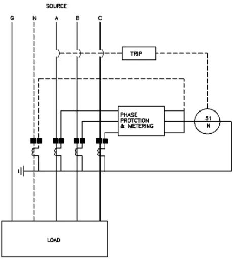
If a system has a solidly grounded neutral, the resulting ground-fault current magnitude will be relatively high, requiring a residual connected ground-fault relay. This relay, shown in Figure 3-3, monitors the outgoing ground-fault current.
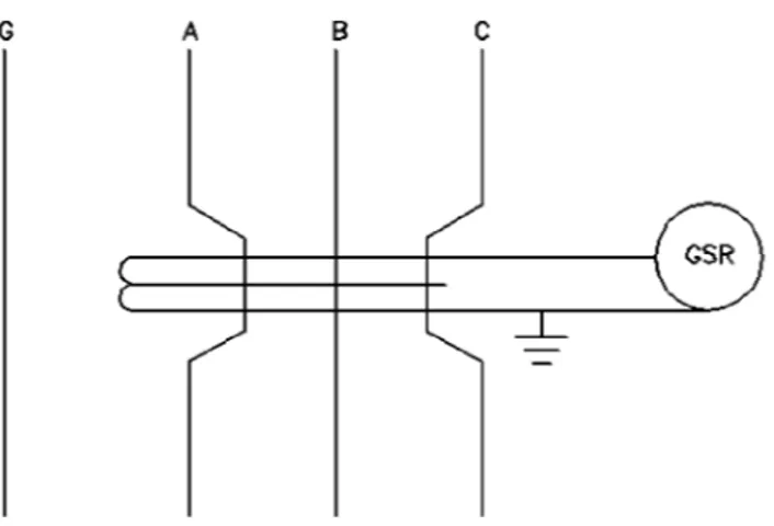
If the system has a resistance grounded neutral, the ground-fault current magnitude will be relatively low, 1200 A or less. To detect these currents, use a ground sensor with a secondary connected ground-fault relay as shown in Figure 3-4.
3.7.4 Low-voltage systems
As previously discussed, low-voltage systems for health care facilities are generally three-phase, four-wire systems. These systems usually contain effectively grounded normal power source neutrals. Here the alternate power source neutral may, or may not be, effectively grounded at the alternate source. The ground-fault schemes applicable will depend on how the alternate power supply is grounded.
For feeder circuits having no neutral conductor requirements (three-phase, three-wire loads), or for three-phase, four-wire loads where the neutral conductors are not electrically interconnected between power source on the load side of the feeder breaker, residually connected, ground-fault relay, or integral ground-fault relays (see Figure 3-6, Figure 3-7, and Figure 3-8) may be applicable for the feeder overcurrent device.
Figure 3-4—Ground-fault sensor and ground-fault relay
Figure 3-7—Ground sensor fault relay
For feeder circuits with neutral conductor requirements where the neutral conductors are electrically interconnected between power sources on the load side of the overcurrent device, “outgoing current method” schemes will be applicable. Figure 3-9 is an example of such a circuit.
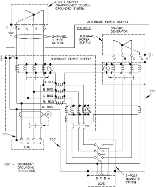
Typical ground-fault relaying systems are shown (see Figure 3-10 and Figure 3-11) for a health care facility power system that consists of normal and alternate power supplies. The power systems shown in Figure 3-10 have an electrical power conductor interconnection between power supplies. Note the vectorial summation of ground-fault currents (outgoing current method) in the relaying scheme required for the power system shown in Figure 3-10. In both Figure 3-10 and Figure 3-11, ground-fault relay R2 is optional.
Figure 3-10—Ground-fault scheme for a normal and alternate power supply having an electrical power conductor (neutral) interconnection
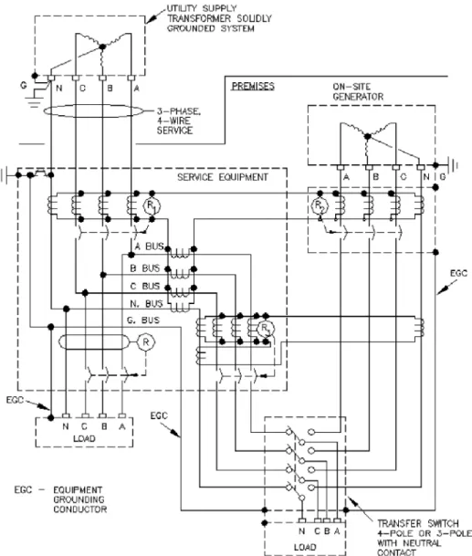
Figure 3-11—Ground-fault scheme for a normal and alternate power supply with no electrical power conductor interconnection
3.8 Electrical equipment selection, installation, and testing
3.8.1 Equipment selection
IEEE Std 141 (IEEE Red Book) and IEEE Std 241 (IEEE Gray Book) describe electrical power distribution equipment in detail. However, engineers must consider more criteria when using this equipment in health care facilities, including the following:
a) Reliability, protection, and coordination requirements b) How rapidly vital service can be replaced following an outage c) Initial cost including installation and cost of space
d) Maintenance facilities, maintenance cost, availability
e) Listing and labeling of equipment according to recognized standards by a nationally recognized testing laboratory (NRTL)
Remember that not just revenues or production will be lost should the system fail, but possibly human lives. The system should therefore provide the most reliable power possible (within economic feasibility) to patients and procedures that require electrical power. All the components used in the electrical system for health care facilities should provide a reliable and safe distribution system. Carefully consider the location of the electrical components during the design to minimize exposure to hazards such as lightning, storm, floods, earthquakes, fires, or toxic and/or environmental hazards created by adjoining structures or activities.
3.8.2 Working space
Provide ample working space around electrical components to allow and permit all tasks, installation, maintenance, testing, operating, etc., to be performed in a safe manner. See the NEC, NFPA 70B, and NFPA 70E.
3.8.3 Labeling
Ensure that installers properly label all distribution system components. Equipment such as switchgear, switchboards, motor control centers, panelboards, ATSs, etc., should all have engraved plastic nameplates (that designate source, purpose, and loads served) applied on incoming sections, tie sections, and feeder sections. All cables, busways, and buses should also be identified as to phase, to assist in maintaining proper phase sequence. Maintenance staff will be able to more effectively service the equipment it if follows a consistent method of labeling. Finally, the NEC requires arc flash labeling for equipment requiring maintenance or adjustment while energized.
3.8.4 Acceptance testing
electrical components can begin acceptance testing for the system. This testing should include all components including protective devices and circuitry, control circuitry, etc., to assure proper operation. Refer to NFPA 70B and the NETA Acceptance Testing Specifications (ATS).
3.8.5 Segregation of services
In selecting and installing the electrical distribution components for the essential electrical system, give high priority to achieving maximum continuity of the electrical supply to the load. To achieve this high reliability, the components (distribution circuitry, electrical equipment, etc.) for the essential electrical system should be installed so that they are physically separated from the non-essential power system components. Furthermore, as in NFPA 99, each branch of the emergency system should be installed physically separate and independent of the others and of all other wiring. The only exception to this rule would be when an electrical component such as a transfer switch requires two separate services.
3.8.6 Equipment selection
The following subclauses discuss the equipment commonly applied in health care facilities. Considerations mentioned here are those of specific concern in a health care facility. The in-depth considerations as outlined in IEEE Std 141 (IEEE Red Book) and IEEE Std 241 (IEEE Gray Book) should be understood to assist in choosing proper equipment.
3.8.7 Transformers
While transformer operating cost is an important factor when selecting a transformer, engineers should consider initial cost, operating costs of no-load and load losses, reliability, sound level, thermal life, overload capability, ability to supply nonlinear loads, installation costs, size, weight, availability of application, and servicing resources. Ideally, the no-load losses and load losses should be at a minimum at the normal loading point of the transformer [i.e., a transformer whose load losses are four times as large as the no-load losses would be most efficient at approximately 50% of its nameplate (base) rating]. 3.8.8 Switchgear, switchboards, and motor control centers
Locate electrical switchgear as close as possible to their loads to shorten cable runs, reduce losses in the cables, and minimize voltage drops. Do not locate these pieces of equipment near electronic monitoring equipment that is sensitive to electromagnetic interference (EMI). If this is unavoidable, consider shielding the electronic equipment or specifying the electronic equipment to be compatible with the EMI that may be present. Plan for adequate clearances and ventilation for present equipment and possible future expansions.
IEEE Std 739™ (IEEE Bronze Book™) and to ANSI C57.12.10 for additional recommendations regarding metering.
3.8.9 Protective devices
Carefully coordinate OCPDs to provide complete coordination of the system. The following four different kinds of circuit interrupting devices have two basic elements that provide a detecting function and a switching function.
a) Circuit breakers equipped with protective relays or direct acting trips b) Contactors equipped with overload relays
c) Transfer switches equipped with voltage and frequency sensing relays d) Switches equipped with fuses
When applied within their ratings, the switching devices are generally capable of performing the following:
1) Contactors and transfer switches. Repetitively closing, carrying and interrupting normal load currents; interrupting overload currents; withstanding but not interrupting any abnormal currents resulting from short circuits (unless circuit breakers or fuses are built-in).
2) Switches. Closing; carrying and interrupting load current; and when properly coordinated with a fuse, withstanding but not interrupting any abnormal current resulting from overloads and short circuits. The fuse provides detection and inter-ruption feature for overloads and short circuits within its design characteristics.
NOTE—When switches include “shunt trip coils” they can be electrically tripped by ground-fault relaying equipment, or other controls.3
3) Closing; carrying and interrupting load current; withstanding and interrupting overload, short circuit, and ground-fault currents.
Of these devices, only circuit breakers and fused switches can be OCPDs that interrupt overload, short-circuit currents, and arcing ground-fault currents. Transfer switches transfer loads from one source of power to another by monitoring power source voltage. Contactors are applied as load powering devices such as motor starters, lighting, etc.
Protective devices use three types of detectors—fuses, relays, and direct acting trips. — Low-voltage fuses detect and interrupt the abnormal current in one nonadjustable
element. They are thermal-type devices and are sensitive to ambient temperature and the current flowing through them. The continuous current ratings typically are based in open air, and when applied inside equipment, mayneed to be derated to account for increased ambient temperature. Normally, an 80% derating factor is applied. Fuses are single-phase devices and must be installed in each phase of a three-phase circuit fusible switch. The application of fuses as OCPDs is similar to applying circuit breakers.
3Notes in text, tables, and figures are given for information only and do not contain requirements needed to
High-voltage fuses operate in a similar manner except that they are more often practical for interrupting short circuits. Also, their fuse size (e.g., 25E) does not directly relate to the current at which they operate.
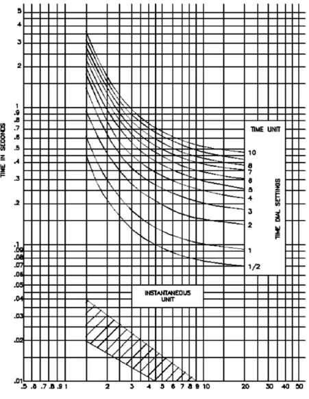
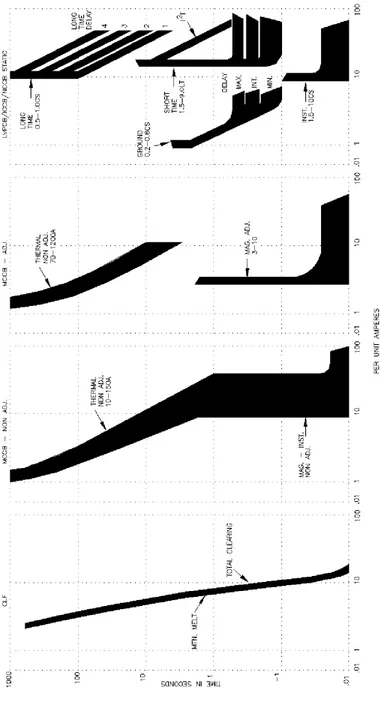
— Protective relays respond to electrical quantities that change during normal and abnormal conditions. The basic quantities that may change are the magnitude and/ or direction of current, voltage, power, phase angle, and frequency. Protective relays are responsive to one or more of these quantities instantaneously or at a time rate dependent on magnitude. Figure 3-12 shows a typical relay response curve. Generally, these relays are field adjustable, have a wide operating ambient temperature range, and have a drawout construction. They may include special features such as sensitivity to directional quantities only, etc. Relays, although not limited to, are normally applied in conjunction with high- and medium-voltage circuit breakers. Upon pickup, at the selected current setting, and after any time delay selected, the relay trip contacts close toenergize the trip circuit of the circuit breaker, which releases the stored energy (spring) holding mechanism that then opens all circuit breaker poles. Electronic (solid-state) and microprocessor based tripping units for low-voltage circuit breakers operate similarly to other protective relays except the circuit breaker tripping devices are often integral with the removable circuit breaker element. Figure 3-13 shows several typical, lower volt-age response curves.
— Direct acting trips respond to current either instantaneously or at a time rate dependent on the current magnitude. They are mounted inside low-voltage circuit breakers in series with the breaker trip mechanism, which opens all circuit breaker poles. They are of a thermal-magnetic, magnetic, or electronic design. As for fuses, the thermal type requires a derating factor consideration. Some units are ambient compensated. The electromagnetic, electromechanical, or electronic (static) types are generally field adjustable.
Trip units generally do not respond to load or circuit conditions that generate minor harmonic distortions. Where a trip unit will experience high harmonic content, or where the loads are pulsating, the engineer should work with the manufacturer of the device to ensure proper operation of the device. Nuisance trip signals from electronic trip units may result when the trip unit has a memory circuit. (See 3.7.2 for more information on memory circuits.)
Medium-voltage systems generally accomplish ground-fault detection by electromagnetic overcurrent relays and toroidal or bar-type current transformers (CTs). In low-voltage systems, microprocessor relays and matching current sensors, whether integral or external to the protective device, provide the ground-fault protection.
Note that ground-fault detection requires additional attention as outlined in 3.7.1.4 if nuisance power outage is to be avoided.
3.8.10 Transfer switches—Automatic and manual
Transfer switches transfer from one power source to another to maintain service to the essential power system and designated equipment. Due to their important function in the health care facility power system, they must be listed for emergency electrical service and have adequate capacity for the loads being served. In addition, locate them to provide reliable service to downstream loads. Generally, the switches should be located as close to the loads to be served as possible (thus implying more, smaller switches, rather than fewer, larger switches). Furthermore, they must have adequate withstand ratings to prevent contact welding due to load, overload, or short-circuit currents.
Automatic transfer switches (ATSs) operate electrically and latch mechanically to prevent change of state, open or closed, whenever control power is unavailable.
An ATS permits the transfer and retransfer of the load automatically when required. Manual or nonautomatic transfer switches also have a mechanical latching feature. For related requirements such as switch position indication, interlocking, voltage sensing, time delay, etc., refer to NFPA 99, the NEC, NFPA 110, and NFPA 111.
To permit ease of maintenance, consider incorporating bypass/isolation features into these switches. This feature will allow normal preventive maintenance and breakdown maintenance to be performed when required with minimal, or no, disruption to patient services.
3.8.11 Generators
See Chapter 5.
3.8.12 Special wire, cable, and busway
In addition to meeting the general code requirements as noted in the NEC (Chapter 1 through Chapter 4), certain hospital/health care occupancies require special attention (i.e., wire and cable installed in areas classified as hazardous must meet certain installation requirements of Class 1, Division 1). One such hazardous area would include any remaining areas where staff will use flammable anesthetizing agents. These areas must have wire and cable installed in approved rigid metal raceways utilizing threaded connections that are properly sealed. All boxes, fittings, and joints must be suitable for hazardous locations.
Wiring downstream of the isolation transformers cannot have voltages higher than 600 V between conductors. The conductors shall have a dielectric constant of 3.5 or less and be color coded as in the NEC (Article 517). Installers of this these conductors must do it carefully so as to not increase the conductors’ dielectric constant.
3.8.13 Panelboards
between the panelboard and load. This close placement reduces voltage drops on the circuits. Locating panels in electrical equipment rooms will allow future maintenance and revisions to these to be done much more safely than if they are located in corridor walls. Including bus bars and spare circuits will allow for much more economical future additions of new circuits.
Good design and code requirements include a low-resistance ground path from all panelboard ground buses back to the source of power. This ground path will limit shock hazards and provide a low-impedance path for ground-fault currents in a grounded system.
3.8.14 Isolated power supplies
Isolated power supplies consist of an isolating transformer, motor-generator sets or batteries, a line isolation monitor (LIM), and the ungrounded circuit conductors and overcurrent protectors. Refer to Chapter 4 for more on this topic.
3.9 System arrangements
In designing the electrical power system, carefully consider how to select the proper electrical system arrangement to provide a reliable power system. A power service consisting of two or more separate dedicated utility service feeders, fed from separate substations or from separate distribution buses, provide a much higher degree of reliability than one utility service feeder, but often require additional initial and ongoing fees from the utility company. Furthermore, the reliability is enhanced even more if each service feeder is installed separately (i.e., on separate pole lines) so that a fault in one feeder circuit will not affect the other feeder.
Distribution system arrangements should be designed and installed to minimize interruptions to the electrical systems due to internal failures. Among the factors to be considered as outlined in NFPA 99 are
a) Abnormal current-sensing devices, both phase current and ground current, should be selected and set to quickly disconnect any portion of the system that is overloaded or faulted.
b) Abnormal voltage conditions such as single-phasing of three-phase utilization equipment, switching and/or lightning surges, voltage reductions, etc., should be anticipated.
c) Capability to quickly restore any given circuit after clearing a fault or overload. d) Ability of system to be modified for accepting increasing loads in the facility and/
or changes in supply capacity.
e) Stability and power capability of the alternate power systems’ prime mover during and after abnormal conditions.