Visual DaVinci Extension for Real Robot Control
Champredonde Raúl1 Romero, Fernando2 De Giusti Armando3
Laboratorio de Investigación y Desarrollo en Informática4 Departamento de Informática
Facultad de Ciencias Exactas Universidad Nacional de La Plata
Abstract
Visual DaVinci is a visual programming language whose purpose is programming learning.
The development environment allows the implementation, execution and debugging of the algorithms specified with the mentioned language.
The implementation of an algorithm may be carried out in a conventional way, that is, by writing each of its instructions, or by means of a visual diagram, which can in turn be used as a designing tool.
Both implementations may be indistinctly used at any moment of the development of a program.
An extension that allows to control a real robot with moving capacity and which is able to execute the algorithms implemented in Visual DaVinci, is described in this paper.
Keywords
Visual Programming Language. Programming Learning. Robot.
1
Part-Time Practical Lessons Coordinator. Iniciation Grant at the CONICET. LIDI, Department of Computer Sciences, Faculty of Exact Sciences, UNLP. E-mail: [email protected]
2
Part-Time Practical Lessons Coordinator. LIDI, Department of Computer Sciences, Faculty of Exact Sciences, UNLP.
E-mail: [email protected] 3
Full-Time Chair Professor. Principal Researcher at the CONICET. Director of the LIDI, Department of Computer Sciences, Faculty of Exact Sciences, UNLP.
E-mail: [email protected] 4
Introduction
This work is part of a research and development line which started some ten years ago and whose main purpose is to assist the teaching of the first concepts of computers programming taught at the entrance course to the higher courses of studies Licenciature on Computer Sciences and Computer Analyst at the Faculty of Exact Sciences of the National University of La Plata, and at the subject Computers Programming of the same courses of studies.
One of the most recent developments in this regard is a visual programming language [BURN, 1994] [CHAN, 1990] [GLIN, 1990a] [GLIN, 1990b] called Visual DaVinci [CHAM, 1997], which is used as a response to technological revolution as regards development tools and programming paradigms.
Visual DaVinci’s visual environment allows the student to develop and test algorithms, and at the same time encourages a good programming style by integrating a development and trial environment and by encouraging the use of design and implementation tools and techniques.
One of the extensions made to Visual DaVinci, which consists of the incorporation of a real robot with movement, rotation and perception capacity and which executes instructions of algorithms developed in Visual DaVinci, is presented in this article. [LEWI, 1993].
Visual DaVinci
The environment runs under Windows using the same interface characteristics as most applications running under Windows. This helps students to get familiar with a graphic environment similar to the one they will have to use during their professional careers; however, for the time being, they do not need to know the specific details of this type of environments or operating systems.
The general aspects of the development environment (Figure 1) are similar to the general aspects of those products known as “visual”. In particular, it shares its main characteristics with Borland Delphi [CALV, 1995].
It consists of a main window with its menu and general buttons bar, a code edition window, a visual diagram edition window, and a window showing the city through which the robot moves, and where its itinerary can be seen during the execution of an algorithm.
The purpose of the main window is to assist the global handling of program files, printing, selection of different visualization options and environment configuration, on-line help, and so on. It also provides syntax verification, execution and depuration options.
The diagram editor is used to specify a program in a visual way.
Most of the visual diagrams editor window is devoted to the diagram itself, which may contain several pages. The first of these pages includes a specification of the main program, and the other pages include one process each.
The part for the definition of the formal parameters of the first page cannot be used, since the main program does not receive or return parameters.
The upper part of the window presents a button bar, each of which is associated to a program element.
The insertion of the different elements inside the diagram is done by pressing the corresponding button and by clicking the mouse where that element is to be placed.
Buttons are divided, according to the type of element which is associated to them, into the following groups: general use, variables declarations, processes and formal parameters, primitive instructions, simple and compound sentences, control structures, invocation to system processes, system variables utilization, mathematical and logical operators, and numerical and logical values.
For the following three situations, instead of pressing a button from the upper bar and clicking inside the diagram, the technique known as drag&drop is used:
• To change the position of a visual element corresponding to a body sentence. • To place a variable, an output parameter, or an input/output parameter to the left of
an application.
• To place a variable, an input parameter, or an input/output parameter as part of an expression.
Every visual element added to the diagram, modified or deleted, is automatically translated to textual code. This translation is instantly shown in the corresponding code editor position, using the language syntax specified in the annex.
The code edition window is a very simple text editor, which provides some facilities such as semiautomatic indentation; cutting, deleting or copying the selected code; and searching or replacing the code.
The city window contains the image of a set of blocks delimited by the hundred streets and hundred avenues. During the execution of an algorithm, the robot can be seen circulating through the city and leaving a red line wherever it goes, as well as flowers, papers and obstacles.
Since the whole city is larger than the window, scrolling bars can be used so that the user can see any part of the city. If during the execution of a program the robot goes to one of the unseen sections of the city, an automatic relocation of the window will take place, so that the user is continuously following the trajectory of the robot.
On the system variables inspector, the current values of the system variables related to the robot during the execution of a program are shown. These values correspond to the current robot coordinates, that is, the avenue and the street where it is located, its direction, and the number of flowers and papers in the corresponding bags.
The environment provides certain options which can be modified by the user.
These options automatically show the number of flowers, papers and obstacles that will appear on the way, as well as the areas where they will appear. They also indicate if the obstacles are simple or are forming a barrier.
It is also possible to highlight the currently running code line and to establish a delay between the execution of two instructions.
Micromouse Robot Kit
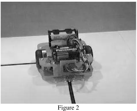
The robot used for this work (Figure 2) [LYNX, 1998] travels on a horizontal surface. It consists of a pair of independent wheels, each impelled by a servomechanism modified to act as a motor, and mounted on a plastic chassis built for that purpose. On this chassis there are also three different sensors:
• Tracker line tracking: It follows a line on the floor.
• Infrared proximity detector: It detects the obstacles to the right, to the left, or at the center.
• Collision switch: It detects collisions to the left or to the right. The pair of wheels allows the following movements:
• Straight forward. • Straight backwards. • Rotation to the right. • Rotation to the left.
The “Tracker line tracking” is a device which senses a track consisting of a different color line. It consists of 3 diode and infrared detector pairs, and of an integrated circuit with 6 inverters with smith-trigger input.
Each diode-detector pair is aligned in such a way that if it passes through a place reflecting the light emitted by the led, the detector is activated. On the other hand, if the surface does not reflect the light, the detector is not activated. Therefore, when the three pairs are placed perpendicularly to a reflecting paint track, when the robot comes near the border of the track, one of the detectors will be deactivated. This will allow, knowing that the deactivated detector is the one to the left or the one to the right, to correct the direction of the robot, thus keeping it centered on the track as if it were a rail.
The integrated circuit, with its high input impedance and its hysteresis (Shmith-trigger input), allows a high noise immunity in the device output. These signals are transmitted in parallel to the microcontroller board, which transmits them serially to the PC.
The infrared proximity detector consists of two infrared diodes, one to the front right and the other to the front left, which are alternately enabled and disabled, and an infrared sensor. When there is an obstacle reflecting the emission of infrared rays towards the sensor, depending on which LED is enabled at the moment, it can be determined if the obstacle is located to the right, to the left or in the center (if the obstacle is detected when both sensors are activated).
There are two collision switches, which are located at the front of the robot. They are activated if a collision takes place. Depending on which of the two switches is activated, the side of the collision is determined. This sensor is unnecessary if there is a proximity detector.
The servomechanism is a device consisting of a motor, a reducing box, and a potentiometer which allows to re-feed the position of the shaft of the reducing box.
Due to the mechanical design of the potentiometer, it cannot be rotated more than 180 degrees between the ends. If the potentiometer is withdrawn from the servo, by eliminating the mechanical top and adding a fix reference tension, it is transformed into a continuous rotating motor.
[image:5.612.187.425.43.235.2]Rotation speeds and their directions are obtained by providing the motor with pulses of variable width: thus, with a pulse of 1ms, it rotates to the left, with a pulse of 1.5ms it stops, and with a pulse of 2ms it rotates to the right. Tensions are provided by a Paralax PICSC8 microcontroller.
This microcontroller can communicate through an RS-232 interface, which allows to connect the robot to a PC from which the commands to both act on the servos and read the status of the robot sensors are sent.
Implementation aspects
The implementation of this environment was carried out with Delphi.
The chosen development tool was Delphi because it allows to create the application interface very easily, its programming language is object-oriented (Object Pascal), it is efficient enough as regards compilation times – as is the executable it generates -, and it has the same multimedial and data base management capabilities as other similar tools.
These characteristics are very important for the development of friendly and flexible systems.
The type of interface had to be carefully considered, since final users would be students getting familiar with computers and for whom, in most of the cases, this would be their first experience using a development environment. Therefore it was indispensable that the system could be easily and intuitively used.
Syntax verification, as well as a complete or step-by-step execution, requires a rather complex treatment, with the participation of several dynamic structures and interactions between different system components. The use of object-oriented programming is particularly suitable in this case, without even considering the advantages of this kind of programming when developing almost any application.
Clarity and code legibility were prioritized over code efficiency for the implementation in order to facilitate the adaptation process required by the planned extensions.
Algorithms syntax verification and their execution are the most important aspects of the implementation.
For algorithms syntax verification, objects dynamic structures are built. Each object knows the way in which it should be analyzed. For this purpose objects such as TSentence, TPrimitive, TAssignement, TInvocation, TSequence, TIf, TWhile, TRepeat, TExpression, TProgram, TSubprogram, TVariable, TParameter, etc. were defined.
Once the correction of the algorithm is secured, the dynamic structure of objects built during the syntax verification stage is also used for the execution of the algorithm. This is why each of the objects representing the different elements of an algorithm has a method which allows its execution.
The use of objects for the development of this system has considerably relieved its implementation. Each of the hierarchy objects is provided with the capacities needed to carry out its own syntax verification and its own execution. If inheritance and polymorphism benefits are added to these capacities, a considerable reduction of the system complexity and of the number of necessary code lines is obtained.
Thanks to a suitable initial design, the extension allowing Visual DaVinci to handle a real robot only affected a small portion of the program executor.
Future Works
The real robot does not currently count with a way of recognizing flowers and papers (or their real representation) in the city. This is why this recognition is still done by means of the information provided by the city window of the development environment.
Two new extensions are being considered. One of them is the assembly of a camera on the robot currently used to allow a remote detection of obstacles and colors identification.
The other extension planned is the incorporation of an arm to collect the different elements. This arm is already being used for other works, the idea here would be to mount it on the mobile robot.
Conclusions
An extension to Visual DaVinci which allows to handle a real robot for the execution of algorithms developed by students of the Entrance Course and first year subject Computers Programming, to apply the concepts there taught, has been presented
Bibliography
[BURN,1994] "Visual Object-Oriented Programming". M. M. Burnett, A. Goldberg, T. G. Lewis. Prentice Hall and Manning. 1994.
[CALV, 1995] Calvert C., Delphi Unleashed, Sams Publishing, 1995.
[CHAM, 1997] Champredonde R., De Giusti A., Herramienta Visual para la Enseñanza de Programación Estructurada, III Congreso Argentino de Ciencias de la Computación, 1997, La Plata. 1997.
[CHAN, 1990] "Visual Languages and Visual Programming". S.-K. Chang. Plenum Press. 1990.
[CHAR, 1996] Charte F., Programación Avanzada con Delphi 2.0, 1996.
[GLIN, 1990a] "Visual Programming Environment: Paradigms and Systems". E. P. Glinert. IEEE Computer Society Press. 1990.
[GLIN, 1990b] "Visual Programming Environment: Applications and Issues". E. P. Glinert. IEEE Computer Society Press. 1990.
[GOLI, 1990] "A Method for the Specification and Parsing of Visual Languages". E. J. Golin. Brown University. 1990.
[HUNT, 1985] "Compilers. Their Design and Construction Using Pascal". R.Hunter. John Wiley & Sons. 1985.
[LEWI, 1993] "Control of Robot Manipulators". Lewis, Abdallah, Dawson. MacMillan, Maxwell. 1993.
Annex: Language Syntax
<Program>::=
<Program heading> [<Declarations>] <Body>
<Program heading>::=
programa <Program ID>
<Program ID> ::= <Identificator>
<Identificator>::=
(A|B|C|D|E|F|G|H|I|J|K|L|M|N|O|P|Q|R|S|T|U|V|W|X|Y|Z|a |b|c|d|e|f|g|h|i|j|k|l|m|n|o|p|q|r|s|t|u|v|w|x|y|z){A| B|C|D|E|F|G|H|I|J|K|L|M|N|O|P|Q|R|S|T|U|V|W|X|Y|Z|a|b| c|d|e|f|g|h|i|j|k|l|m|n|o|p|q|r|s|t|u|v|w|x|y|z}
<Declarations>::=
[<Processes declaration>] [<Variables declaration>]
<Processes declaration>::= procesos
__{<Declaration of a process>}
<Declaration of a process>::= <Process heading>
[<Declarations>] <Body>
<Process heading>::=
proceso <Process ID>[(<Formal parameters>)]
<Process ID>::=
<Identificator>
<Formal parameters>::=
{<Formal parameter>, }<Formal parameter>
<Formal parameter>::=
<Input formal param.>| <Output formal param.>| <I/O Formal param.>
<Input formal param.>::=
E <Input formal param. ID>: <Type>
<Input formal param. ID> ::= <Identificator>
<Output formal param.>::=
<Output formal param. ID> ::= <Identificator>
<I/O formal param.> ::=
ES <I/O formal param. ID>: <Type>
<I/O formal param. ID> ::= <Identificator>
<Type>::=
numero|boolean
<Variables declaration>::= variables
__<Declaration of a variable>
__{<Declaration of a variable>}
<Declaration of a variable> <Variable ID>: <Type>
<Variable ID>::= <Identificator>
<Body>::= comenzar
__{<Sentence sequence>} fin
<Sentence sequence>::= <Sentence>
{<Sentence>}
<Sentence>::=
<Primitive>|<Simple sentence>|<Compund sentence>
<Primitive>::=
iniciar|mover|derecha|tomarFlor|tomarPapel|
depositarFlor|depositarPapel
<Simple sentence>::=
<Assignment>|<Invocation>
<Assignment>::=
(<Variable ID>|
<Output formal param. ID>|
<I/O formal param ID>) := <Expression>
<Expression>::=
{(<Value>|<Variable ID>| <System var. ID>|
<Input formal param. ID>| <I/O formal param ID>|
(<Expression>)|-<Expression>|
~<Expression>) <Operator>} (<Value>|<Variable ID>| <System var. ID>| <Input formal param. ID>|
(<Expression>)|-<Expression>|~<Expression>)
<Value>::=
<Numeric Value>|<Boolean value>
<Numeric value>::=
0|1|2|3|4|5|6|7|8|9{0|1|2|3|4|5|6|7|8|9} [.0|1|2|3|4|5|6|7|8|9{0|1|2|3|4|5|6|7|8|9}]
<Boolean value>::= V|F
<System var. ID>::=
PosAv|PosCa|HayFlorEnLaEsquina|
HayFlorEnLaBolsa|HayPapelEnLaEsquina|
HayPapelEnLaBolsa
<Operator>::=
<Arithmetic operator>|<Boolean operator>| <Relational operator>
<Arithmetic operator>::= +|-|*|/
<Boolean operator>::= ~|&||
<Relational operator>::= =|<>|<|>|<=|>=
<Invocation>::=
(<Process ID>|<System process ID>) [<Real parameters>]
<System process ID>::=
Pos|Informar
<real parameters>::=
<Input real param.>|<Output real param.>| <I/O real param.>
<Input real param.>::= <Expression>
<Output real param.> ::= <Variable ID>|
<Output formal param. ID>| <I/O formal param. ID>
<I/O real param.> ::= <Variable ID>|
<I/O formal param. ID>
<Compound sentence>::=
<Selection>|<Conditional iteration>| <Unconditional iteration>
<Selection>::=
__<Sentence sequence> [sino
__<Sentence sequence>]
<Conditional iteration>::= mientras <Expression> __<Sentence sequence>]