Evolutionary Algorithm for State Encoding
Valery Sklyarov, Iouliia Skliarova University of Aveiro, Department of Electronics and Telecommunications/IEETA, 3810-193 Aveiro, Portugal
[email protected], [email protected] WWW home page: http://www.ieeta.pt/~skl/
http://www.ieeta.pt/~iouliia/
Abstract. This paper presents an encoding technique that is common for many different logic synthesis problems. It enables us to construct a system of Boolean functions, and then to decompose this system into sub-systems in such a way that a dependency of functions, included into each sub-system, on the respective arguments is reduced. For complex applications such type of encoding has a high computational complexity and the paper proposes a novel evolutionary algorithm for the solution of this problem.
1 Introduction
There are many combinatorial tasks that involve encoding algorithms. These tasks appear in particular at various steps in the logic synthesis of digital circuits. One of these tasks is based on such encoding technique that enables us to construct a system of Boolean functions, and then to decompose this system into sub-systems for which we are able to reduce dependency of the functions, included into each sub-system, on the respective arguments [1,2]. Commonly the logic scheme of a finite state machine (FSM) is composed of a combinational circuit and a memory (a set of flip-flops). The combinational circuit implements a system of Boolean functions D1,...,DR that
depend on variables x1,...,xL,τ1,...,τR. The x1,...,xL are external input variables and
τ1,...,τR bring the code of the state afrom from which we have to carry out transition(s).
The functions D1,...,DR enable the FSM to calculate the code of the next state ato. The
lines τ1,...,τR are the outputs from the FSM memory and the lines D1,...,DR are the
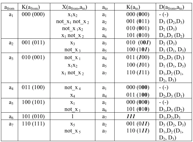
inputs to the FSM memory. For example, the FSM can be described as shown in Table 1 (at the beginning let us ignore all symbols enclosed in parenthesis). Here, afrom - is an initial state, K(afrom) and K(ato) - are the codes of the states afrom and ato,
respectively, ato - is the next state, X(afrom,ato) - is a product of inputs that forces a
conditional transitions (i.e. for all transitions except from the state a6), all the
sub-functions of D1,...,D3 that must be activated on transitions from a state, depend on
both the state and inputs. We will say that a sub-function is active if it has to be assigned to 1. Since all the sub-functions depend on states and inputs, the relevant Boolean expressions, that are used to calculate the values D1,...,D3, contain variables
from the full set {x1,...,xL,τ1,...,τR}, where L - is the number of external inputs (in our
[image:2.612.146.476.186.430.2]example L=5) and R - is the size of the FSM memory (in our example R=3).
Table 1. An example of FSM
afrom K(afrom) X(afrom,ato) ato K(ato) D(afrom,ato)
a1 000 (000) x1x2
not_x1 not_x 2
not_x 1x2
x1 not_x 2
a1
a2
a3
a6
000 (000) 001 (011) 010 (001) 101 (010)
- (-) D3 (D2,D3)
D2 (D3)
D1,D3 (D2)
a2 001 (011) x3
not_x 3
a3
a5
010 (001) 100 (101)
D2 (D3)
D1 (D1, D3)
a3 010 (001) not_x 1
x1x2
x1 not_x 2
a4
a5
a7
011 (100) 100 (101) 110 (111)
D2,D3 (D1)
D1 (D1, D3)
D1,D2 (D1,
D2, D3)
a4 011 (100) not_x 4
x4
a1
a4
000 (000) 011 (100)
- (-) D2,D3 (D1)
a5 100 (101) x1
not_x 1
a1
a6
000 (000) 101 (010)
- (-) D1,D3 (D2)
a6 101 (010) 1 a7 111 D1,D2,D3
a7 110 (111) x5
not_x 5
a2
a7
001 (011) 110 (111)
D3 (D2, D3)
D1,D2 (D1,
D2, D3)
Consider all sub-functions of D1,...,D3 that are generated for proper transitions
from a state. For example, sub-functions D13,...,D33, that have to be activated in
transitions from the state a3 (later we will also mark such sub-functions with a
corresponding superscript) are the following: D13 = a3x1; D23 = a3 (not_x1∨ not_x2);
D33 = a3not_x1 (these expressions can easily be obtained from Table 1). Note that
since there exist 3 transitions from a3, they can be distinguished with the aid of just
two Boolean variables, such as D13,...,D33. As a result, inputs such as x1 and x2 can
affect (and change) just two variables from the set {D13,...,D33} and the remaining
variables (in our example one variable from the set {D13,...,D33}) can be independent
of external inputs from the set X = {x1,...,xL}, i.e. they will only depend on the
current state (in our example on the state a3). If the number of different (non
coinciding) next states in state transitions from am is equal to qm, then (R-intlog2qm)
variables from the subset D1m,...,DRm can be independent of the input variables from
the set X.
the number of FSM states and for our example M=7) that do not depend on input variables, are marked with bold and italic bold fonts. Note that the bold font has been used for passive values, and italic bold font for active values of the sub-functions.
Now the combinational circuit S of the FSM can be decomposed into two sub-circuits in such a way that the first sub-circuit Sax implements all active values of
D11,...,D3M that are not bold. The functions of Sax depend on both FSM inputs and
states. The second sub-circuit Sa implements all active values of D11,...,D3M that are
bold. The functions of Sa depend only on the states and for our example they are:
D1 = a3∨ a6; D2 = a6∨ a7; D3 = a2∨ a6∨ a7;
Such functions are well suited for minimization and are usually very simple. For instance, Sa can be constructed from just four 2-input logic elements of types XOR,
AND and OR, which convert values of τ1,τ2,τ3 to values of D1,D2,D3. On the other
hand, such kind of decomposition enables us to essentially simplify the sub-functions of Sax, i.e. the active sub-functions that are not bold in Table 1. Finally, even for our
very simple example, the proposed state encoding permits the number of logic elements to be reduced by approximately 20%.
Similar problems appear in a large number of practical applications and we will point out just some of them:
• One-level control circuits based on blocks, such as programmable logic arrays (see [3, p. 182]. It allows reducing essentially the total number of interconnections by eliminating the repeated outputs for different blocks; • RAM-based implementation of FSMs [2], etc.
The paper presents an evolutionary algorithm that allows the encoding considered above to be achieved. It should be noted that the technique of artificial evolution has been widely used for hardware design [4]. Evolutionary algorithms (EA) are based on a process of "generate-and-test" [5] and this strategy can be applied at different levels. For example, in [6] a genetic algorithm is employed to search for circuits that represent the desired state transition function. Many examples demonstrating EAs that have been successfully employed for hardware design are presented in [7-9]. For some circuits they produced unforeseen results of very high quality (for example, [10]), which have never been obtained by human designers.
The remainder of this paper is organized in four sections. Section 2 presents the detailed description of the proposed evolutionary algorithm. Section 3 discusses feasible variations of the algorithm. Section 4 presents the results of experiments, which clearly demonstrate the advantages of the proposed encoding technique. The conclusion is in section 5.
2 Evolutionary
Algorithm
The basic idea of EA was used for the considered problem in the traditional simple way [11]. The algorithm includes the following steps:
1. Production of an initial population composed of individuals that represent a set of randomly generated codes for a given number of variables (FSM states).
3. Variation of the population by applying such operations as reproduction, mutation and crossover. A reproduction operator makes a copy of the individual (with a probability based on its fitness) for inclusion in the next generation of the population. A mutation operator creates new individuals by performing some changes in a single individual, while the crossover operator creates new individuals (offspring) by combining parts of two or more other individuals (parents) [9].
4. Performing a selection process, where the most fit individuals survive and form the next generation.
Points 2-4 are repeated until a predefined termination condition is satisfied. Let us assume that a population π including ν individuals π1,...,πν has been
randomly generated. In order to evaluate each individual πι, ι=1,…,ν, it is necessary
to specify a fitness function. For our problem it is very easy. Let A={a1,...,aM} be a
set of variables that have to be encoded, M is the number of variables in the set A. The variables in each individual subset A(afrom) (where A(afrom) is a set of states to
which there exist direct conditional transitions from the state afrom, km=|A(afrom)|>1,
m=1,...,M) have to be encoded in such a way that the number wm (wm=R-intlog2km)
of their bits with the same indices have equal values. Here R=intlog2M is the
minimum number of bits in the codes of states assuming binary encoding. Thus, any solution for which the fitness function W is equal to Σwm (km>1, m=1,...,M) gives an
optimal result (we assume that such result exists, which, in fact, is not true for a general case). Actually we can discover several optimal results and for each of them the function W has the same maximum possible value. Any of these results provides the best solution to the problem so we just have to find out the first of them.
Now the fitness can be estimated very easily. For randomly generated codes πι
we have to calculate the function Wi and compare the result with the value W. The
less the difference W-Wi the better the fitness for the individual πι.
The next step produces a variation of the population and can be carried out by applying such operations as reproduction, mutation and crossover. Two kinds of reproduction have been examined and compared. The first one is based on elitist rule [11] where the best solutions in the population are certain to survive to the next generation. This rule has been implemented as follows. For reproduction purposes 10% of individuals with the best fitness have been copied to the next generation of the population. The second kind of reproduction uses the same percentage of individuals, but it is based on proportional selection [11].
The mutation operation runs on one parental individual selected with a probability based on fitness and creates one new offspring individual to be inserted into the new population at the next generation. In order to choose which parents will produce offspring, a fitness proportional selection is employed. Each parent πi is
assigned a weight Wi, calculated at the previous step. The probability of selection for
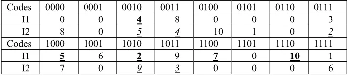
each parent is proportional to its weight. The main idea of the mutation operation will be illustrated by an example of state encoding for FSM with specification presented in [12]. The FSM has 10 states and the following transitions afrom⇒A(afrom): a1⇒{a2,a3,a4}, a2⇒{a2,a4,a5}, a3⇒{a6,a7,a8,a9}, a4⇒{a5}, a5⇒{a3},
a6⇒{a5,a7}, a7⇒{a3,a9}, a8⇒{a2,a10}, a9⇒{a10}, a10⇒{a1}. Since M=10 and R=4 for
Table 2. An individual I that has been selected for mutation operation
Codes 0000 0001 0010 0011 0100 0101 0110 0111
I 0 0 4 8 0 0 0 3
Codes 1000 1001 1010 1011 1100 1101 1110 1111
I 5 6 2 9 7 0 10 1
For the individual I all the state codes have to be examined and all the weights wI1,...,wIM that exceed the value 1 have to be calculated. Some (or all for the best
result) of these weights correspond to an optimal result. For all weights wIm that have
an optimal value the respective states am have to be selected (see in Table 2 bold
underlined numbers m of states am). For example, we have the following state
transitions a1→ {K(a2)=1010, K(a3)=0111, K(a4)=0010}, a2→{K(a2)=1010,
K(a4)=0010, K(a5)=1000}opt, a3→{K(a6)=1001, K(a7)=1100, K(a8)=0011,
K(a9)=1011}, a6→{K(a5)=1000, K(a7)=1100}opt, etc. Optimal solutions are indicated
by subscript "opt" and the respective bits (i.e. bits with coincident indices that have equal values) of the codes are marked with bold font. The mutation operation permits a new child individual to be created and includes the following steps.
Step 1. All the elements that correspond to an optimal solution (see bold
underlined numbers in Table 2) are included in the new individual (offspring).
Step 2. The codes for the remaining elements will be randomly regenerated in
such a way that just free codes (i.e. such codes that have not been already chosen at step 1) can be selected.
Crossover is the most complicated operation of the considered EA. The main idea of this operation will also be illustrated by the same example of FSM. Suppose that at some step of EA we have found the codes for two individuals I1 and I2 shown in Table 3 and these individuals were chosen to be parents for creating a new individual that is a child. For all weights wI1m(wI2s) that have an optimal value the
respective states am (as) have to be selected (see bold underlined numbers m of states
am for the first individual I1 and italic underlined numbers s of states as for the
second individual I2). The parents are chosen on the base of proportional selection [11].
Table 3. The results of encoding for two individuals
Codes 0000 0001 0010 0011 0100 0101 0110 0111
I1 0 0 4 8 0 0 0 3
I2 8 0 5 4 10 1 0 2
Codes 1000 1001 1010 1011 1100 1101 1110 1111
I1 5 6 2 9 7 0 10 1
I2 7 0 9 3 0 0 0 6
The crossover operation permits a new child individual to be created and includes the following steps.
Step 1. The first solution (see Table 4) is formed from the selected elements of
Step 2. Permitted selected elements from the second individual I2 (see italic
underlined numbers in Table 3) are added to the first solution (i.e. to the child). An element is allowed for step 2 if:
a) It was not included into the child during the first step; and
b) It does not have a code that has already been used during the first step. Table 5 shows the result of step 2 for our example.
Step 3. All the remaining permitted elements from the first and the second
individuals are added to the child. An element is allowed for step 3 if it has not yet been included in the child and:
a) It has the same code for both individuals I1 and I2; or
b) It is included in the second individual I2 and the respective code of the first individual I1 was not used for the states; or
c) It is included in the first individual I1 and the respective code of the second individual I2 was not used for the states;
Table 6 shows the result of step 3 for our example.
Table 4. The result of step 1
Codes 0000 0001 0010 0011 0100 0101 0110 0111
Child 4
Codes 1000 1001 1010 1011 1100 1101 1110 1111
Child 5 2 7 10
Table 5. The result of step 2
Codes 0000 0001 0010 0011 0100 0101 0110 0111
Child 4
Codes 1000 1001 1010 1011 1100 1101 1110 1111
Child 5 2 3 7 10
Table 6. The result of step 3
Codes 0000 0001 0010 0011 0100 0101 0110 0111
Child 8 4 1
Codes 1000 1001 1010 1011 1100 1101 1110 1111
Child 5 6 2 3 7 10
Step 4. All the remaining states that have not been assigned yet are recorded in
free boxes for codes from left to right.
Table 7 presents the final result of the crossover operation.
Individuals I1, I2 and the child can be evaluated as follows: WI1=WI2=11,
Wchild=13 (i.e. the child is better than any of the parents I1 and I2) and the optimal
weight W=15.
Table 7. The result of step 4 that gives the final result of the crossover operation
Codes 0000 0001 0010 0011 0100 0101 0110 0111
Child 8 9 4 1
Codes 1000 1001 1010 1011 1100 1101 1110 1111
Child 5 6 2 3 7 10
3 Variations of the Evolutionary Algorithm
Note that for many practical applications it is allowed that a state has more than one code. If the FSM circuit is constructed from RAM blocks then using multiple codes does not make the circuit more complicated [2]. Moreover applying this technique enables us to improve the results of encoding. It should be noted that for some practical problems an optimal solution, that only permits each state to be assigned a single unique code, cannot be obtained. For example, such solution cannot be found for the following set of state transitions: a1⇒{a1,a2}, a2⇒{a2,a3}, a3⇒{a4,a5},
a4⇒{a1,a3}, a5⇒{a1}. However, if more than one code is permitted for the states we
can find an optimal solution, which is: K(a1)=000, K(a2)=001, K(a3)=100 and 101,
K(a4)=011, K(a5)=111. The EA can be modified slightly in order to produce the
proper solution. Indeed if an optimal result cannot be found within a predefined time interval we can allow using more than one code for states. Thus, the algorithm is relatively flexible when it comes to future improvements and modifications.
4 Experimental
Results
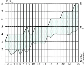
The results of the proposed EA were estimated for more than 100 digital circuits that required the considered above encoding technique within the respective process of synthesis. Fig. 1 shows these results for 25 FSMs. We considered block-based decomposition of FSMs [3], where R=intlog2M and Rav is an average number of
outputs for the blocks. So the considered technique makes possible the number of outputs required for each block to be decreased on average by 1.8.
1 2 3 4 5 6 7 8 9 10 12 14 16 18 20 22 25 1
2 3 4 5 6 7 8 R, Rav
Nu
m
b
er
o
f exam
p
les
R
Rav
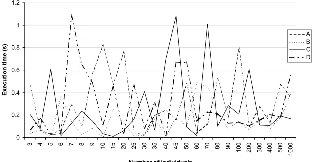
[image:7.612.233.377.493.607.2]The EA has been analyzed in several contexts. Firstly, we evaluated primary genetic operations that are reproduction (based on elitist rule and proportional selection criteria), mutation and crossover. The considered options A, B, C and D are listed below:
A: the crossover operation was carried out in order to form 90% of population for the next generation and 10% of population for the next generation was chosen with a probability based on fitness (i.e. based on proportional selection);
B: firstly the crossover operation was carried out in order to form 100% of population, secondly the mutation operation based on proportional selection was performed for 10% of individuals of the new generation and finally 10% of individuals in the next generation were replaced with 10% of randomly generated individuals;
C: the mutation operation based on proportional selection was carried out in order to form 100% of population for the next generation and 10% of individuals in the next generation were replaced with 10% of randomly generated individuals;
D: the crossover operation was carried out in order to form 90% of population for the next generation and 10% of population for the next generation was chosen based on elitist rule.
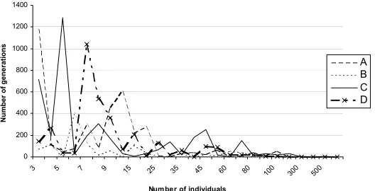
Fig. 2 shows how the execution time for all four options depends on the number of individuals in population. This dependency was considered for an FSM with 15 states (M=15) and with at maximum 4 transitions from each state. The experiments were performed on PentiumIII/800MHz/256MB. Fig. 3 shows how the number of required generations for all four options depends on the number of individuals in population.
0 0.2 0.4 0.6 0.8 1 1.2
3 4 5 6 7 8 9
10 15 20 25 30 35 40 45 50 60 70 80 90
100 200 300 400 500
1000
Number of individuals
Execut
ion t
ime (
s
)
A B C D
Fig. 2. Dependency of execution time on the number of individuals in population
[image:8.612.153.469.379.541.2]was chosen to be 15. Here NG is the number of generations, W is the optimal weight, We is the obtained weight, ET is the execution time, Gmin = max (intlog2|A(am)|),
m=1,...,M.
Thirdly, we performed a set of experiments for randomly generated examples with different initial data (such as the number of individuals in populations) and variable requirements (such as using one code for each state of FSM or employing more than one code for some states). Table 9 shows the best results for options A, B, C, D obtained for arbitrary selected examples (the option that gave the best result is indicated in the first column in parentheses). For the examples aex7 and aex8 just the option D was used and we received We<W because the value W cannot be obtained
when using just one code for each state. If we allow to employ more than one code for some states then the result with We=W can be easily found (ET = 41.12 s for
aex7 and ET = 9.38 s for aex8).
0 200 400 600 800 1000 1200 1400
3 5 7 9 15 25 35 45 60 80
100 300 500
Num ber of individuals
Num
b
er of
generat
ions
A B C D
Fig. 3. Dependency of the number of generations on the number of individuals in population
Table 8. The results of experiments for practical examples
Example NG W We ET (s) M Gmin
Ex1 134 32 32 0.424 20 2
Ex2 63 36 36 0.261 29 2
Ex3 99 7 7 0.202 12 4
[image:9.612.182.446.242.377.2]Ex4 111 30 30 0.255 15 2
Table 9. Experiments with arbitrary selected FSMs
Example NG W We ET (s) M Gmin
aex1 (B) 15 21 21 0.052 21 2
aex2 (B,D) 4 25 25 0.017 28 2
aex3 (D) 146 15 15 0.216 10 2
aex4 (B) 23682 34 34 61.767 15 3
aex5 (B) 490 31 31 3.897 47 2
aex6 (B) 12854 42 42 49.201 16 3
aex7 5534 88 87 1000 52 2
5 Conclusion
In the previous discussion we have presented the evolutionary algorithm for state encoding that allows Boolean functions to be decomposed in such a way that the dependency of sub-functions obtained as a result of the decomposition on the arguments can be reduced. The algorithm has been analyzed in several contexts. Firstly, we evaluated the primary genetic operations that are reproduction, mutation and crossover. Secondly, we examined practical applications that require the considered encoding technique. This enabled us to estimate some parameters, such as the expectable size of codes. Thirdly, we performed a set of experiments with different initial data (such as the number of individuals in populations) and variable requirements (such as using one code for each state of finite state machine or employing more than one code for some states). The examples in the paper and the results of experiments with a C++ program that implements the proposed evolutionary algorithm have shown that the considered approach is very effective.
References
1. S. Baranov, Logic Synthesis for Control Automata (Kluwer Academic Publishers, 1994). 2. V. Sklyarov, Reconfigurable models of finite state machines and their implementation in FPGAs, Journal of Systems Architecture, 47, 2002, pp. 1043-1064.
3. V. Sklyarov, Synthesis of Finite State Machines Based on Matrix LSI (Minsk, Science and Technique, 1984).
4. J. Torresen, Possibilities and Limitations of Applying Evolvable Hardware to Real-World Applications, Proceedings of FPL, Villach, Austria, August, 2000, pp. 230-239.
5. A. Thompson, P. Layzell, and R.S. Zebulum, Exploration in Design Space: Unconventional Electronics Design Through Artificial Evolution, IEEE Transactions on Evolutionary Computations, vol. 3, No. 3, September, 1999, pp. 167-176.
6. C. Manovit, C. Aporntewan, and P. Chongstitvatana, Synthesis of Synchronous Sequential Logic Circuits from Partial Input/Output Sequences, Proceedings of ICES'98, Evolvable Systems: From Biology to Hardware, Springer, N 1478, 1998, pp. 98-105.
7. H. Hemmi, J. Mizoguchi, and K. Shimohara, Development and Evolution of Hardware Behaviors, Toward Evolvable Hardware, Springer, N 1062, 1996, pp. 250-265.
8. J. Mizoguchi, H. Hemmi, and K. Shimohara, Production genetic algorithms for automated hardware design through an evolutionary process, IEEE Conference on Evolutionary Computations, 1994, pp. 250-265.
9. J.R. Koza, F.H. Bennet III, D. Andre, and M.A. Keane, Genetic Programming III
(Morgan Kaufmann Publishers, 1999).
10. J.F. Miller, P. Thomson, and T. Fogarty, Designing Electronic Circuits Using Evolu-tionary Algorithms. Arithmetic Circuits: A Case Study, Genetic Algorithms and Evolution Strategies in Engineering and Computer Science (John Wiley&Sons, 1998), pp. 105-131.