Analysis of time-dependent flexural behaviour of concrete members reinforced with fibre reinforced polymer bar
189
0
0
Texto completo
(2) Analysis of time-dependent flexural behaviour of concrete members reinforced with fibre reinforced polymer bars. Thesis submitted for the degree of Doctor of Philosophy by. Cristina Miàs i Oller 2012.
(3) Escola Politècnica Superior Departament d’Enginyeria Mecànica i de la Construcció Industrial DOCTORAL PROGRAMME IN TECHNOLOGY. Analysis of time-dependent flexural behaviour of concrete members reinforced with fibre reinforced polymer bars Cristina Miàs i Oller 2012 Thesis Supervisors: Dr. Lluís Torres Llinàs. Dr. Albert Turon Travesa. Universitat de Girona, Spain. Universitat de Girona, Spain. Thesis submitted for the degree of Doctor of Philosophy by the University of Girona.
(4)
(5) To whom it might concern,. Dr. Lluís Torres Llinàs and Dr. Albert Turon Travesa, Professors at the Universitat de Girona of the Department of Enginyeria Mecànica i de la Construcció Industrial,. CERTIFY that the study entitled Analysis of time-dependent flexural behaviour of concrete members reinforced with fibre reinforced polymer bars has been carried out under their supervision by Cristina Miàs Oller to apply the doctoral degree with the International Mention,. Girona, September 2012. Dr. Lluís Torres Llinàs. Dr. Albert Turon Travesa. Universitat de Girona, Spain. Universitat de Girona, Spain.
(6)
(7) Al meu avi i a tots els que brillen,.
(8) The present work has been funded by the Spanish Government (Ministerio de Ciencia e Innovación) under research grant BES-2008-005740. Also, it has been partially funded by the Spanish Government under research projects BIA2007-60222 and BIA2010-20234-C03-02.. The research stay of the author at the University of Sheffield at United Kingdom has been funded by the Spanish Government (Ministerio de Ciencia e Innovación) under grant SEST1000I000920XV0..
(9) This Ph.D. thesis has been prepared as a compendium of papers, according to the regulations of the University of Girona (Normativa d'ordenació dels ensenyaments universitaris de doctorat de la Universitat de Girona Aprovada pel Consell de Govern en la sessió 3/12, de 26 d'abril de 2012). The thesis includes four original papers: two papers that have already been published in peer-reviewed journals; one additional paper accepted, and another one that has already been submitted, which is under revision at the moment of preparing this document. The complete references of the papers comprised in this thesis, the impact factors, quartile, and category of the journals are:. - C. Miàs, Ll. Torres, A. Turon, M. Baena, C. Barris. A simplified method to obtain timedependent curvatures and deflections of concrete members reinforced with FRP bars, Composite Structures 2010; 92(8): 1833-38. doi: 10.1016/j.compstruct.2010.01.016 (Impact Factor: 2.24, journal 4 of 24, Quartile 1, Category: Materials Science, Composites). - Ll. Torres, C. Miàs, A. Turon, M. Baena. A rational method to predict long-term deflections of FRP reinforced concrete members, Engineering Structures 2012; 40:230-39. doi: 10.1016/j.engstruct.2012.02.021 (Impact Factor: 1.351, journal 22 of 118, Quartile 1, Category: Engineering, Civil). - C. Miàs, Ll. Torres, A. Turon, C. Barris. Experimental study of immediate and timedependent deflections of GFRP Reinforced concrete beams, Composite Structures, 2012 (in Press, Accepted Manuscript). doi: 10.1016/j.engstruct. 2012.08.052 (Impact Factor: 2.24, journal 4 of 24, Quartile 1, Category: Materials Science, Composites). -vii-.
(10) - C. Miàs, Ll. Torres, A. Turon, I. A. Sharaky. Effect of material properties on long-term deflections of GFRP reinforced concrete beams. Submitted to Construction and Building Materials Journal. (Impact Factor: 1.834, journal 8 of 56, Quartile 1, Category: Construction and Building Technology). The four papers have been published in (or submitted to) journals with impact factors within the first quartile, according to the 2011 Journal Citation Reports.. -viii-.
(11) Acknowledgements - Agraïments First and foremost I would like to thank my supervisors, Dr. Lluís Torres and Dr. Albert Turon, for giving me the opportunity to begin this trip together. Thanks for your guidance and your time during these last four years. Moltes gràcies per tot.. I would like to acknowledge the Department of Mechanical Engineering and Industrial Construction of the University of Girona, and particularity to the research group Analysis of Advanced Materials for Structural Design (AMADE) for the opportunity given.. I would also like to thank Dr. Kypros Pilakoutas, Dr. Maurizio Guadagnini and Dr. Kyriakos Neocleous for their support during my research stay at the University of Sheffield.. M’agradaria també donar les gràcies a aquells que han col·laborat en la realització dels assajos experimentals, especialment a la Marta Baena, Irene Vilanova i Cristina Barris; tot i la tensió dels assajos, juntes hem rigut i compartit bons moments! Jordi Vicens i Sergi Saus, sense la vostra “força bruta” i la vostra inventiva aquests assajos no haurien estat possible, mil gràcies.. Gràcies a la gent d’AMADE per l’ajuda i els bons moments que hem compartit. Gràcies a tots, als que encara avui en formeu part i als que heu marxat a buscar nous horitzons, E.V. González, J. Bonilla, P. Vicens, E. Pajares, D. Sans, P. Badalló, M. Gascons, J. Bofill, N. Hereu, D. Piedrafita, C. Sarrado, L. Zubillaga, J. Vives, L. Marín, X. Cahís, M. Llorens , N. Gascons, S. Ortiz... i aquells qui un temps enrere van fer que el projecte AMADE fos possible: J. Costa, J.A. Mayugo, A. Turon, D. Trias, P. Maimí, N. Blanco, J. Renart.. -ix-.
(12) A la Dolors i la Montse per fer que els migdies també siguin moments especials.. Al meus amics, a tots, per fer-me sentir sempre a prop vostre, gràcies Anna, Susagna, Maria, Sergi, Josep i Maria, Albert, Tere i a tota la colla al complet!. A la meva família. A la Judith, per ser com és. A la meva àvia, per estar sempre al meu costat. Als meus pares, gràcies mare per aquest suport incondicional que sempre m’has donat (entre tu i jo, t’estimo molt); gràcies Rafael pels valors que m’has transmès.. Per últim gràcies a tu, si Joan, a tu, per tot el que hem compartit i espero continuar compartint (quilòmetres per recórrer...).. -x-.
(13) Summary In the past two decades, a large number of research programmes focussed on short-term flexural behaviour of fibre reinforced polymer (FRP) reinforced concrete (RC) members has been carried out. However the number of studies on the long-term behaviour of FRP reinforced concrete members is still scarce. In this work, long-term behaviour of FRP RC beams has been investigated both analytically and experimentally to further extend the knowledge in this particular research domain. In this respect, a new methodology to determine the long-term deflections due to creep and shrinkage is presented. Based on multiplicative coefficients, the methodology is straightforward and simple, and therefore suitable to be used in design. In addition, an experimental campaign on two series of GFRP RC beams subject to long-term loading has been performed. Different reinforcement ratios, concrete strengths and sustained load levels have been considered. For comparison purposes steel reinforcement has also been used. The experimental long-term results have been reported and discussed. Furthermore they have been compared to predictions using the most representative procedures, as well as, the proposed methodology presented in this work.. -xi-.
(14) Resum. En les últimes dues dècades, han aparegut nombrosos estudis centrats en el comportament instantani a flexió de bigues de formigó armades amb materials compostos. No obstant això, els estudis referents al comportament a llarg termini encara són escassos. En aquest treball, s’investiga el comportament a llarg termini de bigues armades amb barres de material compost, tant des del punt de vista analític com experimental, amb l’objecte d’ampliar així aquest camp d’estudi. En aquest sentit es presenta una nova metodologia per a la determinació de fletxes diferides degudes als efectes de la fluència i la retracció del formigó. La metodologia presentada es basa en coeficients multiplicadors, essent així un mètode directe i simple, apte per ser utilitzar en el disseny. Addicionalment, l’estudi presenta els resultats d’una campanya experimental realitzada en dues etapes, on bigues armades amb barres de material compost amb fibra de vidre (GFRP) han estat sotmeses a càrregues a llarg termini. S’han considerat diferents quanties de reforç, resistències de formigó i nivells de càrrega. Per tal de comparar-ne els resultats, també s’han assajat bigues armades amb barres d’acer. Els resultats experimentals han estat analitzats i comparats amb els models de predicció més significatius, així com amb la metodologia desenvolupada i presentada en aquest estudi.. -xii-.
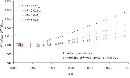
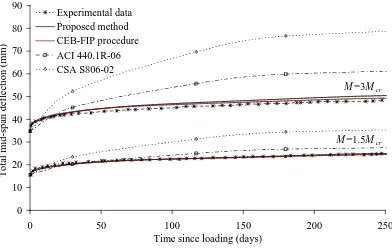
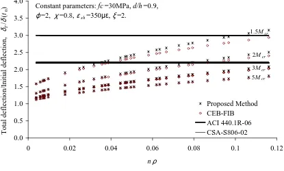
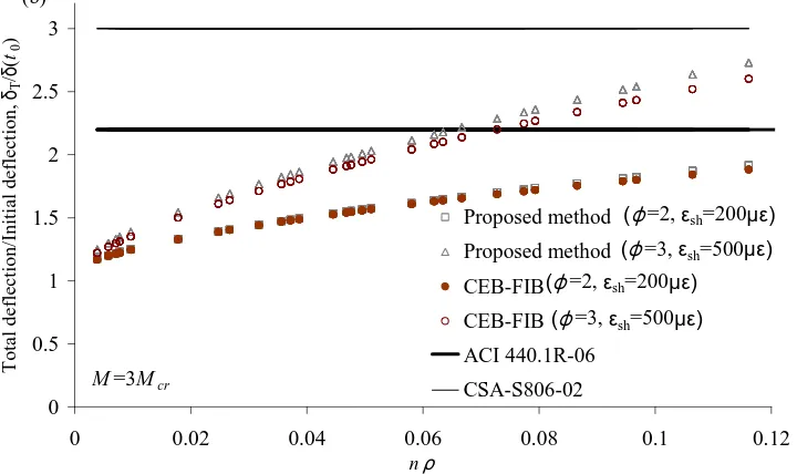
(15) List of Figures. Figure 2.1. Instantaneous and long-term strains and curvatures in a cracked section ............. 17 Figure 2.2. (a) Multiplicative coefficient kcreep and (b) relative error between analytical procedure, Eq.(13), and proposed method, Eq.(18). ................................................................ 21 Figure 2.3. Comparison of the proposed coefficient kcreep and the coefficient obtained using the CEB [17], ϕ (t , t0 )κ ϕ , 2 . ........................................................................................................ 23 Figure 2.4. Relationship between Ms/Mcr and nρ for FRP reinforced concrete beams. ......... 27 Figure 2.5. Error made using the proposed method to calculate the total deflection for different. levels of concrete shrinkage. ................................................................................. 28. Figure 2.6. Comparison of the predicted total mid-span deflection using different methods.. 30 Figure 3.1.. Ratio between total curvatures predicted using. (Eq. 18) and Eurocode 2,. ψ T (t , t 0 ) proposed ,............................................................................................................................. 50 ψ T (t , t 0 ) EC −2. Figure 3.2. Comparison of experimental data with the predicted total mid-span .................... 59 Figure 3.3 Effect of applied moment on the total-to-initial deflection prediction ratio,. δT. δ (t 0 ). .. .................................................................................................................................................. 60 Figure 3.4. Effect of the free shrinkage strain and creep coefficient on the total-to-initial deflection prediction ratio. δT . Applied moments: (a) M=1.5Mcr , (b) M=3Mcr. .............. 62 δ (t0 ). Figure 4.1. Geometric details of the tested beams. .................................................................. 83 Figure 4.2. Experimental set-up (a) instantaneous loading tests (b) sustained loading test..... 85 Figure 4.3. Load mid-span deflection curves for beams N_G12. ........................................... 87. -xiii-.
(16) Figure 4.4. Load mid-span deflection curves for beams N_G16. ........................................... 87 Figure 4.5. Total deflections for (a) beams reinforced with 2Ø12 GFRP bars ........................ 95 Figure 4.6.Total deflections for beams: (a) N_L1_G12a (b) N_L2_G12a. ............................ 99 Figure 4.7. Total deflections for beams: (a) N_L1_G16a (b) N_L2_G16a. ......................... 100 Figure 5.1. Geometric details of the tested beams ................................................................. 114 Figure 5.2. (a) Cylindrical moulds (b) cylindrical mould for the creep coefficient determining with embedded strain gauge (c) set-up for creep tests on cylinders....................................... 117 Figure 5.3. Set-up for long-term tests .................................................................................... 119 Figure 5.4. Temperature and relative humidity registered in the laboratory during N_beams tests......................................................................................................................................... 121 Figure 5.5. Temperature and relative humidity registered in the laboratory during H_beams tests......................................................................................................................................... 121 Figure 5.6. Experimental free shrinkage strain – Concrete of N_beams series ..................... 122 Figure 5.7. Experimental free shrinkage strain – Concrete of H_beams series ..................... 123 Figure 5.8. Experimental creep coefficient – Concrete of N_beams series ........................... 124 Figure 5.9. Experimental creep coefficient – Concrete of H_beams series ........................... 125 Figure 5.10. Total deflections for N_beams reinforced with (a) 2Ø12 GFRP, (b) 2Ø16 GFRP, (c) 2Ø10 steel bars.................................................................................................................. 129 Figure 5.11. Total deflections for H_beams reinforced with (a) 2Ø12 GFRP, (b) 2Ø16 GFRP, (c) 2Ø10 steel bars.................................................................................................................. 130 Figure 5.12. Total deflections versus time since loading for beams. (a) N_L1_G12 (b). N_L2_G12.............................................................................................................................. 135 Figure 5.13. Total deflections versus time since loading for beams (a) H_L1_G12 beams and (b) H_L2_G12 beams (c) H_L1_G16 beams and (d) H_L2_G16 beams ............................. 138. -xiv-.
(17) List of Tables. Table 2.1. Predicted/Experimental deflections ........................................................................ 32 Table 3.1. Ratio between total curvatures predicted using Eq. (18) and Eurocode 2, ψ T (t , t 0 ) proposed , for different environmental conditions (f =30MPa)........................................... 51 c ψ T (t , t 0 ) EC −2. Table 3.2. Comparison of the total-to-initial deflection prediction ratio,. δT. δ (t 0 ). , for M=1.5Mcr.. Constant parameters: fc=30MPa, d/h=0.9, ξ =2. ...................................................................... 64 Table 3.3. Comparison of the total-to-initial deflection prediction ratio,. δT. δ (t 0 ). , for M=3Mcr.. Constant parameters: fc=30MPa, d/h=0.9, ξ =2. ...................................................................... 65 Table 4.1. Geometric properties of beams. ............................................................................. 83 Table 4.2. Mechanical properties of GFRP rebars. ................................................................. 84 Table 4.3. Applied sustained load, Psus. ................................................................................... 86 Table 4.4. Experimental deflections at load Psus. ..................................................................... 89 Table 4.5. Comparison of deflections corresponding to load P. .............................................. 91 Table 4.6. Instantaneous deflections corresponding to load Psus ............................................. 92 Table 4.7. Immediate deflection corresponding to load Psus after cycling............................... 93 Table 4.8. Ratio between total deflection and immediate deflection. ..................................... 96 Table 4.9. Comparison between total deflections and analytical predictions using CSA-S80602 approach (Eq. (8)). Time since loading: 180 days. ........................................................... 101 Table 4.10.. Comparison between total deflections and analytical predictions using ACI. 440.1R-06 approach (Eq. (7)). Time since loading: 180 days. .............................................. 101. -xv-.
(18) Table 5.1. Beams designation ................................................................................................ 115 Table 5.2. Composition of concrete ....................................................................................... 116 Table 5.3. Concrete mechanical properties ............................................................................ 117 Table 5.4. Mechanical properties of GFRP rebars. Values provided by manufacturer in brackets................................................................................................................................... 118 Table 5.5. –. Maximum instantaneous loads, P, and sustained loads, Psus,. applied on. N_beams series....................................................................................................................... 120 Table 5.6. Maximum instantaneous loads, P, and sustained loads, Psus, applied on H_beams ................................................................................................................................................ 120 Table 5.7. Experimental time-dependent concrete properties (average values). ................... 126 Table 5.8. Ratio between the total and immediate deflection for N_beams .......................... 131 Table 5.9. Ratio between the total and immediate deflection for H_beams .......................... 131 Table 5.10. Ratio between theoretical and experimental total deflection at 250 days since loading (N_beams). ................................................................................................................ 136 Table 5.11. Ratio between theoretical and experimental total deflection at 700 days since loading (H_beams). ................................................................................................................ 139. -xvi-.
(19) Contents. Summary/Resum ..................................................................................................................... xi List of Figures ........................................................................................................................xiii List of Tables........................................................................................................................... xv 1.. Introduction and objectives ............................................................................................. 1 1.1 1.2 1.3. 2.. Introduction ................................................................................................................. 3 Objectives .................................................................................................................... 5 Outline of the thesis..................................................................................................... 6. A simplified method to obtain time-dependent curvatures and deflections of. concrete members reinforced with FRP bars ........................................................................ 9 2.1 2.2. Introduction ............................................................................................................... 13 Prediction of time-dependent curvatures based on.................................................... 15. Eurocode 2 .......................................................................................................................... 15 2.3 Prediction of time-dependent curvature due to creep ................................................ 16 2.3.1 Time-dependent curvature due to creep in cracked sections..................................... 16 2.3.2 Derivation of a simplified method to obtain long-term curvature due to creep ........ 19 2.3.3 Comparison with other methods................................................................................ 22 2.4. Prediction of total deflections.................................................................................... 24. 2.4.1 Simplified method to obtain total deflections............................................................ 24 2.4.2 Application range of the simplified method to obtain total deflections .................... 26 2.5 2.6 2.7. Comparison with experimental data .......................................................................... 29 Conclusions ............................................................................................................... 31 Acknowledgements ................................................................................................... 33. 2.8. References ................................................................................................................. 34. -xvii-.
(20) 3.. A rational method to predict long-term deflections of FRP. reinforced concrete. members .................................................................................................................................. 37 3.1 3.2. Introduction ............................................................................................................... 41 Time-dependent coefficients for FRP RC beams ...................................................... 43. 3.2.1 Long-term curvature due to creep ............................................................................. 44 3.2.2 Long-term curvature due to shrinkage....................................................................... 46 3.2.3 Comparison of the proposed coefficients and the reference analytical procedure .... 49 3.2.4 Long-term deflection due to creep and shrinkage ..................................................... 52 3.3. Evaluation of total deflections of FRP RC members ................................................ 54. 3.3.1 Prediction models ...................................................................................................... 54 3.3.2 Proposed method ....................................................................................................... 57 3.3.3 Comparison with experimental data .......................................................................... 57 3.3.4 Comparison of methodologies for deflection prediction........................................... 59 3.4 3.5 3.6 3.7 4.. Conclusions ............................................................................................................... 66 Acknowledgements ................................................................................................... 67 Appendix. Generalized coefficient for long-term curvatures due to creep ............... 68 References ................................................................................................................. 73. Experimental study of immediate and time-dependent deflections of GFRP. reinforced concrete beams..................................................................................................... 77 4.1 4.2. Introduction ............................................................................................................... 81 Test specimens and materials .................................................................................... 82. 4.2.1 Beams specifications ................................................................................................. 82 4.2.2 Material properties..................................................................................................... 84 4.2.3 Test set-up.................................................................................................................. 84 4.3. Test results and discussion ........................................................................................ 86. 4.3.1 Short-term deflections ............................................................................................... 86. -xviii-.
(21) 4.3.2 Short-term deflection prediction................................................................................ 89 4.3.3 Time-dependent deflections ...................................................................................... 94 4.3.4 Prediction of time-dependent deflections .................................................................. 96 4.4 4.5 4.6 5.. Conclusions ............................................................................................................. 102 Acknowledgements ................................................................................................. 103 References ............................................................................................................... 104. Experimental long-term deflections of GFRP reinforced concrete beams under. sustained loading .................................................................................................................. 107 5.1 5.2. Introduction ............................................................................................................. 111 Experimental test program....................................................................................... 114. 5.2.1 Beams specifications ............................................................................................... 114 5.2.2 Material properties................................................................................................... 116 5.2.3 Experimental set-up................................................................................................. 118 5.3. Experimental results ................................................................................................ 122. 5.3.1 Time-dependent effects of concrete ........................................................................ 122 5.3.2 Experimental time-dependent deflections ............................................................... 126 5.4 5.5 5.6 5.7 5.8 6.. Design methodology for long-term deflections........................................................... 149 6.1 6.2 6.3. 7.. Comparison with analytical models ........................................................................ 132 Conclusions ............................................................................................................. 139 Acknowledgements ................................................................................................. 140 Appendix ................................................................................................................. 141 References ............................................................................................................... 145. Calculation of long-term deflections ....................................................................... 151 Examples ................................................................................................................. 153 References ............................................................................................................... 160. Conclusions.................................................................................................................... 161 7.1. Summary.................................................................................................................. 163. -xix-.
(22) 7.2 7.3. Concluding Remarks ............................................................................................... 164 Future Work............................................................................................................. 166. -xx-.
(23) 1. Introduction and objectives.
(24)
(25) Chapter 1 Introduction and objectives. 1.1 Introduction Fibre reinforced polymer (FRP) bars have emerged as an alternative to steel reinforcement in concrete structures such as seawalls and other marine structures as well as bridge decks, superstructures and pavements exposed to de-icing salts. FRP materials exhibit properties such as corrosion resistance and high tensile strength that make them suitable for this type of structures. In addition, due to their nonconductive properties, FRP materials are also used in concrete structures supporting magnetic resonance imaging units, railway magnetic levitation systems or other equipment sensitive to electromagnetic fields.. FRP bars are made of continuous fibres impregnated with polymeric matrix (also referred as resin). The most common fibre types used in the construction industry are glass, carbon, and aramid. Recently, basalt fibres have also been commercially available. On the other side, the matrix in a polymeric composite can be regarded as both a structural and a protection component. There are two basic types of polymeric matrices used in FRP composites: thermosetting and thermoplastic resins. Generally, thermosetting resins, such as epoxy and vinyl ester are the most used in the construction industry.. FRP bars are anisotropic with higher modulus in the direction of the reinforcing fibres, and are characterized by linear behaviour up to failure, without yielding. Compared to ductile steel, FRP bars generally have higher tensile capacity, limited strain range and lower modulus of elasticity. Steel reinforced concrete sections are commonly under-reinforced to ensure yielding of steel before the crushing of concrete, thus providing ductility and a warning of failure. The non-ductile behaviour of FRP reinforcement makes the concrete crushing the design driving failure mode for flexural members reinforced with FRP bars. Proposed formulations for the design of FRP reinforced concrete (RC) structures are based on the same principles already established for steel RC structures. Nevertheless, the equations derived for steel RC structures have been adapted to the particular behaviour of FRP RC members. In general, due to the lower elastic modulus of FRP bars, the design of FRP RC members is. -3-.
(26) Chapter 1 Introduction and objectives. likely to be governed by the serviceability limit states, where deflection control is usually expected to be a limiting factor. In the past two decades, a large amount of studies focussed on bending, shear and FRP-concrete bond have been carried out. A better understanding of short-term behaviour of FRP RC members is now available and collected in the recent literature. However very little published information is focussed on long-term deflections and further experimental works is necessary, as recognized by some existing guidelines (ACI 440.1R-06).. To address long-term deflections due to creep and shrinkage, available guidelines for FRP RC structures, such as ACI 440.1R-06 and CSA-S-806-02, propose simplified procedures based on empirical multiplicative coefficients. These approaches are simple and straightforward but do not account for variations in mechanical properties of materials and environmental conditions. This fact could be of major importance for FRP RC structures where the mechanical properties of the reinforcement can change when using different types of fibres.. On the other hand, using more general methodologies, such as the Effective Modulus Method (EMM) and the Age-Adjusted Effective Modulus Method (AEMM), allows the mechanical behaviour of materials to be taken into account in a more rational way. These methods take into account some of the main parameters involved in the time-dependent behaviour, such as, member geometry, load characteristics (magnitude and duration of load, age of concrete at the time of loading), and material properties (elastic modulus of concrete and FRP reinforcement, creep and shrinkage of concrete). However, complexity is introduced into the calculation.. Therefore, a deep understanding of the main parameters involved in long-term deflections is needed. In addition, a straightforward methodology to computed long-term deflections accounting for the main influencing parameters should be addressed.. -4-.
(27) Chapter 1 Introduction and objectives. 1.2 Objectives The overall objective of this work is to investigate the long-term behaviour of FRP RC beams, both analytically and experimentally.. The first objective of this work is to develop a methodology to predict long-term deflections due to creep and shrinkage. This methodology must be simple, however it must account for mechanical properties of materials and environmental conditions. In addition, since the number of tests regarding the long-term behaviour of FRP reinforced concrete members is still scarce, the second objective of this work is to further extend the experimental data in this particular research domain.. For this purpose, the specific objectives addressed in this study are:. -. To obtain a methodology that could be used in design to determine the long-term curvatures and deflections due to creep and shrinkage phenomena.. -. To compare the proposed methodology to available prediction models, varying different parameters that can influence the results: applied loads, reinforcement ratios, concrete strength, elastic modulus of reinforcement, creep coefficient and shrinkage strain.. -. To carry out an experimental campaign on FRP RC beams with different concrete strengths, different reinforcement ratios, and under different levels of sustained load to study the long-term behaviour under the serviceability requirements.. -. To compare the experimental results to the available models, and to examine the ability for prediction of the different existing approaches.. -. To compare the experimental results of long-term deflections to the proposed methodology and check its suitability.. -. To provide a convenient design methodology for the assessment of long-term deflections of FRP RC members. .. -5-.
(28) Chapter 1 Introduction and objectives. 1.3 Outline of the thesis The body of this dissertation consists on the four aforementioned manuscripts, which are included in the following chapters. In Chapter 2, a straightforward and simple methodology to compute the long-term curvatures and deflections, due to creep, from initial curvatures and deflections is presented. The procedure is based on the multiplicative coefficient kcreep. The coefficient is deduced considering the principles of the Effective Modulus Method for a fully-cracked section, and it is reduced by mathematical manipulation to be simple but also able to account for variations in the environmental conditions and mechanical properties of materials. Comparison of predictions using the proposed methodology with existing procedures, as well as with experimental results is done and discussed in terms of serviceability conditions. In Chapter 3, the proposed multiplicative coefficient to obtain long-term deflections due to creep is generalized to take into account the tension-stiffening effect, expanding its applicability. In addition, a multiplicative coefficient to compute long-term deflections due to shrinkage is deduced from general principles of structural mechanics and using the Effective Modulus Method. Predictions obtained using both proposed coefficients are compared to experimental results to show their suitability, and to available procedures to highlight the influence of different parameters in predictions.. Chapter 4 presents the experimental programme and its results concerning GFRP RC beams tested at service load and subsequently subjected to different levels of sustained load for 250 days. The effects of the loading-unloading processes and the reinforcement ratios on immediate and long-term deflections are discussed. Analytical comparisons between the experimental data and some of the most representative prediction models are presented and analysed.. -6-.
(29) Chapter 1 Introduction and objectives. Chapter 5 presents an experimental test programme which complements the results presented in Chapter 4. The influence of concrete strength, as well as that of reinforcement ratio on long-term deflections of GFRP RC beams is analysed. Theoretical predictions using available procedures specific for FRP RC members are calculated and compared to obtained experimental long-term deflections. In addition, the experimental data are compared to the methodology proposed in Chapters 2 and 3.. -7-.
(30)
(31) 2. A simplified method to obtain time-dependent curvatures and deflections of concrete members reinforced with FRP bars. -9-.
(32)
(33) Chapter 2 A simplified method to obtain time-dependent curvatures and deflections of concrete members reinforced with FRP bars. C. Miàs, Ll. Torres, A. Turon, M. Baena, C. Barris. A simplified method to obtain timedependent curvatures and deflections of concrete members reinforced with FRP bars, Composite Structures 2010; 92: 1833-38. doi: 10.1016/j.compstruct.2010.01.016. Summary: The design of concrete beams reinforced with fibre reinforced polymer (FRP) bars is often governed by the serviceability limit state, in which deflections play an important role. One of the most straightforward and easiest methods for calculating time-dependent deflections is based on applying multiplicative coefficients to instantaneous deflections. These methods have been adopted by ACI.440.1R-06 and CSA-S806-02 for FRP reinforced concrete structures (RCS), introducing slight modifications with respect to steel reinforced concrete members. However, the influence of different material mechanical properties and environmental conditions are not accounted for properly. In this paper, a new method based on a simplified coefficient for the prediction of time-dependent deflections is presented. The influence of variations in environmental conditions and the mechanical properties of the materials are taken into account. The numerical predictions obtained are compared to other models available in the literature and experimental results to validate the accuracy and suitability of the methodology presented.. -11-.
(34)
(35) Chapter 2 A simplified method to obtain time-dependent curvatures and deflections of concrete members reinforced with FRP bars. 2.1 Introduction Fibre reinforced polymers (FRP) are increasingly used as an alternative to steel reinforcement in corrosive environments or where there is a possible interference from magnetic fields, which can cause problems if conventional reinforced concrete structures are used. Due to the lower stiffness of FRP bars compared to steel, the design of concrete beams reinforced with FRP materials is often governed by the serviceability limit state, in which deflections play an important role.. Several methods have been developed for time-dependent analysis of reinforced concrete structures which have been proved to be able to predict the long-term deflections of steel reinforced concrete members due to creep and shrinkage: the Effective Modulus Method, the Mean Stress Method and the Age-Adjusted Effective Modulus Method, among others (Gilbert [1], Bazant [2], Chiorino [3]). These methods take into account some of the main parameters involved in the time-dependent behaviour of reinforced concrete structures, such as the properties of the materials (reinforcement and concrete) and the influence of environmental conditions by introducing the creep and shrinkage values of concrete. Using these methods, accurate predictions can be obtained and consequently the Effective Modulus Method and the Age-Adjusted Effective Modulus Method have been adopted in some national and international codes and recommendations, such as Eurocode 2 [4], Model Code 90 [5], and ACI 435 [6]. Nevertheless, the use of even more simplified procedures for practical design based on multiplicative coefficients has been widespread, and due to their straightforwardness they are probably the most popular (ACI 318 [7]). In these simplified procedures, time-dependent deflections of steel reinforced concrete structures (SRCS) are obtained by multiplying the short-term deflection due to sustained loads by an appropriate factor. Although these procedures are practical and easy to use, they do not take into account the influence of. -13-.
(36) Chapter 2 A simplified method to obtain time-dependent curvatures and deflections of concrete members reinforced with FRP bars. different material properties, mainly the creep and shrinkage of concrete, or the influence of using different reinforcing materials such as FRP.. FRP reinforced concrete structures (FRPRCS) develop larger deformations than steel reinforced members under the same conditions (concrete class, dimensions and area of reinforcement). The sectional curvatures and the tensioned area are larger, while the compressed area is smaller. In terms of time-dependent behaviour, the relative curvature increment associated with creep and shrinkage is lower than for conventional SRCS due to the smaller compressed area of concrete, and therefore lower time-dependent deflections are expected in FRPRCS. Hence, ACI 440.1R-06 [8], based on tests carried out by Brown and Bartholomew [9] and Brown [10], proposes multiplying the factor used for SRCS by 0.6, although the code recognizes that further work is necessary to validate the coefficient. However, the Canadian standard CSA S806-02 [11] proposes a more conservative approach, adopting the same coefficients as for steel.. Some other studies reported experimental work and analytical proposals on this topic. Arockiasamy et al. [12] proposed a multiplicative factor for long-term deflections based on a modification of the ACI 318 procedure [7]. The values of the coefficient were adjusted to their experiments on CFRP reinforced concrete beams. Hall and Ghali [13] compared their experimental long-term deflections of GFRP reinforced concrete beams with the predicted deflections using the procedures of ACI Committee 209 [14] and the CEB-FIB Model Code 1990 [5] with the equations found in Ghali and Favre [15]. They concluded that while ACI Committee 209 overestimated the experimental deflections, CEB-FIB Model Code 1990 gave reasonable predictions. Also the effect of different environmental conditions on the creep behaviour of concrete beams reinforced with GFRP bars under sustained loads was investigated by Al-Salloum and Almusallam [16]. The experimental results showed a strong significant influence of the environmental conditions.. This article proposes a new multiplicative coefficient to predict time-dependent curvatures in. -14-.
(37) Chapter 2 A simplified method to obtain time-dependent curvatures and deflections of concrete members reinforced with FRP bars. FRPRCS based on the principles of the Effective Modulus Method and Eurocode 2 [4]. The proposed coefficient is intended to be simple but also able to account for variations in the environmental conditions and mechanical properties of materials. Simplified equations for deflection calculation are deduced and verified for the most common case of simply supported FRPRC beams.. 2.2 Prediction of time-dependent curvatures based on Eurocode 2 Based on Eurocode 2 [4], the curvature, ψ , in members subjected to flexure, which are expected to crack but may not be fully cracked, can be calculated by:. ψ = (1 − ξ )ψ 1 + ξψ 2 M ξ = 1 − β cr M . (1). 2. (2). where the subscripts 1 an 2 refer to the uncracked and fully cracked conditions respectively;. ξ is an interpolation coefficient to account for tension stiffening; Mcr is the cracking moment; M is the applied moment; and β is a coefficient taking account of the influence of the duration of loading (1 for a single short-term load, and 0.5 for sustained or repeated loads).. The long-term curvature will increase due to the effects of creep and shrinkage of concrete. For sustained loads, the total curvature including creep, ψ * (t , t 0 ) , can be calculated by using an effective modulus of elasticity for concrete according to the following expression:. Ec (t , t0 ) =. Ec (t0 ) 1 + ϕ (t , t0 ). (3). where Ec (t0 ) is the elastic modulus of concrete at the time t0 and ϕ (t , t0 ) is the creep coefficient that depends on time and duration of loading.. -15-.
(38) Chapter 2 A simplified method to obtain time-dependent curvatures and deflections of concrete members reinforced with FRP bars. The curvature due to shrinkage, ∆ψ sh (t , t0 ) , can be obtained by: ∆ψ sh (t , t0 ) = ε sh (t , t 0 )n(t , t 0 ). S I. (4). where ε sh (t , t 0 ) is the free shrinkage strain at the time t, S is the first moment of area of the reinforcement about the centroid of the section, I is the second moment of area of the section, and n(t , t 0 ) is the effective modular ratio: n(t , t 0 ) =. Es Ec (t , t 0 ). (5). with Es being the elastic modulus of steel. S and I should be calculated for an uncracked and a fully cracked condition, and the final curvature should be assessed by using Eq. (1).. The basis of this procedure is general for reinforced concrete structures (SRCS, FRPRCS) because it incorporates the main influencing parameters.. 2.3 Prediction of time-dependent curvature due to creep. 2.3.1 Time-dependent curvature due to creep in cracked sections A fully cracked FRP reinforced concrete section subjected to a bending moment is analysed. Concrete in tension is not considered. It is not recommended to rely on FRP bars to resist compressive stresses and they should be ignored in design calculations [8], therefore the compressive reinforcement is not taken into account in this study.. According to Eq. (3) the effective concrete elastic modulus, Ec (t , t0 ) , decreases due to creep at a rate of (1 + ϕ (t , t0 ) ) . Therefore, the depth of the compression zone of a cracked section. -16-.
(39) Chapter 2 A simplified method to obtain time-dependent curvatures and deflections of concrete members reinforced with FRP bars. subjected to a constant bending moment increases with time to achieve equilibrium, and so does curvature, as shown in Figure 2.1.. ε(t,t0 ) ε(t0) ψ2∗(t 0) ψ2∗(t,t 0). h d. x(t,t0 ) x (t 0 ). b. Af. Cracked section. Strains. Figure 2.1. Instantaneous and long-term strains and curvatures in a cracked section. Assuming that the total curvature in a fully cracked section, including the creep effect, is equal to:. ψ 2* (t , t0 ) = ∆ψ 2,creep (t , t0 ) + ψ 2 (t0 ). (6). the relative increment of curvature due to creep can be determined as: ∆ψ 2,creep (t , t 0 ). ψ 2 (t 0 ). ψ 2* (t , t 0 ) = −1 ψ 2 (t 0 ). (7). where ∆ψ 2,creep (t , t 0 ) is the curvature due to creep, and ψ 2 (t 0 ) the instantaneous curvature.. -17-.
(40) Chapter 2 A simplified method to obtain time-dependent curvatures and deflections of concrete members reinforced with FRP bars. Assuming that the section is subjected to a constant bending moment, the ratio of curvatures is equal to the ratio between sectional stiffness k 2 (t , t 0 ) and k2(t0): M ψ (t , t 0 ) k 2 (t , t 0 ) k (t ) = = 2 0 M ψ 2 (t 0 ) k 2 (t , t 0 ) k 2 (t 0 ) * 2. (8). The sectional stiffness of a fully cracked section reads: k2 = E f A f (d − x)(d − x / 3). (9). where Af is the area of tensile reinforcement; d is the effective depth; x is the neutral axis depth of the section; and Ef is the elastic modulus of FRP reinforcement. Because of the low level of stress imposed on FRP reinforcement by serviceability conditions [8], the effect of the possible creep deformation of the bar is ignored in front of the greater influence of concrete creep.. Using Eqs. (7), (8), and (9), the relative increment of curvature can be written as: ∆ψ 2,creep (t , t 0 ). ψ 2 (t 0 ). x(t0 ) x(t 0 ) 1 − 1 − d 3d = −1 x(t , t0 ) x(t , t 0 ) 1 − 1 − d 3d . (10). In the absence of compressive reinforcement, the neutral axis depth for a fully cracked section at the initial time, x(t0 ) , can be written as:. x(t 0 ) = n(t 0 ) ρ − 1 + d . 2 1 + n(t 0 ) ρ . (11). where n(t0 ) is the ratio between the elastic modulus of reinforcement and concrete, and ρ is the reinforcement ratio.. -18-.
(41) Chapter 2 A simplified method to obtain time-dependent curvatures and deflections of concrete members reinforced with FRP bars. A similar equation can be written to obtain the neutral axis depth at time t, x(t , t0 ) , taking into account the influence of concrete creep with the use of the corresponding coefficient ϕ (t , t0 ) :. x(t , t0 ) = n(t0 )(1 + ϕ (t , t0 ) )ρ − 1 + d . 2 1 + n(t0 )(1 + ϕ (t , t0 ) )ρ . (12). Using Eqs. (11) and (12) in Eq. (10), the relative increment of curvature reads: 1 − nρ − 1 + 1 + 2 1 − nρ − 1 + 1 + 2 nρ nρ 3 ∆ψ 2,creep (t , t 0 ) = −1 ψ 2 (t 0 ) nρ (1 + ϕ ) 2 2 1 − nρ (1 + ϕ ) − 1 + 1 + 1 − −1 + 1 + + + ( ) n ρ ϕ n ρ ( ϕ ) 1 3 1 (13). For the sake of simplicity in Eq.(13), n refers the coefficient between the elastic modulus of the reinforcement and the elastic modulus of concrete at the initial time of n(t0 ) , and ϕ is the creep coefficient ϕ (t , t 0 ) between t and t0.. 2.3.2 Derivation of a simplified method to obtain long-term curvature due to creep In this section a multiplicative factor, k creep , is deduced to obtain long-term curvature due to creep, ∆ψ 2,creep (t , t0 ) , from the initial curvature, ψ 2 (t0 ) , so that: ∆ψ 2,creep (t , t0 ) = k creepψ 2 (t 0 ). (14). The coefficient k creep has been deduced using mathematical methods of simplification. In order to mathematically manipulate the expression given in Eq. (13),. -19-. ∆ψ 2,creep (t , t0 ). ψ 2 (t 0 ). is.
(42) Chapter 2 A simplified method to obtain time-dependent curvatures and deflections of concrete members reinforced with FRP bars. renamed as f (r , t ) , nρ as r2 and ϕ as t. Therefore, Eq. (13) can be rewritten as:. 2 1 − r 2 − 1 + 1 + 22 1 − r − 1 + 1 + 22 r r 3 f (r , t ) = −1 2 r t + 2 1 2 ( ) 1 − r 2 (1 + t ) − 1 + 1 + 1 − −1 + 1 + 2 2 ( ) ( ) + r t r t + 1 3 1 . (15). The adimensional parameter nρ depends on the elastic moduli of FRP and concrete, and the amount of tensile reinforcement. The elastic modulus of FRP usually ranges between 40 and 120GPa (the lowest values for GFRP, medium values for AFRP and the largest for CFRP). The usual values for concrete strength are between 20 and 80MPa, and for a reinforcement ratio ρ between 0 and 0.04. For concrete beams reinforced with FRP bars, it can therefore be assumed that nρ usually ranges between 0 and 0.2. The creep coefficient, ϕ , depends on the loading age, the ambient humidity, element dimensions and the composition of the concrete. Assuming an interval of variation from 1 to 3, a wide range of environmental conditions are taken into account.. Assuming, therefore, that the usual values for nρ and φ can range from 0 to 0.2 and from 1 to 3 respectively, the Taylor series development of Eq. (15) has been developed about the point (0,2).. f (r , t ) = − Like. 4 22 64 32 8 6rt + .... 2r + 6r − 3r 2 + r 2 + 3 27 27 9 27. (. (16). ). 4 64 32 2 22 r + 6r ∀r ∈ 0, 0.3 , Eq. (16) can be approximated as: 2r + 3r 2 ≈ 3 27 9 27 f (r ,ϕ ) =. 8 t 6r 27. (17). -20-.
(43) Chapter 2 A simplified method to obtain time-dependent curvatures and deflections of concrete members reinforced with FRP bars. Therefore, the simplified coefficient k creep can be defined as: k creep = 0.73ϕ nρ. (18). It is noteworthy that the proposed coefficient, k creep , depends on nρ and φ, and so implicitly includes the effects of concrete strength, the environmental conditions and the age of loading. The higher nρ and ϕ are, the higher the multiplicative coefficient is, due to the increase in the height of the compressive concrete block, which implies an increment of curvature due to concrete creep. This can be observed in Figure 2.2(a).. a). b) 2 % Relative error. kcreep. 1. 0.5. 0 3. ϕ. 2 1. 0. 0.05. 0.15. 0.1. 0.2. 1 0 -1 3. ϕ. nρ. 2 1. 0. 0.05. 0.15. 0.1. 0.2. nρ. Figure 2.2. (a) Multiplicative coefficient kcreep and (b) relative error between analytical procedure, Eq.(13), and proposed method, Eq.(18).. The proposed simplified coefficient, k creep , has been compared with the analytical procedure from Eq. (13) to calculate the prediction of the total curvature, including creep. The difference between the two is reflected in Figure 2.2(b), with the maximum difference being around 1.5%.. -21-.
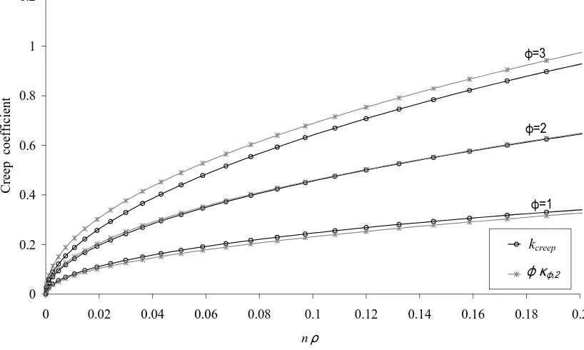
(44) Chapter 2 A simplified method to obtain time-dependent curvatures and deflections of concrete members reinforced with FRP bars. 2.3.3 Comparison with other methods The procedure presented in the CEB Manual on Cracking and Deformations [16], described and illustrated in Ghali and Favre [15], to obtain time-dependent curvatures due to creep is general for SRCS, as is the Eurocode 2 procedure [4]. Moreover it has been proved to be suitable for other reinforcing materials such as FRP [14]. Due to the generality of the method, it seems appropriate to compare it with the method proposed in this work.. Based on [15,17], long-term curvature due to creep can be calculated as: ∆ψ 2,creep (t , t0 ) = ϕ (t , t 0 )κ ϕ ,i ψ i (t 0 ). (19). where the subscript i takes a value of 1 for uncracked transformed sections and 2 for fully cracked transformed sections. κ ϕ is the curvature coefficient related to creep and can be obtained by the following expression:. κ ϕ ,i =. I c + Ac yc ∆y I. (20). Ic is the moment of inertia of the concrete area Ac about an axis through the centroid of the age-adjusted transformed section, yc is the centroid of the Ac, ∆y is the y-coordinate of the centroid of the age-adjusted transformed section, measured downward from the centroid of the transformed section at t0, and I is the moment of inertia of the age-adjusted transformed section. The age-adjusted transformed section is calculated from the age-adjusted elastic modulus of concrete, Ee (t , t0 ) :. Ee (t , t0 ) =. Ec (t0 ) 1 + χ (t , t0 )ϕ (t , t0 ). (21). where χ (t , t0 ) is an ageing coefficient and ϕ (t , t0 ) the creep coefficient at age t. As an alternative to using Eq. (20), the coefficient κ ϕ ,i can be obtained using the charts given by the CEB Design Manual on Cracking and Deformations [17].. -22-.
(45) Chapter 2 A simplified method to obtain time-dependent curvatures and deflections of concrete members reinforced with FRP bars. Comparing Eq. (14) and (19), the proposed coefficient k creep equals the term ϕ (t , t0 )κ ϕ , 2 for a fully cracked member. Both coefficients are compared in Figure 2.3 for three representative values of the creep coefficient, ϕ (t , t0 ) = 1, 2, and 3. A typical value of 0.8 has been taken for the aging coefficient χ (t , t0 ) . Both coefficients show the same trend with small differences, as can be observed in Figure 2.3. 1.2. Creep coefficient. 1. ϕ=3. 0.8 ϕ=2. 0.6. 0.4. ϕ=1 fi.Kfi kcreep. 0.2. ϕkcreep κϕ,2 0 0. 0.02. 0.04. 0.06. 0.08. 0.1. 0.12. 0.14. 0.16. 0.18. 0.2. nρ. Figure 2.3. Comparison of the proposed coefficient kcreep and the coefficient obtained using the CEB [17], ϕ (t , t0 )κ ϕ , 2 .. It is worth noting that, for the same level of accuracy, the proposed simplified coefficient,. k creep , contains implicitly time-dependent parameters, and that its calculus depends only on nρ at the initial time of loading and the creep coefficient φ. The use of the proposed coefficient is therefore an easy method to obtain total curvatures, including creep, from the initial curvature.. -23-.
(46) Chapter 2 A simplified method to obtain time-dependent curvatures and deflections of concrete members reinforced with FRP bars. 2.4 Prediction of total deflections 2.4.1 Simplified method to obtain total deflections In this section a method to obtain total long-term deflection in simply supported beams is presented. The total long-term deflection, δ (t , t0 ) , is given as the sum of instantaneous deflection, δ (t 0 ) , and time-dependent deflection, ∆δ (t , t 0 ) :. δ (t , t0 ) = δ (t0 ) + ∆δ (t , t0 ). (22). where the time-dependent deflection is the sum of creep deflection, ∆δ creep (t , t 0 ) , and shrinkage deflection, ∆δ sh (t , t 0 ) : ∆δ (t , t0 ) = ∆δ creep (t , t0 ) + ∆δ sh (t , t 0 ). (23). For calculation purposes, shrinkage deflection, ∆δ sh (t , t 0 ) , caused by uniform curvature along the span, is considered separately from instantaneous and creep deflections, whose curvature varies along the member as a result of load distribution.. Using Mohr’s second theorem, the deflection for simply supported beams due to uniform shrinkage, ∆δ sh (t , t 0 ) , can be obtained by the following expression: ∆δ sh (t , t0 ) = ∆ψ sh (t , t 0 ). l2 8. (24). where ∆ψ sh (t , t0 ) is the shrinkage curvature calculated using Eq. (4).. Instantaneous and creep deflection can be obtained from double integration of the sectional curvatures. The deflection at the centre of the member strongly depends on the curvature at midlength. In the usual case of parabolic variation of the curvature over the member’s length, the. -24-.
(47) Chapter 2 A simplified method to obtain time-dependent curvatures and deflections of concrete members reinforced with FRP bars. mid-span deflection can be obtained from (Ghali and Favre [17]):. δ (t0 ) =. l2 (ψ e1 + 10ψ centre + ψ e 2 ) 96. (25). where ψe1 and ψe2 are the curvatures at the member’s ends, ψcentre is the curvature at mid-length and l is the member’s length. When the member is simply supported the end curvatures are zero and consequently. δ (t 0 ) =. 5l 2 ψ centre 48. (26). For calculation purposes a linear relationship between deflections and mid-span curvature can therefore be assumed.. Based on the previous considerations, time-dependent deflection due to creep can be approximated by multiplying the instantaneous deflection by the ratio of curvatures, ∆ψ creep (t , t0 ). ψ (t 0 ). , as in:. ∆δ creep (t , t 0 ) = δ (t0 ). ∆ψ creep (t , t 0 ). (27). ψ (t 0 ). Therefore, the total long-term deflection can be given as: . δ (t , t 0 ) = δ (t 0 )1 + . ∆ψ creep (t , t 0 ) l2 + ∆ψ sh (t , t0 ) 8 ψ (t 0 ) . (28). Long-term curvature due to the effect of creep, ∆ψ creep (t , t 0 ) , can be determined using Eq. (1), by interpolating between state 1 (corresponding to the uncracked section) and state 2 (corresponding to the fully cracked section): 2 2 M M ∆ψ creep (t , t 0 ) = 0.5 cr ∆ψ 1,creep (t , t 0 ) + 1 − 0.5 cr ∆ψ 2,creep (t , t 0 ) M M . (29). -25-.
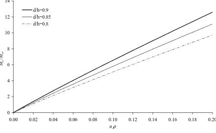
(48) Chapter 2 A simplified method to obtain time-dependent curvatures and deflections of concrete members reinforced with FRP bars. Under serviceability conditions the uncracked part of the beam is expected to make little contribution to the appearance and growth of cracks, and therefore the time-dependent mean curvature due to creep, ∆ψ creep (t , t 0 ) , is assumed to be equal to the time-dependent curvature for a fully cracked section, ∆ψ 2,creep (t , t 0 ) (comparisons are made in the next section):. ∆ψ creep (t , t 0 ) ≈ ∆ψ 2,creep (t , t0 ). (30). Using Eqs. (30) and (14) in Eq. (27), the time-dependent deflection due to creep can be rewritten as: ∆δ creep (t , t 0 ) = δ (t 0 ) k creep. (31). Finally, using Eq. (19) in Eq. (32), the calculation of the total deflection given by Eq. (28) can be approximated by:. (. ). δ (t , t 0 ) = δ (t 0 ) 1 + 0.73ϕ nρ + ∆ψ sh (t , t 0 ). l2 8. (32). 2.4.2 Application range of the simplified method to obtain total deflections In this section, a parametric study is carried out to determine the application range of the simplified method for simply supported beams under serviceability conditions. The applied moment considered corresponds to the service moment Ms, which can be estimated by assuming a recommended maximum bar strain of 2000µε [18] to limit crack widths to acceptable values for FRPRCS members [19,20].. -26-.
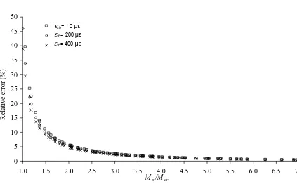
(49) Chapter 2 A simplified method to obtain time-dependent curvatures and deflections of concrete members reinforced with FRP bars. 14 12. d/h=0.9 d/h=0.85 d/h=0.8. Ms /Mcr. 10 8 6 4 2 0 0.00. 0.02. 0.04. 0.06. 0.08. 0.10 nρ. 0.12. 0.14. 0.16. 0.18. 0.20. Figure 2.4. Relationship between Ms/Mcr and nρ for FRP reinforced concrete beams.. On this assumption, the ratio Ms/Mcr can be represented as a function of nρ and the ratio d/h between the effective depth, d, and the height of the section, h, as shown in Figure 2.4.. To examine the error in the long-term deflection prediction when introducing the simplification in Eq. (30), a comparison is made between the direct application of the analytical procedure given by Eq. (28) and the proposed approximate coefficient incorporated in Eq. (32) in terms of the part of the deflection due to creep (first part of the second members in both equations). Usual values of d/h=0.9, φ=2 and Ef ranging between 40 and 120GPa and fc ranging between 20 and 80MPa are considered for the parametric study. Three different. values of shrinkage have been taken into account: 0, 200 and 400µε.. -27-.
(50) Chapter 2 A simplified method to obtain time-dependent curvatures and deflections of concrete members reinforced with FRP bars. 50 esh=0 εsh= 0 µε ε sh= 200 µε esh=200e-4 εsh= 400 µε esh=400e-4. 45 40. Relative error (%). 35 30 25 20 15 10 5 0 1.0. 1.5. 2.0. 2.5. 3.0. 3.5. 4.0 M s /M cr. 4.5. 5.0. 5.5. 6.0. 6.5. 7.0. Figure 2.5. Error made using the proposed method to calculate the total deflection for different levels of concrete shrinkage.. The influence of the ratio Ms/Mcr on the differences obtained is illustrated in Figure 2.5. The relative error decreases with the increase in the ratio Ms/Mcr, due to the fact that the proposed coefficient, k creep , is developed for a fully cracked section, and therefore the highest errors are found when the value of the service moment is closest to the cracking moment. Assuming an error of less than 10% as an acceptable level of accuracy in deflection calculations, the proposed method is seen to be valid for calculating the total deflection for service loads Ms/Mcr greater than 1.5, which in practice includes the majority of cases.. -28-.
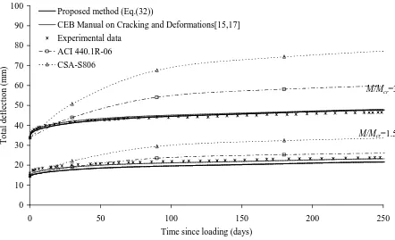
(51) Chapter 2 A simplified method to obtain time-dependent curvatures and deflections of concrete members reinforced with FRP bars. 2.5 Comparison with experimental data The procedure proposed here is compared with the experimental results of long-term deflections of concrete beams reinforced with GFRP bars presented by Hall and Ghali [13]. Two levels of sustained loading were considered, with ratios of M/Mcr equal to 1.5 and 3.0. The beams were 280mm wide, 180mm high and 3500mm long (3200mm span), and were reinforced with 3Ø15mm GFRP bars (ρ=1.29%). The GFRP bars used in these experiments were type 1 C-Bar® with an ultimate tensile strength of 680MPa and a tensile elastic modulus of 42GPa. The values of concrete strength, fc, and the modulus of elasticity of concrete, Ec, as determined from cylinder tests, were 31MPa and 21GPa respectively. With these values the modular ratio is n=2.. The beams were subjected to short-term cyclical loading to represent service conditions before the application of the pair of concentrated loads. The respective load levels were equal to 11.5 and 5.9kN. The temperature in the laboratory remained constant at 23±2ºC and the average relative humidity over the period of the tests was 24%.. The creep coefficient has been calculated with equations given by the CEB-FIB Model Code 1990 [5], while the free shrinkage has been obtained from the average shrinkage of test cylinders [13].. The experimental total mid-span deflections due to the two loading levels, the theoretical deflections calculated using the ACI 440.1R-06 [8] and CSA-S806-02 [11] direct method, the CEB Manual on Cracking and Deformations [15, 17] and the proposed method with the simplified coefficient k creep are plotted and compared in Figure 2.6. The total deflection includes the instantaneous and the time-dependent deflections due to creep and shrinkage. For. -29-.
(52) Chapter 2 A simplified method to obtain time-dependent curvatures and deflections of concrete members reinforced with FRP bars. the ACI 440.1R-06 and CSA-S806-02 [11] direct method, the total deflection is calculated as:. δ (t , t0 ) ACI = δ (t0 )(1 + 0.6ξ ). (34). δ (t , t0 ) CSA = δ (t0 )(1 + S ). (35). where ξ and S are the time-dependent coefficients, with values reported in ACI 318-05 [7] and CSA-S806-02 [11].. 100. Proposed method (Eq.(32)) CEB Manual on Cracking and Deformations[15,17]. 90. Experimental data. Total deflection (mm). 80. ACI 440.1R-06 CSA-S806. 70 60. M/Mcr=3. 50 40. M/Mcr=1.5 30 20 10 0 0. 50. 100. 150. 200. 250. Time since loading (days). Figure 2.6. Comparison of the predicted total mid-span deflection using different methods.. An overestimation of the mid-span deflections for the two beams tested when using ACI 440.1R-06 and CSA-S806-02 is clearly illustrated in Figure 2.6, mainly for the higher load level. However, the proposed method, Eq. (32), and the CEB Manual on Cracking and. -30-.
(53) Chapter 2 A simplified method to obtain time-dependent curvatures and deflections of concrete members reinforced with FRP bars. Deformations [15, 17] give similar predictions for both beams, although the latter requires a higher degree of computation. The quantification of the errors for the respective predictions is shown in Table 2.1.. 2.6 Conclusions A new simplified method for the evaluation of time-dependent deflections of concrete members reinforced with fibre reinforced polymer bars has been proposed. The method has been deduced from general principles based on the Effective Modulus Method and Eurocode 2. From an analytical development of the equations for time-dependent curvature, a new multiplying coefficient to predict time-dependent deflections due to creep of concrete members reinforced with fibre reinforced polymer bars has been proposed. The new coefficient is simple, accurate, and implicitly includes the effects of different materials, mechanical properties, environmental conditions and the age of loading. Based on the aforementioned developments, a simplified method to calculate long-term deflections under serviceability conditions accounting for creep and shrinkage has been presented. A comparison using analytical procedures and the proposed simplification has been made. Good accuracy, with differences of less than 10% for typical cases, has been obtained. Finally, a comparison with experimental results for GFRP reinforced concrete beams reported in the literature has been made, and a good capacity to predict long-term behaviour using the new method has been observed. It has also been shown that using coefficients that do not take into account specific properties can lead to considerable differences in long-term predictions.. -31-.
(54) Chapter 2 A simplified method to obtain time-dependent curvatures and deflections of concrete members reinforced with FRP bars. Pred./Exp. deflections for sustained load: M/Mcr=1.5 Loading time (days). Pred./Exp. deflections for sustained load: M/Mcr=3. CEB Manual. ACI 440.1R-06. CSA-S806. Proposed method. CEB Manual. ACI 440.1R-06. CSA-S806. Proposed method. 30. 0.94. 0.93. 1.08. 0.88. 1.00. 1.04. 1.20. 0.98. 90. 0.97. 1.09. 1.36. 0.90. 1.03. 1.24. 1.55. 1.01. 180. 0.97. 1.09. 1.40. 0.90. 1.03. 1.28. 1.64. 1.02. 250. 0.97. 1.09. 1.41. 0.90. 1.04. 1.29. 1.67. 1.03. Table 2.1. Predicted/Experimental deflections. -32-.
(55) Chapter 2 A simplified method to obtain time-dependent curvatures and deflections of concrete members reinforced with FRP bars. 2.7 Acknowledgements The authors acknowledge the support provided by the Spanish Government (Ministerio de Educación y Ciencia), Project ref. BIA2007-60222. The first author thanks the Ministerio de Educación y Ciencia for Grant BES-2008-005740.. -33-.
(56) Chapter 2 A simplified method to obtain time-dependent curvatures and deflections of concrete members reinforced with FRP bars. 2.8 References. 1. Gilbert R. I, Time effects in concrete Structures. Elsevier, Amsterdam, 1988. 2. Bazant Z.P., Prediction of concrete creep effects using age-adjusted effective modulus method. American Concrete Institute Journal, 69 , 212-217, 1972. 3. Chiorino M., Napoli, P., Mola F.. Koprna M, Structural effects of time-dependent behaviour of concrete. Comité Euro-International du Béton: CEB Design Manual. Bulletin d’Information 136, 1980. 4. CEN 2004, Eurocode 2: Design of Concrete Structures – Part 1-1: General rules and rules for buildings (EN 1992-1-1:2004). Comité Européen de Normalisation, Brussels. 5. CEB- FIP 1990, Model code for concrete structures. Comité Euro-International du Béton. Fédération Internationale de la Précontrainte, Thomas Telford House, London, England, 1990. 6. ACI Committee 435, Control of Deflections in Concrete Structures (ACI 435R-95). American Concrete Institute, Detroit, Michigan, 1995. 7. ACI 318-05, Building Code Requirements for Reinforced Concrete, ACI Committee 318. American Concrete Institute, Detroit, Michigan, 2005. 8. ACI Committee 440, Guide for the Design and Construction of Concrete Reinforced with FRP Bars (ACI 440.1R-06). American Concrete Institute, Farmington Hills, 2006. 9. Brown V. and Bartholomew C., Long-term deflections of GFRP-reinforced concrete beams. First International Conference on Composites in Infrastructure, (ICCI-96), H. Saadatmanesh and M. R. Ehsani, eds., Tucson, Arizona, pp. 389-400, 1996. 10. Brown V., Sustained Load Deflections in GFRP-Reinforced Concrete Beams, Proceedings of the Third Int. Symposium on Non-Metallic (FRP) Reinforcement for Concrete Structures (FRPRCS-3), V. 2, Japan Concrete Institute, Tokyo, Japan, pp. 495-502, 1997.. -34-.
(57) Chapter 2 A simplified method to obtain time-dependent curvatures and deflections of concrete members reinforced with FRP bars. 11. CSA Standard CAN/CSA-S806-02, Design and construction of building components with fibre-reinforced polymers. Canadian Standards Association, Mississauga, Ontario, Canada, 2002. 12. Arockiasamy M., Chidambarama S., Amera A., Shahawy M. Time-dependent deformations of concrete beams reinforced with CFRP bars. Composites Part B: Engineering, 31: 577-592, 2000. 13. Hall T. and Ghali A., Long-term deflection prediction of concrete members reinforced with glass fibre reinforced polymer bars. Canadian Journal of Civil Engineering, 27(5):890– 898, 2000. 14. ACI Committee 209, Manual of concrete practice. Prediction of creep, shrinkage and temperature effects in concrete structures (ACI 209R-92). American Concrete Institute, Detroit, Mich., 1992. 15. Ghali A. and Favre R., Concrete Structures: Stresses and Deformations. Ed. Chapman and Hall, London, 1994. 16. Al-Salloum Y.A., Almusallam T.H. Creep effect on the behavior of concrete beams reinforced with GFRP bars subjected to different environments. Construction and Building Materials, 21: 1510-1519, 2007. 17. Comité Euro-International du Béton (CEB), Manual on Cracking and Deformations. Butlletin d’Information nº 158-E, 1985. 18. Newhook J, Ghali A, Tadros G., Concrete flexural members reinforced with fiber reinforced polymer: design for cracking and deformability. Canadian Journal of Civil Engineering; 29: 125-134, 2002. 19. Bischoff P.H., Reevaluation of deflection prediction for concrete beams reinforced with steel and fiber reinforced polymer bars. Journal of Structural Engineering, 131(5); 752-767, 2005.. -35-.
(58) Chapter 2 A simplified method to obtain time-dependent curvatures and deflections of concrete members reinforced with FRP bars. 20. ISIS Canada, Reinforcing concrete structures with fibre reinforced polymers - Design manual No. 3, Manitoba, Canada: ISIS Canada Corporation, 2001.. -36-.
(59) 3. A rational method to predict long-term deflections of FRP reinforced concrete members. -37-.
(60)
(61) Chapter 3 A rational method to predict long-term deflections of FRP reinforced concrete members. Ll. Torres, C. Miàs, A. Turon, M. Baena, A rational method to predict long-term deflections of FRP reinforced concrete members, Engineering Structures 2012; 40:230-39. doi: 10.1016/j.engstruct.2012.02.021. Summary Due to the low modulus of elasticity of FRP bars, deflection control is often a limiting factor in the design of FRP reinforced concrete (FRP RC) structures. To address long-term deflections due to creep and shrinkage, available codes and guidelines for FRP RC structures, such as ACI 440.1R-06 and CSA-S806-02, propose simplified procedures based on empirical multiplicative coefficients. Although easy to use, these procedures do not account for the influence of changes in material properties or factors affecting creep and shrinkage of concrete. A straightforward method to predict long-term deflections due to creep and shrinkage based on rational multiplicative coefficients deduced from the principles of the Effective Modulus Method (Eurocode 2) is presented. The proposed method, although simple, accounts for main mechanical properties of materials, variations in environmental conditions or other parameters that can affect creep and shrinkage. The method is compared to CEBFIP, ACI 440.1R-06 and CSA-S806-02 proposals. A good agreement between the CEB-FIP and the proposed method is obtained. However, the coefficients proposed by ACI and CSA can lead to considerable differences in long-term predictions with respect to the proposed method depending on the characteristics of the structure.. -39-.
(62)
Figure
+7


Documento similar
Technical report, NCEER-89-0033, National Center for Earthquake Engineering Research, State University of New York at Buffalo.. Brencich, A., y
Model Code (Fib 2013) provides four fatigue design considerations according to level of sophistication: level I approximation is a qualitative verification that no variable action
In most cases, simplified assumptions made in the preliminary considerations (pre- emptive yielding of steel, concrete and steel failure in unconfined and confined
The tests revealed that the proposed method of thermal-mechanical treatment of concrete debris from the demolition of structural elements of a 30-year-old industrial hall allows
Different configurations of hybrid model combining wavelet analysis and artificial neural network for time series forecasting of monthly precipitation have been developed and
With respect to datasets, existing datasets that met our analysis of requirements have been selected, which have been completed with the creation of two new datasets, completing a
Different methods for removing interference by humic substances in the analysis of polar pollutants have been compared in the analysis of environmental water by solid-phase
While most of the studies have been focused on the stationary regime [31–36], in this chapter I present the analysis of the time dependent dynamics of mesoscopic supercon- ductors.
