Campus Monterrey
Monterrey, Nuevo León a
Lic. Arturo Azuara Flores:
Director de Asesoría Legal del Sistema
Por medio de la presente hago constar que soy autor y titular de la obra
", en los sucesivo LA OBRA, en virtud de lo cual autorizo a el Instituto
Tecnológico y de Estudios Superiores de Monterrey (EL INSTITUTO) para que
efectúe la divulgación, publicación, comunicación pública, distribución y
reproducción, así como la digitalización de la misma, con fines académicos o
propios al objeto de EL INSTITUTO.
El Instituto se compromete a respetar en todo momento mi autoría y a
otorgarme el crédito correspondiente en todas las actividades mencionadas
anteriormente de la obra.
De la misma manera, desligo de toda responsabilidad a EL INSTITUTO
por cualquier violación a los derechos de autor y propiedad intelectual que
cometa el suscrito frente a terceros.
In the Task-Driven Generation of Preventive Sensing Plans for
Execution of Robotic Assemblies
Title In the Task-Driven Generation of Preventive Sensing Plans for Execution of Robotic Assemblies
Authors Conant Pablos, Santiago E.
Affiliation ITESM
depends on the correct execution of the sequence of assembly steps established in a plan. In turn, the correct execution of these steps depend on the conformance to a series of preconditions and postconditions on the states of the assembly elements and in the consistent, repeatable, and precise actions of the assembler (for instance, a robotic arm). Unfortunately, the ubiquitous and inherent real-life uncertainty and variation in the work-cell, in the assembly robot calibration, and in the robot actions, could produce errors and deviations during the execution of the plan. This dissertation investigates several issues related to the use of geometric information about the models of component objects of assemblies and the process of contact formation among such objects for tackling the automatic planning of sensing strategies. The studies and experiments conducted during this research have led to the development of novel methods for enabling robots to detect critical errors and deviations from a nominal assembly plan during its
execution. The errors are detected before they cause failure of assembly operations, when the objects that will cause a problem are manipulated. Having control over these objects, commanded adjustment actions are expected to correct the errors. First, a new approach is proposed for determining which assembly tasks require using vision and force feedback data to verify their preconditions and the preconditions of future tasks that would be affected by lack of precision in the execution of those tasks. For this, a method is proposed for systematically assign force compliance skills for monitoring and controlling the execution of tasks that involve contacts between the object manipulated by the robot arm in the task and the objects that conform its direct environmental configuration. Also, a strategy is developed to deduce visual sensing requirements for the manipulated object of the current task and the objects that conform its environment configuration. This strategy includes a geometric reasoning mechanism that propagates alignment constraints in a form of a dependency graph. Such graph codes the complete set of critical
alignment constraints, and then expresses the visionand force sensing requirements for the analyzed assembly plan. Recognizing the importance of having a correct
represents the heart of this dissertation work because it provides the basis for the rest of the contributions and work. The approach was extensively tested demonstrating its correct execution in all the test cases. Next, knowing which are the tasks that require preventive sensing operations, a sensor planning approach is proposed to determine an ordering of potential viewpoints to position the camera that will be used to implement the feedback operations. The approach does not consider kinematic constraints in the active camera mechanism. The
viewpoints are ordered depending on a measure computed from the intersection of two regions describing the
tolerance of tasks to error and the expected uncertainty from iii an object localization tool. A method has been posed to analytically deduce the descriptions of inequalities that implicitly describe a region of tolerated error. Also, an algorithm that implements an empirical method to
determine the form and orientation of six-dimensional ellipsoids is proposed to model and quantify the
uncertainty of the localization tool. It was experimentally shown that the goodness measure is an adequate criterion for ordering the viewpoints because agrees with the
resulting success ratio of real-life task execution after using the visual information to adjust the configuration of the manipulated objects. Furthermore, an active vision
mechanism is also developed and tested to perform visual verification tasks. This mechanism allows the camera move around the assembly scene to recollect visual information. The active camera was also used during the
experimentation phase. Finally, a method is proposed to construct a complete visual strategy for an assembly plan. This method decides the specific sequence of viewpoints to be used for localizing the objects that were specified by the visual sensing analyzer. The method transforms the
problem of deciding a sequence of camera motions into a multi-objective optimization problem that is solved in two phases: a local phase that reduces the original set of potential viewpoints to small sets of viewpoints with the best predicted success probability values of the
kinematically feasible viewpoints for the active camera; and a global phase that decides a single viewpoint for each object in a task and then stitch them together to form the visual sensing strategy for the assembly plan.
Discipline Ingeniería y Ciencias Aplicadas / Engineering & Applied Sciences
.dc.contributor.adv isor???
???pdf.cover.sheet .thesis.degree.disci pline???
Electronics, Computing, Information and Communications
???pdf.cover.sheet .thesis.degree.prog ram???
Campus Monterrey
Rights Open Access
Downloaded 18-Jan-2017 08:05:51
On the Task-Driven Generation of Preventive Sensing
Plans for Execution of Robotic Assemblies
SANTIAGO ENRIQUE CONANT PABLOS
Ph.D. DISSERTATION
INSTITUTO TECNOL ´
OGICO Y DE ESTUDIOS
SUPERIORES DE MONTERREY
On the Task-Driven Generation of Preventive Sensing
Plans for Execution of Robotic Assemblies
A Dissertation Presented by
Santiago Enrique Conant Pablos
Submitted in partial fulfillment of
the requirements for the degree of
Doctor of Phylosophy
in the field of
Artificial Intelligence
Thesis Committee:
Katsushi Ikeuchi, The University of Tokyo Horacio Martinez Alfaro, ITESM Campus Monterrey Jos´e Manuel Sanchez Garc´ıa, ITESM Campus Monterrey
Noel Le´on Rovira, ITESM Campus Monterrey Olivia Maricela Barr´on Cano, ITESM Campus Monterrey
Center for Intelligent Systems
Instituto Tecnol´ogico y de Estudios Superiores de Monterrey
Campus Monterrey
Declaration
I hereby declare that I composed this dissertation entirely myself and that it describes my own research.
Santiago Enrique Conant Pablos Monterrey, N.L., M´exico
Instituto Tecnol´ogico y de Estudios Superiores de Monterrey
Campus Monterrey
Graduate Program in
Electronics, Computing, Information and Communications
The committee members hereby recommend the dissertation presented by Santiago Enrique Conant Pablos to be accepted as a partial fulfillment of requirements to be admitted to the Degree of Doctor of Philosophy in Artificial Intelligence.
Committee members:
Dr. Katsushi Ikeuchi Advisor
Dr. Horacio Mart´ınez Alfaro Advisor
Dr. Jos´e Manuel Sanchez Garc´ıa
Dr. Noel Le´on Rovira
Dr. Olivia Maricela Barr´on Cano
Dr. David A. Garza Salazar. Director of Graduate Program in
Abstract
It is well known that success during robotic assemblies depends on the correct execution of the sequence of assembly steps established in a plan. In turn, the correct execution of these steps depend on the conformance to a series of preconditions and postconditions on the states of the assembly elements and in the consistent, repeatable, and precise actions of the assembler (for instance, a robotic arm). Unfortunately, the ubiquitous and inherent real-life uncertainty and variation in the work-cell, in the assembly robot calibration, and in the robot actions, could produce errors and deviations during the execution of the plan.
This dissertation investigates several issues related to the use of geometric information about the models of component objects of assemblies and the process of contact forma-tion among such objects for tackling the automatic planning of sensing strategies. The studies and experiments conducted during this research have led to the development of novel methods for enabling robots to detect critical errors and deviations from a nominal assembly plan during its execution. The errors are detected before they cause failure of assembly operations, when the objects that will cause a problem are manipulated. Hav-ing control over these objects, commanded adjustment actions are expected to correct the errors.
First, a new approach is proposed for determining which assembly tasks require using vision and force feedback data to verify their preconditions and the preconditions of future tasks that would be affected by lack of precision in the execution of those tasks. For this, a method is proposed for systematically assign force compliance skills for monitoring and controlling the execution of tasks that involve contacts between the object manipulated by the robot arm in the task and the objects that conform its direct environmental configuration. Also, a strategy is developed to deduce visual sensing requirements for the manipulated object of the current task and the objects that conform its environment configuration. This strategy includes a geometric reasoning mechanism that propagates alignment constraints in a form of a dependency graph. Such graph codes the complete set of critical alignment constraints, and then expresses the visionand force sensing requirements for the analyzed assembly plan. Recognizing the importance of having a correct environment configuration to succeed in the execution of a task that involve multiple objects, the propagation of critical dependencies allow to anticipate potential problems that could irremediably affect the successful execution of subsequent assembly operations. This propagation scheme represents the heart of this dissertation work because it provides the basis for the rest of the contributions and work. The approach was extensively tested demonstrating its correct execution in all the test cases.
Next, knowing which are the tasks that require preventive sensing operations, a sen-sor planning approach is proposed to determine an ordering of potential viewpoints to position the camera that will be used to implement the feedback operations. The ap-proach does not consider kinematic constraints in the active camera mechanism. The viewpoints are ordered depending on a measure computed from the intersection of two regions describing the tolerance of tasks to error and the expected uncertainty from
scriptions of inequalities that implicitly describe a region of tolerated error. Also, an algorithm that implements an empirical method to determine the form and orientation of six-dimensional ellipsoids is proposed to model and quantify the uncertainty of the localization tool. It was experimentally shown that the goodness measure is an adequate criterion for ordering the viewpoints because agrees with the resulting success ratio of real-life task execution after using the visual information to adjust the configuration of the manipulated objects.
Furthermore, an active vision mechanism is also developed and tested to perform visual verification tasks. This mechanism allows the camera move around the assembly scene to recollect visual information. The active camera was also used during the experimen-tation phase.
Finally, a method is proposed to construct a complete visual strategy for an assembly plan. This method decides the specific sequence of viewpoints to be used for localizing the objects that were specified by the visual sensing analyzer. The method transforms the problem of deciding a sequence of camera motions into a multi-objective optimiza-tion problem that is solved in two phases: a local phase that reduces the original set of potential viewpoints to small sets of viewpoints with the best predicted success proba-bility values of the kinematically feasible viewpoints for the active camera; and a global phase that decides a single viewpoint for each object in a task and then stitch them together to form the visual sensing strategy for the assembly plan.
Dedication
To my wife Jaqueline.
To my kids Santiago, Gerardo, and Jackeline.
To my parents Santiago and Odila.
Thanks for all your unconditional confidence, support, patience, and encouragement. You were my main motivation for pushing through this work.
Acknowledgements
I would first like to express my gratitude to my advisor Dr. Katsushi Ikeuchi for his uncondi-tional support, advise and encouragement during the course of this research. Discussions with him, his insights and vast experience greatly helped me to find the right directions. I thank him for giving me the opportunity to explore many ideas and for having an open door and open mind whenever I needed it. I was fortunate to be accepted by him as a Visiting Scholar at Carnegie Mellon University (CMU) and as a Visiting Research Associate at The University of Tokyo (UT). His help and support during my internships were invaluable. Sensei, thank you very much!
I am also indebted to my local supervisor Dr. Horacio Mart´ınez for his advice, encouragement and guidance. I also thank my dissertation committee members Dr. Noel Le´on, Dr. Jos´e M. S´anchez, and Dr. Olivia M. Barr´on for their careful reading of this dissertation and their valuable feedback regarding this manuscript.
I thank to Dr. Francisco Cant´u, Dr. Rogelio Soto, and Dr. Fernando Jaimes for their support, patience, and constant stimulation to continue and finish my doctoral studies, while a student and member of the current Center for Intelligent Systems and former Center for Artificial Intelligence.
I recognize the financial support of ITESM and CONACyT, without it, it would have been impossible to realize this dream. Special thanks to the Robotics Institute at CMU and the In-stitute of Industrial Sciences at UT for allowing me to use its excellent computational resources and facilities to develop this research.
I would like to express my gratitude to my fellows and friends at CMU: thanks to Antonio Diaz, Octavio Juarez, George V. Paul, Yoichi Sato, Imari Sato, Hiroshi Kimura, Kohtaro Ohba, Mark Wheeler, Prem Janardhan, Harry Shum, and Yunde Yiar. Thanks also to my fellows and friends at UT: Masataka Kagesawa, Yoichi Sato, Imari Sato, Ko Nishino, Kentaro Kawa-mura, Keiko Motoki, Tomotaka Saito, Tomoyuki Horiuchi, Hajime Ohno, Hirohisa Tominaga, Koichi Ogawara, Yoshiko Matsuura and Jun Takamatsu. Special thanks for his friendship and attentions to Hiroshi Kimura. My internships would have been much more difficult without them. I cherished their company and friendship.
A very special thank to my “Gran Compadre” Hugo Terashima who was always there for me. His encouragement, advise, and unconditional support helped me to persevere and finish this work. He was always interested and cheering me up. His help has been priceless.
I would also like to express my gratitude to my fellows and friends at the CSI: Olivia Barr´on, Manuel Valenzuela, Leonardo Garrido, Eduardo Uresti, Ram´on Brena, Jos´e Luis Aguirre, Nora Aguirre, Doris Garc´ıa, Arturo Galv´an, Carlos Cant and Leticia Rodr´ıguez. Their friendship during all these years has been very important to me. I also like to thank my fellow and friend Jos´e Luis Gordillo for introducing me to the scientific world, advising me, and putting me in the right research path.
Last but certainly not least, my biggest gratitude and appreciation goes to all members of my family: my wife, my kids, my parents, my siblings, my nephews and nieces, and my parents and siblings in law, for their love, patience, confidence, support, and help for these many years and for the years to come.
Contents
Committee Declaration 3
Declaration 5
Abstract iv
List of Figures xix
List of Tables xx
1 Introduction 1
1.1 Motivation . . . 1
1.2 Problem Statement and Context . . . 2
1.3 Research Questions . . . 4
1.4 Solution Overview . . . 5
1.4.1 Sensing Analysis . . . 5
1.4.2 Sensor Planning . . . 8
1.4.3 Active Camera Design . . . 9
1.4.4 Visual Sensing Planning . . . 10
1.5 Main Contributions . . . 10
1.6 Literature Review and Background . . . 11
1.6.1 Assembly Execution using Vision and Force Feedback Data . . . . 11
1.6.2 Contact-State Analysis and Identification . . . 13
1.6.3 Visual Sensor Placement and Sensing Strategies . . . 14
2 Sensing Analysis for Robotic Assembly 19
2.1 Analysis of Contact States Formation . . . 20
2.1.1 Definitions . . . 20
2.1.2 Analyzing and Representing Contact States . . . 22
2.1.3 Analyzing and Representing Assembly Tasks as Procedure Graphs 26 2.1.4 Assembly Skill Primitives . . . 28
2.1.5 Identifying Contact States . . . 30
2.2 Determining the Required Sensing for Robotic Assembly . . . 32
2.3 Force and Torque Sensing . . . 33
2.3.1 Using Force Compliance . . . 34
2.3.2 Force Compliance Skills . . . 35
2.4 Visual Sensing . . . 38
2.4.1 Determining Assembly Relations by Vision . . . 38
2.4.2 Preventive Vision for a Manipulated Object . . . 40
3 Preventive Vision for Robotic Assembly 47 3.1 Preventive Vision for Environmental Objects . . . 47
3.1.1 Visual Sensing for Insertion Condition . . . 48
3.1.2 Visual Sensing for Contact Prescription . . . 50
3.2 Insert and Contact Dependency Graph . . . 52
3.2.1 Elements of an Insert And Contact Dependency Graph . . . 52
3.2.2 Propagation of Alignment Constraints . . . 58
3.3 Dependency Relations and Their Propagation . . . 61
3.3.1 A Reference Frame to Describe Dependency Relations . . . 61
3.3.2 Obtaining Reference Vectors . . . 62
3.3.3 Additional Propagation by Configuration Conditioning . . . 65
3.3.4 Rotational Considerations . . . 67
3.4 Sensing Analysis for Robotic Assembly: Putting It Together . . . 71
3.5 Experiments and Discussion . . . 73
3.5.1 Experimental Case 1 . . . 73
3.5.2 Experimental Case 2 . . . 78
3.5.3 Experimental Case 3 . . . 83
4 Sensor Planning for Visual Verification 91
4.1 Assembly Uncertainty . . . 93
4.1.1 Uncertainty in Robotic Assembly . . . 94
4.1.2 Sources of Uncertainty and Errors . . . 94
4.2 Evaluation of Visual Sensing Strategies . . . 97
4.2.1 Evaluating Viewpoints . . . 98
4.2.2 Quantifying success . . . 99
4.3 Modeling and Quantifying Task Tolerance To Errors . . . 102
4.3.1 Quantifying Error Tolerance in Critical Dimensions . . . 103
4.3.2 Deducing Inequality Points and Constraining Planes for Insertion 105
4.3.3 Deducing Inequality Points and Constraining Planes for Environ-mental Objects . . . 109
4.3.4 Obtaining Task Tolerance Inequalities . . . 110
4.4 Modeling and Quantifying Sensing Uncertainty . . . 125
4.4.1 Experimental Testbed . . . 125
4.4.2 Modeling and Quantifying Sensing Uncertainty . . . 127
4.5 Predicted Success Probability . . . 135
4.5.1 Peg-in-Hole Experiments . . . 135
5 Active Placement and Sensing Planning 145
5.1 The Active Camera Mechanism . . . 145
5.2 Active Camera Calibration . . . 146
5.2.1 Calibration of the Fixed Camera Model . . . 148
5.2.2 Calibration of the Camera Manipulator . . . 150
5.2.3 Calibration of Pan and Tilt Rotation Axes . . . 153
5.3 Active Camera Adjustment . . . 165
5.3.1 Correcting the Camera’s Attitude . . . 165
5.3.2 Correcting the Viewpoint Position . . . 170
5.4 Preventive Visual Strategies for Robotic Assemblies . . . 171
5.4.1 First Stage: Selecting Viewpoints for Assembly Steps . . . 173
5.4.2 Second Stage: Constructing A Global Strategy . . . 177
6 Conclusions 181
6.1 Contributions . . . 181
6.1.1 Automatic Deduction of Skills . . . 182
6.1.2 Representation of Sensing Requirements . . . 183
6.1.3 Propagation Scheme of Critical Dependencies . . . 183
6.1.4 Analytical Description of Regions of Tolerated Error . . . 184
6.1.5 Modeling and Quantification of Sensing Uncertainty . . . 185
6.1.6 Ordering of Camera’s Viewpoints . . . 185
6.1.7 An Active Camera Mechanism . . . 186
6.1.8 Computation of Preventive Vision Strategies . . . 187
6.2 Future Directions . . . 187
6.2.1 Sensing Planning . . . 187
6.2.2 Sensor Planning . . . 188
6.2.3 Sensing Execution . . . 188
Bibliography 191
A Representation of Rigid Transformations 201
A.1 2D Rigid Transformations . . . 201
A.2 3D Rigid Transformations . . . 201
B Assembly Planning Terminology 203
C The 2DTM Object Localization Tool 207
C.1 3D-2D Object Representation . . . 208
C.2 3D-2D Object Localization . . . 209
C.2.1 Edgel Visibility . . . 210
C.2.2 Model-to-Image Edgel Correspondence . . . 212
C.2.3 Pose Optimization . . . 213
List of Figures
1.1 Overview of Solution Strategy. . . 6
2.1 Gaussian sphere representation of a single contact constraint. . . 24
2.2 Contact states taxonomies for translation. . . 25
2.3 Procedure trees used in APO. . . 27
2.4 Taxonomy of DOF transitions. . . 28
2.5 Procedure graphs. . . 28
2.6 Automaton representing the effect of an assembly step on a manipulated object’s DOF. . . 29
2.7 Assembly skill primitives. . . 30
2.8 Force compliance skills. . . 36
2.9 Implementing a make-contact assembly skill primitive through force com-pliance skills . . . 37
2.10 Implementing insert assembly skill primitives through force compliance skills . . . 38
2.11 Task stability due to the partial assembly configuration. . . 41
2.12 Tasks requiring visual sensing. . . 43
2.13 Critical dimensions for the insert assembly skill primitive. . . 44
2.14 Transition of assembly relations that include critical dimensions for rota-tion in 2-D space . . . 44
2.15 Transitions of assembly relations that include critical dimensions for ro-tation in 3-D space . . . 45
3.1 Configurations for insertion. . . 49
3.2 Vision to verify indirect insert dependencies. . . 50
3.4 Types of arcs used to record alignment constraints that describe relations among objects in 2-D space. . . 54
3.5 Types of arcs used to record alignment constraints that describe relations among objects in 3-D space. . . 55
3.6 Types of contact relations between polyhedral objects. . . 56
3.7 Constraining effects of face contact relations. . . 57
3.8 Type of alignment constraints resulting from propagation. . . 59
3.9 Obtaining reference vectors to deduce a reference frame for the description of critical dimensions. . . 64
3.10 Contacts requiring additional propagation of alignment constraints. . . . 66
3.11 Obtaining critical rotation axes. . . 69
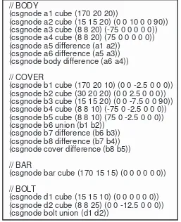
3.12 VANTAGE model of parts for test case 1 . . . 74
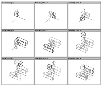
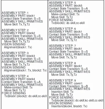
3.13 Nominal assembly plan for test case 1 . . . 74
3.14 Sequence of assembly steps for test case 1 . . . 75
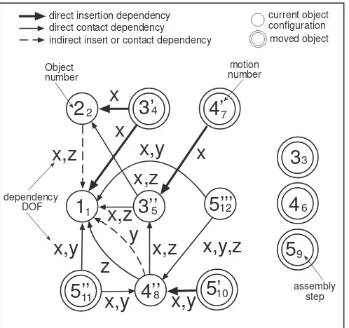
3.15 ICdg for test case 1 . . . 76
3.16 assembly plan with sensing operations for test case 1 . . . 78
3.17 VANTAGE models of parts for test case 2 . . . 79
3.18 Nominal assembly plan for test case 2 . . . 79
3.19 Sequence of assembly steps for test case 2 . . . 80
3.20 ICdg for test case 2 . . . 81
3.21 Assembly plan with sensing operations for test case 2 . . . 82
3.22 VANTAGE models of parts for test case 3 . . . 83
3.23 Nominal assembly plan for test case 3 . . . 84
3.24 Sequence of assembly steps for test case 3 . . . 85
3.25 ICdg for test case 3 . . . 87
3.26 Assembly plan with sensing operations for test case 3 . . . 88
4.1 Spherical representation used to model the sensor configurations. . . 92
4.2 Precision of object localization tool for position estimation of a peg object. 97
4.3 Distribution of viewpoints. . . 98
4.4 Predicted Success Probability. . . 100
4.5 Effect of rotation errors in constraining relations. . . 105
4.6 Insertion plane in an insertion operation. . . 106
4.7 Intersection region computation for contacting planar surfaces. . . 107
4.8 Inequality points and constraining planes for an insertion task. . . 108
4.9 Indirect effect of violating a propagated alignment constraint. . . 109
4.10 Elements of Task Tolerance Inequalities. . . 110
4.11 A multiple contact configuration where the dependent object is com-pletely unconstrained. . . 112
4.12 Examples of Task Tolerance Regions for two initially unconstrained en-vironmental objects in a make-contact operation. . . 114
4.13 A multiple contact configuration where the dependent object critical con-figuration is completely fixed by a third environmental object. . . 116
4.14 A multiple contact configuration where the dependent object is in a con-tact relation which is orthogonal to the constraining plane. . . 116
4.15 A multiple contact configuration where the dependent object is in a con-tact relation which is inclined to the constraining plane. . . 117
4.16 A multiple contact configuration where the dependent object is com-pletely unconstrained. . . 119
4.17 Examples of constraint inequalities for an initially unconstrained envi-ronmental object in a make-contact operation. . . 120
4.18 A multiple contact configuration where the dependent object critical con-figuration is completely fixed by a third environmental object. . . 122
4.19 A multiple contact configuration where the dependent object is in a con-tact relation which is inclined to the constraining plane. . . 122
4.20 A multiple contact configuration where the dependent object is in a con-tact relation which is orthogonal to the constraining plane. . . 124
4.21 Precision in the localization of peg and hole objects. . . 127
4.22 Real experimental objects. . . 128
4.23 Precision of 2DTM with respect to the axis parallel to the direction of multiple lines. . . 129
4.24 Precision of 2DTM with respect to the axis orthogonal to the direction of multiple lines. . . 130
among lines changes. . . 131
4.26 Precision of 2DTM when the initial error is duplicated. . . 132
4.27 Uncertainty ellipsoids. . . 133
4.28 FAROT DD Fujitsu arm and its base coordinate system. . . 137
4.29 Success Ratio from Real Experiments. . . 141
4.30 P sp from Real Experiments by using 2.5 Standard Deviations. . . 141
4.31 Success Ratio from Experiments with Synthetic Images. . . 142
4.32 P sp from Experiments with Synthetic Images by using 2.5 Standard De-viations. . . 143
4.33 Predicted Success Probability for Peg-in-Hole Task. . . 144
5.1 The Camera’s Positioning Mechanism. . . 146
5.2 Positioning Process. . . 147
5.3 Active camera components. . . 148
5.4 Tsai’s fixed perspective-projection camera model with radial lens distortion.149
5.5 Coordinate Frames Relations. . . 151
5.6 Configuration of pan and tilt rotational axes under the assumption of full alignment. . . 154
5.7 Motion of the optical center of the camera in world coordinates under panning and tilting motion. . . 155
5.8 Configuration of pan and tilt rotational axes when they do not pass through the optical center of the camera. . . 156
5.9 Configuration of pan and tilt rotational axes when they do not pass through the optical center of the camera and are not aligned with the axes of the camera’s coordinate system. . . 160
5.10 Precision after Calibration of Pan and Tilt Rotation Axes when Camera is Panned. . . 163
5.11 Precision after Calibration of Pan and Tilt Rotation Axes when Camera is Tilted. . . 164
5.12 Elements for determining a viewpoints sequence to observe two objects. . 173
5.13 Selection of sets of viewpoints for each assembly step. . . 174
C.1 Mapping of viewing directions to a latitudinal/longitudinal tessellated hemisphere by stereographic projection. . . 212
C.2 3D error computation for a edgel correspondence. . . 214
Chapter 1
Introduction
1.1
Motivation
The interest in systems that automatically generate robot programs for assembly tasks is growing due to the wider use of industrial robots in assembly applications [69]. This interest has been motivated by the desire to reduce costs in small batch manufacturing applications and to reduce time to reach rapidly changing markets.
The successful execution of assembly plans by robots is of fundamental importance in modern manufacturing industries. In most of the cases, such success is reached by surrounding the assembly cell by hard automation devices that guarantee the conditions assumed by the plan. This devices increase the cost and reduce the flexibility of the system.
No matter how many factors were taken into account during the automatic assembly planning process, the failure of its blind execution and otherwise, the cost of the hard engineering required to ensure its success, remains one of the most motivational facts for the development of new approaches and techniques to cope with real life uncertainty and errors during assembly plan execution. The roll of the hard engineering is precisely to reduce or eliminate the uncertainty and errors that, otherwise, would modify the state of the system in an unexpected way and produce failure.
In an ideal world, uncertainty – a level of variability in an action’s outcome or mea-surement result – can be ignored. If uncertainty is absent, the assembly planner can define tasks that guarantee success and its verification during execution is not required. Unfortunately, ideal worlds only exist in simulated environments, where most of the task planners do their job. Robot plan execution outside the simulated environment had to deal with real world uncertainty. Uncertainty transform real plan execution in an error-prone task.
2 CHAPTER 1. INTRODUCTION
Commonly, to reduce the requirements of hard automation devices and still succeed in making a robot execute an specific assembly plan, the sequence of operations gener-ated by the task planner (whether human, computational, or some combination) has to include an intermingled sequence of assembly-action/sensory-feedback/adjusting-action commands, so that the assembly execution advance could be monitored and deviations from the plan (if any) could be prevented or corrected [6].
There are several proposals for coping with uncertainty using sensory information during assembly planning and plan execution [64]. Every one working under a set of specific assumptions and restrictions. From them it can be concluded that the development of domain-independent planners is currently beyond the scope of our technology and that task-oriented domain knowledge is required to generate successful plans.
1.2
Problem Statement and Context
Fully automated assembly task planning suffers of combinatorial explosion which makes it inappropriate in most realistic situations. Kavraki et al. [54] proved, that the prob-lem of automatically generating assembly sequences is NP-complete even in the two-dimensional case. Adding uncertainty and the requirement of including sensory-feedback operations does not make it better. To deal with this problem, several clues and con-straints have to be inserted into the system to reduce its complexity at a manageable size. Natural constraints come from geometry and physics of a domain-specific knowledge; artificial constraints are simplifying assumptions that together with heuristics work as focusing hints to reduced sets of partial or full potential solutions.
An assembly plan describes a sequence of steps that have to be performed by a robot in order to assemble a group of parts. In this dissertation these parts are modeled as polyhedral objects that are manipulated by a robot arm, also referred as manipulator, one at the time.
The manipulation process of an assembly part by the robot is composed, basically, by a series of transit, grasping, transfer and ungrasping operations. A transit operation is an assembly step where the manipulator moves without carrying an object. A grasping operation is an assembly step where the manipulator takes control over an object by grabbing it with is end-effector (gripper orhand). This object is subsequently known as
themanipulated object. A transfer operation is an assembly step where the manipulator
of sensing data will depend on the category in which an object’s motion falls.
The configurations of the parts – their position and orientation – specified in a nominal
assembly plan are expected to be reached while performing transfer operations. During some of these assembly steps, the manipulated object enters in contact – a state or condition of touching or of being in immediate proximity – with some stationary objects. These objects are subsequently known asenvironmental objects. It is also expected that the fixed condition and pose of the environmental objects is maintained during and after the execution of such steps. A convenient way to take into account the robot actions during transit operations is considering its hand and fingers as mating parts that generate temporalcontact states – configuration of contacts between the assembly components – when grasping new objects. In this way, the robot’s gripper can be considered as the manipulated object and the object to be grabbed as an environmental object in an insertion operation.
It is well known that success during robotic assemblies depends on the correct execution of the sequence of assembly steps established in a plan. In turn, the correct execution of these steps depend on the conformance to a series of preconditions and postconditions on the states of the assembly elements and in the consistent, repeatable, and precise actions of the assembler (for instance, a robotic arm). Unfortunately, the ubiquitous and inherent real-life uncertainty and variation in the work-cell, in the assembly robot calibration, and in the robot actions, could produce errors and deviations during the execution of the plan. In those cases, either the planned configuration of the manipulated object is not accurately achieved or the configurations of some environmental objects are modified by the physical interaction with the manipulated object, during the execution of an assembly step.
The roll of hard automation devices, such as fixtures, automatic feeders, re-orienting devices and ad-hoc grippers and tools, is, precisely, to reduce the uncertainty with respect to the location and configuration of the assembly elements. In this way, the conditions expected in an assembly plan are assured. Planning, constructing and using such devices is a very interesting and complex problem by itself. Furthermore, its presence and use increase the work-cell cost and resistance to change, then reducing the work-cell’s flexibility. However, it is not always possible nor convenient to eliminate them from a work-cell, because uncertainty would introduce the possibility of errors and deviations from absolute expected conditions.
4 CHAPTER 1. INTRODUCTION
pay for the earned flexibility is a reduction on the reliability of the plan execution.
Strictly speaking, uncertainty affects all the tasks, however, every assembly operation has a capacity to tolerate certain amount of error: objects offer some resistance to be moved, insertion slot configurations include some clearance for insertion, the robot arm allows some passive compliance, etc. Then, not necessarily all assembly operations require of sensing verification.
This dissertation presents an approach to the automatic planning of sensing strategies to cope with potential problems to be caused by real-life uncertainty and errors during assembly task execution. The approach assumes the use of force feedback operations to perform force compliance tasks, determine visual sensing requirements, and implement visual sensing strategies to detect and prevent (or at least reduce) the possibility of failure during the execution of the assembly operations. Several computer programs that implement the introduced methods were developed. The problem starts with a
nominal assembly plan, i.e. a sequence of assembly tasks that would execute successfully
in the absence of uncertainty, and propose a visual sensing strategy that maximize the possibilities of success of the tasks by characterizing, modeling, and minimizing the uncertainty from different physical sources with respect to the task tolerances.
1.3
Research Questions
The main motivation for this dissertation was the discovery that assembly is not a trivial endeavor for a robot. The assembly plan and assembly execution by a robot requires of a trade-off between the reliability and the flexibility of the solutions. Then, it is worth a try finding new approaches to avoid failure or at least increase the possibilities of success in the robotic execution of an assembly operation while reducing the requirements of hard automation.
The questions which motivated and guided the research presented in this dissertation are the following:
• Why does a robot fail to execute an assembly plan?
• What is the roll of hard engineering devices such as fixtures in the successful execution of assembly plans?
• Is it possible to eliminate some of these devices by using sensing?
• What are the consequences of eliminating some of these devices?
• What are the most difficult assembly tasks for a robot?
• Is it enough with using sensing in these tasks?
• Which other tasks require of sensing?
• Which type of sensory information is needed for a task?
• What sensory information is needed for task’s sensing?
• Which are the assembly elements that contain such information?
• When is it recommended to use vision?
• What visual information is required?
• How is this information obtained?
• What is the best visual sensing strategy to get such information?
• How can the selected strategy be implemented?
• What kind of vision sensor to use?
• How is this sensor controlled during sensing?
• What to do in the case of detecting an error or deviation from the assembly plan?
1.4
Solution Overview
This dissertation presents an innovative approach to the automatic planning of sensing strategies to help in the successful execution of assembly plans by robots. Figure 1.1 depicts a graph that describes the solution strategy followed during the development of this research. The contributions of this work were constructed around four main elements: a sensing analyzer, a sensor planner, a design of an active vision mechanism, and a sensing planner. The figure also shows the chapters of this document where each of the elements are described.
1.4.1
Sensing Analysis
6 CHAPTER 1. INTRODUCTION Nominal Assembly Plan Preventive Sensing Strategy CAD Models ICdg Viewpoint Order Active Camera Model
Sensing Planning for Robotic Assemblies
Sensing Planner Sensor Planner Sensing Analyzer Active Camera Design Camera
Model RobotModel
Sensor Uncertainty
Model
Chs. 2 & 3
Ch. 4 Ch. 5
[image:36.612.122.442.92.365.2]Ch. 5
Figure 1.1: Overview of Solution Strategy.
produces as output a sensing requirements specification. The most important output is a coded form of the sensing requirements in the Insertion and Contact dependency graph (ICdg), which is detailed in Chapter 3.
The criteria used to decide which tasks require of sensing operations is that of reaching specific contact-state relations among mating objects. It is realized that the nature of mating operations is very important, specially those which resulted of what is known
as fine-motion planning (planning of jam-free sliding motions to achieve a goal
config-uration of a set of spatial relationships between assembly parts [16]), e.g. peg-and-hole operations. These tasks have a low-tolerance to errors during their execution and are considered the most difficult tasks for a robot. Such assembly operations usually require of adaptive behaviors in accordance with a planned maneuvering strategy.
To have success in a fine-motion operation a series of preconditions have to be met. To fulfill such preconditions, additional tasks could require of using sensing feedback oper-ations, e.g. sensing tasks are recommended to ensure that expected insertion configura-tions are obtained for future insertion operaconfigura-tions. Then the recognition of fine-motion tasks ,during the sensing analysis, fires up a backward reasoning process to recognize new operations where sensing verification is needed.
this dissertation, the sensing strategies assumes the use of force and vision sensors. The use of force feedback data is recommended during the task execution to detect force patterns due to contacts while performing guarded and compliant motions. The use of vision feedback data is recommended before some specific tasks in order to verify preconditions and, if necessary, adjust the configuration of manipulated objects in a preventive fashion.
The nominal assembly plans for this dissertation are restricted to binary plans, which are also linear and sequential, that describe a totally-ordered sequence of assembly steps (see Appendix B for definitions of assembly terms). The sensing analysis module determine when is recommendable to use visual sensing operations and force sensing skills through an analysis of the contact state formation process. The type of assembly operations in such plans can be recognized and classified by the type of contact state transition that produces as result of added or reduced contacts with the environment.
This thesis assumes the existence and use of force control mechanisms that implement certain force compliance skills. Actually, to accomplish some of the experiments a limited force control program was developed to execute guarded motions using a wrist sensor. The sensing analysis module determine when to use such sensing operations, but do not enter in further details about how to actually implement more elaborated sensing skills.
The main contributions of this dissertation are in the planning of visual sensing strate-gies. Vision is employed to deduce the configuration of objects in a scene from intensity images. Vision is utilized to discover conditions on the configuration of the objects that would preclude reaching some projected contact relations. The sensory information is used to deduce, through a geometric reasoning process, the relative constraining rela-tions of some objects with respect to other currently assembled objects or with objects to be assembled in future tasks.
Since the assembly is carried out in an structured and known environment following a pre-planned sequence of steps, the job of the visual sensing operations is reduced to object localization, and more precisely, to object pose refinement. The plan prescribe a pose where each object is expected to be found. The visual tasks can not completely avoid pose uncertainty of the observed objects, then the computed configurations include certain amount of error. The sensing analyzer determine the most important pose parameters from the recognition of the critical dimensions of the task that generated the sensing requirements. Then this information is used to compose a criterion for deciding the configuration of the sensor.
8 CHAPTER 1. INTRODUCTION
to pre-assembled objects and the environment. To avoid undo-redo operations, an object has to satisfy all the constraints resulting from the sensing analysis of the full plan.
1.4.2
Sensor Planning
The sensor planner determine the goodness of a finite set of viewpoints to position and orient a single camera. The camera is used to get intensity images for localizing the assembly parts containing critical information for verifying the preconditions of assembly operations. As shown in Figure 1.1, the sensor planner recibes as input information from three sources: the ICdg, the CAD models of the assembly parts, and the sensing uncertainty models quantified for each potential viewpoint. It outputs a viewpoint implicit order described by the computed goodness measure.
For this work, a visual sensing strategy is defined as a sequence of sensor configurations to be performed before an assembly step that requires of preventive vision. This sequence is supposed to describe the best viewpoints and sensor parameters to use for observing the objects that could affect the immediate or future success of the execution of assembly steps.
A good sensor configuration is defined as a set of parameter values that minimize the pose estimation errors, with respect to a set of critical dimensions of a task. Instead of only minimizing the uncertainty of the pose estimation, the criterion used to eval-uate the different alternatives of sensor configurations maximize a predicted success probability (P sp) value. A P sp value is computed by quantifying the portion of the sensor’s uncertainty representation that fall inside a region of tolerated error for an assembly operation. The sensor’s uncertainty is obtained by quantifying an approxi-mated uncertainty model representation. Such quantification is realized from a series of empirically realized pose refinement experiments over target objects. The region of tolerated error for an assembly operation is represented by a set of inequalities obtained from the analytical description of the relation of geometric features in contact of the participant objects in a mating operation. Both representations are described in the same parametric space.
has to be done following the resulting order. This feasibility analysis will verify if a sensor configuration satisfy a set of kinematic constraints imposed by an active camera mechanism.
1.4.3
Active Camera Design
An active vision design was developed to implement the visual feedback operations for robotic assemblies. Since the selected visual locatization tool localize 3-D objects over single intensity images, a camera-in-hand was realized. As shown in Figure 1.1, the active camera design used as input the models of the camera and the robot that carries it. The design outputs the active camera model which is instantiated by executing a series of calibration processes. A detailed description is given in Chapter 5.
The active camera mechanism is composed by a pan-tilt camera fixed to a manipulator’s hand. The camera can rotate horizontally (pan) and vertically (tilt) to adjust its viewing direction. For this dissertation, the manipulator that carries the camera was a Cartesian robot arm of five degrees of freedom, but only three of them, those that translate the camera where used. The other two are used only to define an initial attitude for the camera. The pan-tilt camera allows a reduced range of rotation with respect to horizontal and vertical rotation axes. The manipulator has a well defined parallelepiped workspace. These features define the kinematic constraints that are used to decide the feasibility of reaching a predefined viewpoint during the sensing planning stage.
Some of the most important and hard jobs on building an active camera mechanism is that of calibrating the system for every possible viewpoint. In this thesis, the viewpoints are fixed with respect to the object to be observed, but the object configuration can change due to uncertainty, which means that the configuration of the viewpoints can not be fixed with respect to the camera mechanism, and this precludes the possibility of calibrating the system for every viewpoint off-line. The solution implemented in this work was modeling the active camera mechanism in a way to adjust its calibration parameters dynamically.
10 CHAPTER 1. INTRODUCTION
the extrinsic parameters are computed from the camera attitude and the manipulator position.
After deciding the best feasible sensor configuration (viewpoint) to observe an object and to perform its pose refinement, the calibration of the active camera mechanism and its configuration are adjusted, and the object is localized.
1.4.4
Visual Sensing Planning
The visual sensing planner construct a complete visual strategy for an assembly plan. This method decides the specific sequence of viewpoints to be used for localizing the objects that were specified by the visual sensing analyzer. As shown in Figure 1.1, the visual sensing planner recibes its input information from four sources: the ICdg, the CAD models of the assembly parts, the active camera model, and viewpoint implicit order. It outputs a total and definite preventive sensing strategy describing the sequence of camera motions to use during the execution of the original nominal assembly plan.
The proposed method transforms the problem of deciding a sequence of camera motions into a multi-objective optimization problem that is solved in two phases: a local phase that reduce the set of potential viewpoints to small sets of viewpoints with the bestP sp values of the kinematically feasible viewpoints for the active camera; and a global phase that decides a single viewpoint for each object in a task and then stitch them together to form the visual sensing strategy for the assembly plan. Additionally to the P sp values, the multi-objective optimization method try to minimize a measure of the level of occlusion from the considered viewpoints and the distance that the camera has to be moved. A dynamic programming approach was selected to perform the optimization process.
1.5
Main Contributions
The main contributions of this thesis are the following:
• A method to systematically deduce assembly skill primitives and force compliance skills requirements for assembly tasks.
• Introduction of a graph representation that codes the sensing requirements of an assembly plan.
• A method to propagate direct and indirect translational and rotational dependen-cies among environmental objects.
• A method to analytically describe a region of tolerated error for assembly tasks.
• An algorithm to quantify and represent the uncertainty of a template matching localization tool that works on intensity-images.
• A method to evaluate potential viewpoints to locate the camera for localization tasks.
• Development of an active camera mechanism for visual verification tasks.
• A method to construct preventive vision strategies for a complete assembly plan.
1.6
Literature Review and Background
1.6.1
Assembly Execution using Vision and Force Feedback
Data
Common assembly tasks executed by humans combine the assembler’s experience and information of their sensory mechanisms. Industrial robots with the capability to inte-grate a priori information and sensor data, acquire knowledge, and perform reasoning would be ideal for the factory of the future. In this respect, current robot systems should use internal and external multi-sensor information for controlling and monitor-ing the robot-manipulation tasks. For this, research has been prompted in combinmonitor-ing both force and vision sensor data and knowledge-based processing methods to obtain more intelligent behavior in robot-based work cells [53, 84, 102].
12 CHAPTER 1. INTRODUCTION
alternating loop of picture taking and robot motion, and the closed-loop position control referred as visual servoing, first introduced by Hill and Park [36]. A review of control based on visual feedback can be found in [43]. Most research in visual control has concentrated on free motion control.
Other useful robotic sensors are force and tactile sensors. These sensors are indispensable for performing assembly tasks in contact space. The two major approaches to force control are the impedance control approach proposed by Hogan [42] and the hybrid control proposed by Raibert and Craig [76]. Successful systems, using both approaches, have been developed for cases where the knowledge of the environment is exact, however, robots are far less effective in applications where the environment and object position are not accurately controlled [43].
The programming difficulty and the lack of sensor integration have kept the creation of sensor-based robot programs as a great challenge. This challenge has been confronted by many researchers by constructing skill libraries and behaviors as source of robust task-achieving programs [104]. Several researchers have proposed robot control primitives. Smithers and Malcolm [91] proposed behavior-based modules for programming robotic assembly in which uncertainty is resolved at run-time. Steward et al. [94] developed a reconfigurable module (Chimera) based in a theory of computation for sensor-based robotics. Other researchers continued developing the skills or elementary operations needed for effective use of robots [34, 52, 8]. Morrow et al. [65] developed a sensori-motor command layer to combine sensing and action to apply to many tasks within a domain. They included four vision-driven primitives based on visual servoing tech-niques, to enforce positioning constraints; and four force-driven primitives to perform tasks in the presence of contacts.
Tominaga and Ikeuchi [103] proposed a method to make robust observations against noise by decomposing motion trajectories into small segments based in face contact analysis and allocating an operation element referred to as sub-skill. They selected their four motion sub-skills from the basic motions proposed by Suehiro in [96]. Mosemann and Wahl [66] also presented a method to decompose complex sequences for assembly operations into skill primitives for enabling a system to execute the operations in a real robot workcell. The skill primitives are elementary sensor-based robot movements(like “MoveTo”), system commands (like “OpenGripper”) and sensor functions (like “Loca-teObject”). To classify the type of assembly operation, they used features like local depart spaces, symbolic spatial relations, and the necessary tools. Other works about synthesizing and using skill-primitives to decompose and execute assembly tasks are documented in [68, 90, 39, 59].
that uses both of stereo vision and touch sensor information. His system maintains a model database of the objects and the fusion of vision and touch information is used for matching the sensing data with the model database. Ishikawa et al. [51] presented a multi-sensor method of vision and force information to estimate contact position between a grasped object and the other objects in the environment. Nelson and Khosla [71] combined the force and vision feedback using the so calledvision and force resolvabilities. The term resolvability refers to the ability of a sensor to resolve object positions and orientations. Collani et al. [107] presented a neuro-fuzzy model to integrate vision and force control in the execution of assembly tasks. They used uncalibrated cameras.
1.6.2
Contact-State Analysis and Identification
The contact-state identification problem is a very important problem for the automatic planning of assembly tasks under uncertainty and the automatic planning of sensing strategies for helping during their robotic execution.
The representation of a contact state between two objects is usually done in terms of the involved topological elements, i.e. faces, edges and vertices. In [60], Lozano-P´erez presents the contact states as a set of contact primitives that are defined as point contacts, i.e. vertex-edge in 2-D objects and vertex-face contacts in 3-D objects. Desai and Volz [19] defines the contact primitives, called elemental contacts, as a pair of topological elements, and a contact state as a set of elemental contacts called contact formation. Contact analysis is simplified with these primitives, since less primitives are required to describe a contact state. Further on, Xiao [110] introduces principal contacts as those elemental contacts necessary for characterizing motion freedom, and the contact formation as a set of principal contacts.
Besides configuration information, force information is also used for contact identifica-tion. Hirai et al. [38, 37] deal with the estimation of contact states from force information by using state classifiers based on geometric models of the objects, and which are for-mulated with the theory of polyhedral convex cones. This theory originally by Tucker and Goldman [57] has also been used by Paul [74] to partition the contact space into a set of finite topologically distinct states, and Hirukawa et al. [40] to analyze the freedom of an object in contact.
14 CHAPTER 1. INTRODUCTION
Contact state identification in the presence of uncertainties is complex because several contact states may be compatible with the sensed information. Desai and Volz [19] presents an algorithm to verify termination conditions of compliant guarded motions which has an static and an active phase based on an hypothesis and test scheme. Simi-larly, Spreng [93] uses test motions for verifying contact hypothesis in terms of motion freedoms. The determination of all the possible contact states due to the uncertainties is not a trivial problem. Rosell et al. [78] presents a procedure that computes the set of contact configurations for planar assembly tasks using the knowledge of the robot con-figuration and taking into account modeling and sensing uncertainty. This procedure complements their procedure based in force information [7]. To avoid the complexity of finding the contact hypothesis for assembly tasks in the space (i.e. with 6 DOF), Xiao and Zhang [111, 112, 113] introduce a method for growing polyhedral objects by its location uncertainties in physical space, and implement an algorithm for finding all principal contacts possibly established between their features.
Other approaches that model the assembly tasks as discrete event dynamic systems, focus on the recognition of the contact events. McCarragher et al. [63] use a process monitor based on Hidden Markov Models for this purpose, and similarly Eberman [25] presents a statistical, model-based contact-state observer.
1.6.3
Visual Sensor Placement and Sensing Strategies
The quick growth of automation in manufacturing industry requires that computer vi-sion play an important role in assembly automation. Then, determination of viewpoints and viewing strategies become critical for achieving full automation and high efficiency in assembly execution. The relevant work on sensor placement, which do that, can be categorized into model-based and nonmodel-based. Nonmodel-based sensor placement is used for 3-D object reconstruction and modeling, while model-based sensor placement is used in assembly execution, inspection, object recognition, dimension measurement, etc. [14].
In model-based vision tasks, researchers try to find an admissible domain of viewpoints to place the sensor to look at one or several object features [15]. The works can be divided in those that use a generate-and-test strategy, like the HEAVEN system of Sakane and Sato [82], and those that use asynthesis approach, like theMachine Vision
Planner (MVP) system of Tarabanis et al. [101].
The generate-and-test strategy discretize the space for sensor positions, like HEAVEN that uses a tessellated sphere of pre-given radius for inspecting an object. Other systems that follow this approach are theVision Illumination Object (VIO) system [81], and the Illumination Control Expert (ICE) system [85]. Trucco et al. [105] reported GASP
which is used to compute the optimal positions for inspection tasks. GASP uses a feature inspection representation to compute a viewpoint based on feature visibility, using an approximated model, and measurement reliability, based on an experimental quantitative assessment. The feature inspection representation is computed off-line and is used by GASP to compute on-line plans that they call inspection scripts.
In the other hand, the synthesis approach model the constraints as analytical func-tions, describing spaces that satisfy several constraints, like MVP that determine sensor locations and sensor parameters for viewing a set of surfaces and avoiding occlusion, conforming to feature detectability constraints such as: visibility – for the features to be detectable from the sensor; field of view – for the features to fall onto the active area of the sensor; focus – for the features to be into the focus range of the sensor; and
spatial resolution – for the features to appear of an appropriated size. Additional
con-straints includeilluminability – for the features to be detectable by the sensor;dynamic
range for the image irradiance from the features to be inside of the dynamic range of
the sensor; and contrast – for edges features to present an adequate disparity in image intensity values. Tarabanis et al. [100] presents an excellent survey of research in the area of vision sensor planning.
Hutchinson and Kak [44] proposed a method to planning sensing strategies dynamically, based on the system’s current best information about the world. They apply the concept of entropy from Shannon’s information theory [87] to minimize the remaining ambiguity in proposed sensing operations. To do this the system formulates object hypotheses and assesses its relative belief in those hypotheses using the Dempster-Shafer Theory [86], an approach to reasoning with partial evidence. Abrams et al. [3] also extended MVP to perform dynamic sensor planning in an environment in which objects are moving. They basically break a task into intervals an determine a single viewpoint to monitor each interval. To solve the occlusion problem, the system computes the volumes swept by all moving objects during the intervals, and computes viewpoints which avoid the occlusion by these swept volumes [2].
Zhang [114] proposed a method for determining an optimal two-dimensional spatial placement of multiple sensors participating in robot perception tasks. The method assumes that the sensor uncertainties are specified in terms of their covariance matrices. Then using an interpretation that the uncertainty in each sensor represents an ellipse, the method determines the sensor placement to minimize the uncertainty of the consensus estimate by minimizing the area of the uncertainty ellipse.
16 CHAPTER 1. INTRODUCTION
generate-and-test approach, is trained with synthetic images generated from information about the properties of the material of the object to observe, contact information from a CAD model of an assembly, and a physical lighting model. Reed and Allen [77] pre-sented a constraint-based sensor planning method for scene modeling. They integrated sensor imaging constraints, occlusion constraints, and sensor placement constraints to determine admissible viewpoint to improve the quality of the model.
Gu et al. [32] proposed a sensor placement approach for dimensional inspection. Their method is based on robustness measure computed from models for displacement errors and the quantization error. The robustness measure is computed as the ratio between a maximum permissible entity inspection variance, and the actual entity inspection vari-ance. Sheng et al. [88] developed a CAD-based camera-planning system for dimensional inspection in automotive manufacturing. They find feasible viewpoints combining recur-sively a two vision-sensor-planning methods without considering kinematic constraints of the inspection robot. The kinematics constraints are integrated in a second step by assigning a kinematics performance measure to candidate viewpoints.
Miura and Ikeuchi [64] also use a robustness measure to evaluate feasible visual sensing strategies. Its predicted success probability is computed from the clearance for insertion tasks and a quantified uncertainty model of the sensor used during the execution of assembly tasks.
There are other researchers that use genetic algorithms for sensor placement solutions. Chen and Li [13, 14] proposed a method to plan model-based sensor tasks, mainly for industrial inspection. They construct an optimal sensor placement graph with a genetic algorithm that uses a min-max criterion, and then determine the shortest path for achieving the sensing operations over the graph. The nodes of the sensor placement graph represent viewpoints and the edges represent shortest collision-free paths between the viewpoints. The edges are labeled with weights that represent the corresponding distances. Olague and Mohr [72] use a multicellular genetic algorithm to solve the problem of determining where to place the cameras to minimize the error in the detection 3-D points in reconstruction tasks. They describe the camera errors as ellipsoids.
Active Sensing in robotics try to give answer to the next aspects: (1) where to locate
Other related works for viewpoint selection in object recognition include [83, 9, 73].
1.7
Thesis Organization
This chapter provided an overview of the entire thesis, the research context and back-ground information. The rest of this dissertation is organized as follows:
The next two chapters provide a description of a novel approach to the construction of preventive visual sensing strategies from descriptions of nominal assembly plans. The proposed approach is based on an analysis of the contact-state formation process pro-duced by the sequence of assembly steps specified in the assembly plan. Chapter 2 describe the foundations of the analysis, and deals with the deduction of vision and force sensing requirements for the manipulated object of a current assembly task. Chap-ter 3 completes the description of the sensing analysis module by introducing a graph representation that codes the full sensing requirements, and presents a propagation scheme and a method for determining critical alignment constraints among objects in the environment of a task. The method propagates critical translational and rotational constraints by defining new dependency relations between the assembly parts.
List of Tables
2.1 Force compliance skills required by each assembly skill primitive. . . 39
Chapter 5
Active Placement and Sensing
Planning
To implement the visual sensing strategies proposed by the sensing analyzer and realize the sensor configurations prescribed by the sensor planner an active-camera mechanism had to be developed. The goals of this chapter are to describe a camera-on-hand mecha-nism developed and used for the present work and a present a proposed sensing planner to construct a total and definite sensing strategy for a complete assembly plan.
5.1
The Active Camera Mechanism
An active-camera mechanism composed by a pan-tilt computer-controllable camera and a Cartesian robot-arm was constructed to perform the visual sensing strategies generated by the sensing analyzer. As shown in Figure 5.1 in this mechanism, a camera is fixed to the robot hand. The robot moves the camera without rotation to achieve its target position. The pan-tilt mechanism of the camera is used achieve its target orientation.
Based in the above model, a program was implemented to move and re-orient the camera to commanded poses in world coordinates. It also actualize the calibration settings accordingly. If the commanded position is outside the working space of the robot, it tries to realize it by a projection that conserves the commanded orientation. The poses are specified by two 3-D points, one to define the new viewpoint (position for the optical center of the camera) and another to define the new viewing direction (see Figure 5.2).
Since the Cartesian manipulator just translates the camera, its working space is de-scribed by a rectangular parallelepiped. Such volume restrains the allowed viewpoint space for the active camera. This kinematic constraint together with the limits on the pan and tilt rotation angles of the camera determine the reachable configurations for the positioning mechanism.
Figure 5.1: The Camera’s Positioning Mechanism.
Since the working space of the robot is a convex polyhedral, an easy way of checking if the desired viewpoint is inside of it is through the signed distance of the point to every one of its forming planes. The distance will be positive in a case where the point is in the exterior half-space defined by the plane and pointed by its normal, negative if the point is in the interior half-space, and zero if it is on the plane.
The signed distance can be computed by direct substitution in the plane equation
a x+b y+c z+d= 0 (5.1)
obtained from its normal vectorn= (a, b, c)T where
knk= 1.
5.2
Active Camera Calibration
In the general case, calibration is the process of adjusting the parameters of a quanti-tative measurement or controlled instrument. The type of parameters and process are determined by the type of instrument and the goal of its calibration. Its implementation can be hard-wired, physically implemented, and/or performed by software.