Multi objective optimization of the thermal and hydraulic design of a heat exchanger of the type shell and tubes
11
0
0
Texto completo
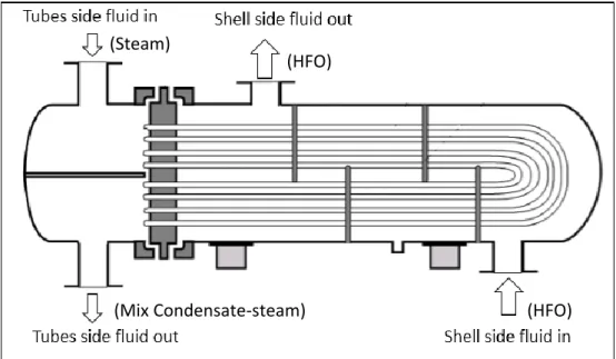
(2) This works focus on the heat exchanger of the fuel treatment unit. As mentioned heat used is provided by a heat recovering boiler, which generate saturated steam in a rage of pressure from 3.2 bar (320 kPa) to 8 bar. The heat exchanger for fuel heating is of the type of shell and tubes, designed for saturated steam up to a pressure of 8 bar (800 kPa). Optimal fuel heating is a key factor to achieve a high efficiency of the engines, in this way it has been decided to improve the heat exchanger design for present operating conditions. In order to accomplish this task it is implemented multi-objective optimization of the thermal and hydraulic design for this exchanger, adopting as optimization criteria, entransy dissipation and total cost.. 2. Thermal and hydraulic designed In the present sections is showed the principal calculations, for heat transfer and pressure drop, for the exchanger shown in the figure 1. Discussing the thermodynamic procedure and the designing methodology.. 2.1. Procedure thermodynamic The first thermodynamic law, for the heat exchanger according to [4] Eq. (1).. (Steam). (HFO). (Mix Condensate-steam). (HFO). Fig. 1. Diagram of mass flows for U-Tubes heat exchanger. 𝑞̇ = 𝑚̇ℎ ∙ ℎ𝑓𝑔 = 𝑚̇𝑐 ∙ 𝐶𝑝,𝑐 (Tc,o − Tc,i ). (1). 𝑞̇ = 𝐶𝑚𝑖𝑛 ∙ 𝜀 ∙ 𝑞̇ 𝑚𝑎𝑥 (2) In [5] is presented the effectiveness and number of transfer unit procedure (𝜀 − 𝑁𝑇𝑈), Eq. (3) indicate the effectiveness and Eq. (4) NTU. 𝜀=. 𝑞̇ 𝑞̇ 𝑚𝑎𝑥. 𝑁𝑇𝑈 =. 𝑈∙𝐴𝑠 𝐶𝑚𝑖𝑛. (3) (4). In heat exchanger analysis, it is also convenient to define another dimensionless quantity called the capacity ratio C as. 𝐶=. 𝐶𝑚𝑖𝑛 𝐶𝑚𝑎𝑥. (5).
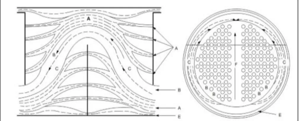
(3) It can be shown that the effectiveness of a heat exchanger is a function of the number of transfer unit NTU and the capacity ratio. 𝜀 = 𝑓(𝑁𝑇𝑈, 𝐶) (6) In the previous reference, the correlations are for all configurations of flow and for all capacity ratio, for this case, is assumed the correlations for all heat exchangers with 𝐶 = 0.. 2.2. Thermal calculation The thermal design fundamentally consists in estimating the heat transfer coefficient in the shell side and tube side. For the shell side the Bell-Delaware method is implemented [6]. First it is estimated for pure crossflow conditions the heat transfer for ideal tube bank Eq. (7), the next step is to affect this magnitude by a group of correction coefficients Eq. (8), which are described below. ℎ𝐼𝑑𝑒𝑎𝑙 =. 𝐽𝑖 ∙𝐶𝑃,𝑐 ∙𝐺𝑠 𝜙. (7). 2⁄3. 𝑃𝑟. ℎ𝑆 = ℎ𝐼𝑑𝑒𝑎𝑙 ∙ 𝐽𝑐 ∙ 𝐽𝐿 ∙ 𝐽𝐵 ∙ 𝐽𝑅 ∙ 𝐽𝑆. (8). ▪ 𝐽𝑐 : This factor take is account baffle cut and central baffle spacing. Its value is 1 for an exchange with no tubes in the window and increase to 1.15 for smalls baffle cut, decrease to 0.65 for large baffle cuts. For good design practice this values is near to 1. ▪ 𝐽𝐿 : Take in count the leakage in Tubes-to-Baffles and Shell-to Baffle (A and B) stream, figure 2. A typical value of this corrector factor is in the range 0.7 to 0.8. ▪ 𝐽𝐵 : Correction factor for the bundle and pass partition bypass (C and F), this factor is about 0.9 to 0.7 depending of tube sheet construction. It can increase from about 0.7 to 0.9 by proper user sealing strips. ▪ 𝐽𝑅 : Correction factor for the large baffle spacing at the inlet and outlet section compare to the central baffle spacing. This factor usually varies from 0.85 to 1. ▪ 𝐽𝑆 : This is a correction factor for advance gradient temperature build-up in laminar flow. This correction is applicable for Reynolds number below 100 and fully effective for Reynolds number below 20; otherwise, it is equal to 1.. Fig. 2. Diagram of stream for the shell side. To estimate the heat transfer coefficient on the tube side the expressions presented in Eq. (9) and Eq. (10) are used [4]. ℎ𝑡 =. ′ 𝑔∙𝜌𝑙 (𝜌𝑙 −𝜌𝑣 )∙𝑘𝑙3 ∙ℎ𝑓𝑔. ′ ℎ𝑓𝑔 =. 𝜇𝑙 (𝑇𝑠𝑎𝑡 −𝑇𝑤 )∙𝐷𝑖 3 ℎ𝑓𝑔 + 𝐶𝑝,𝑙 (𝑇𝑠𝑎𝑡 8. (9) − 𝑇𝑤 ). (10).
(4) The application of the Eq. (9) and Eq. (10) in this case, for the calculation of the heat transfer coefficient on the tubes side, results in a numerical error significantly big. However despite the uncertainty we can assure that for this case, due to the condensation process, the heat transfer coefficient on the tubes side is higher than on the shell side. As shown in figure 1, fuel oil flow on shell side, being the controlling film, due to the high viscosity of this substance and because no phase change occur. The global heat transfer coefficient is strongly determined for the controlling film Eq. (11) [5]. 1 𝑈0 ∙𝐴0. =. 1 ℎ𝑠 ∙𝐴𝑠. +. 𝑅𝑠 𝐴𝑠. +. ln(𝐷0 ⁄𝐷𝑖 ) 2𝜋∙𝑘𝑤 ∙𝐿. +. 𝑅𝑡 𝐴𝑡. +. 1. (11). ℎ𝑡 ∙𝐴𝑡. 2.1. Hydraulic design In this section is presented equations for the pressure drop for the shell side and tubes side, Eq. (12) showed the pressure drop for the shell side [6]. ∆𝑃𝑠 = [(𝑁𝑏 − 1)∆𝑃𝑏,𝑖𝑑 ∙ 𝜁𝐵 + 𝑁𝑏 ∙ ∆𝑃𝑏,𝑖𝑑 ]𝜁𝐿 + 2 ∙ ∆𝑃𝑏,𝑖𝑑 (1 +. 𝑁𝑟,𝑐𝑤 𝑁𝑟,𝑐𝑐. ) 𝜁𝐵 ∙ 𝜁𝑆. (12). In the above equation is taken into account the pressure drop in the crossflow sections, in the windows of the baffles. This equation is affected by a correction coefficient group. ▪ 𝜁𝐿 : Correction factor for the tubes-to-baffle and baffle-to-shell leakage (A and E) streams. Usually vary from 0.4 to 0.5, although lower values are possible with small baffle spacing. ▪ 𝜁𝐵 : Correction factor for bypass flow (C and F) streams, depending of type construction and number of sealing strips, variation range is from 0.5 to 0.8. ▪ 𝜁𝑆 : Correction factor for inlet and outlet sections, having unequal baffle spacing from that of the central section. This varies from 0.5 to 2. The pressure drop for tubes side is estimated for Eq. (13) presented in [7]. ∆𝑃𝑡 =. 𝑓𝑡 ∙𝐿∙𝐺𝑡2 ∙𝑁𝑝 2𝜌𝑡 ∙𝜙𝑡. +. 4𝐺𝑡2 ∙𝑁𝑝 2𝜌𝑡. (13). In Eq. (11) the first term corresponds to the pressure drop caused by fluid friction inside the tubes and the second term takes into account the change in direction of fluid (U-Tubes), not taken into account the losses in the inlet and outlet nozzles. The Bell-Delaware design methodology is widely used for estimated heat transfer and pressured drop for the shell side [8-14].. 3. Optimization design of shell and tubes exchanger To optimize the previously proposed design is implemented an elitist genetic algorithm NSGA-II in Octave. Minimizing the number of entransy dissipation and total cost, subject to the following set of constraints. ▪ Length of the tubes in the range 1.4 to 1.6 m. ▪ Cutting percent deflectors 15-35. ▪ Outside tubes diameter in the range 0.0125 to 0.0508 m. ▪ Fraction of the spacing of the baffles and the shell inside diameter of 0.2 to 1. ▪ Number of tubes in the range 150 to 230. ▪ Pressure drop in the shell side that less 30 kPa. ▪ Pressure drop in the tubes side that less 1.5 kPa. ▪ The fuel outlet temperature in the range of 118℃ to 134℃. This set of constraints respond to geometric constraints on where the equipment is installed, tubes standard [15], operating conditions and common practices in the design of heat transfer equipment. A major constraint is the viscosity of the fuel outlet which should be in the range of 12 to 18 cSt, this corresponds to a temperature range of 134 to 118℃..
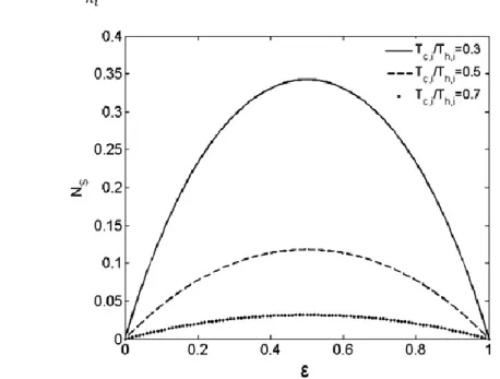
(5) 3.1. Objective functions Traditionally the optimization of thermal systems is supported by exergy principles described in [1617], these authors define the principle of minimum energy dissipation and minimum entropy generation [18]. Based in those principle, for a thermal system in steady state the entropy generation should be minimum. According to [12], the above definition is not in correspondence with the optimum heat exchanger. Bejan [19-21] has studied the exergy loss for the heat transfer of a fluid across a finite temperature difference in a conduct with friction, defining the entropy generation number. The analysis applying the result of the mentioned study in a counter flow heat exchanger showed that entropy generation number approaches to zero in two limits: when the effectiveness approaches unity 𝜀 → 1 or the number of transfer units approaching to infinity 𝑁𝑇𝑈 → ∞, which represents the ideal limit of zero driving temperature difference, and when effectiveness approaches zero 𝜀 → 0 or number transfer unit approaches to zero 𝑁𝑇𝑈 → 0, which represent heat transfer surface approaching to zero. As shown in Figure 3 the number of generation of entropy has a symmetrical behaviour, where not always the minimum entropy generation number corresponds to a maximum effectiveness. Bejan called this phenomenon the paradox of entropy generation. For this problem, the entropy generation number is not an appropriate criterion for optimizing the design of heat exchangers. About the year 2000, in analogy to the electrical conduction, a new principle called “Entransy” arises [22], this property is the ability of the material to transfer heat. In this paper the first objective function is entransy dissipation number, for heat exchanges in single phase the equations are presented in [23]. In the case study presented a phase change of the fluid occur. And single phase equations are not applicable. Taking from [23] the equation for the cold fluid of single phase and developing the equation for hot fluid with phase change, the equations for entransy balance of the heat exchanger can be defined according to Eq. (14). 𝑇𝑐,𝑜 ℎ𝑜 (14) ∫ 𝑚̇𝑐 𝐶𝑝,𝑐 𝑇𝑐 𝑑𝑇𝑐 = − ∫ 𝑚̇ℎ 𝑇ℎ 𝑑ℎ + 𝐺̇𝑑𝑖𝑠𝑠∆𝑇 𝑇𝑐,𝑖. ℎ𝑖. Fig. 3. Relationship between Ns vs. 𝜀 for a counterflow heat exchanger. Integrating from inlet to outlet the above equation and grouping both members is obtained the entransy dissipation for heat transfer Eq. (15). 1 2 2 𝐺̇𝑑𝑖𝑠𝑠∆𝑇 = 𝑚̇ℎ 𝑇ℎ (ℎ𝑖 − ℎ𝑜 ) + 𝑚̇𝑐 𝐶𝑝,𝑐 (𝑇𝑐,𝑖 − 𝑇𝑐,𝑜 ) (15) 2. The entransy dissipation for the cold fluid of single phase and entransy dissipation for the hot fluid with phase change, corresponding to the irreversibility introduced by fluid friction in the process of heat transfer is quantified by Eq. (16)..
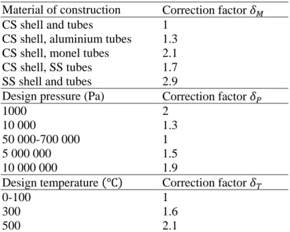
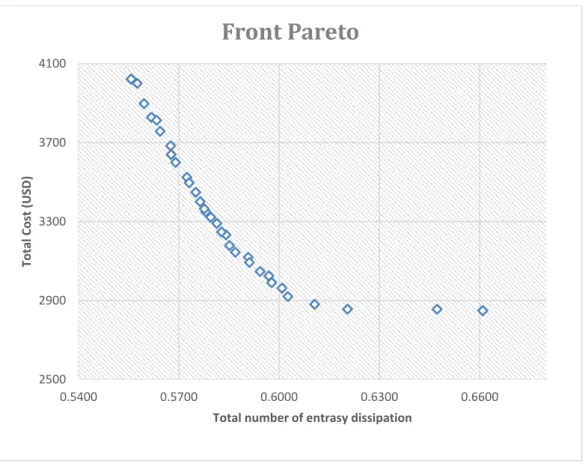
(6) ∆𝑃 (𝑇 −𝑇 ) 𝑃 𝐺̇𝑑𝑖𝑠𝑠∆𝑃 = 𝑚̇𝑐 𝑠 𝑐,𝑜𝑇𝑐,𝑜𝑐,𝑖 − 𝑚̇ℎ 𝑝𝑠 𝑣̅ 𝑙𝑛 ( 0 ) 𝜌𝑠 𝑙𝑛( 𝑇. 𝑐,𝑖. 𝑝𝑖. ). (16). Finally is obtained, the dimensionless dissipation entransy number for heat transfer and friction flow according to Eq. (17), Eq. (18) and the total entransy dissipation number Eq. (19). 𝐺 ∗ 𝑑𝑖𝑠𝑠∆𝑇 = 𝐺 ∗ 𝑑𝑖𝑠𝑠∆𝑃 =. 𝐺̇𝑑𝑖𝑠𝑠∆𝑇. (17). 𝑞̇ (Th,i −Tc,i ) 𝐺̇𝑑𝑖𝑠𝑠∆𝑃. (18). 𝑞̇ (Th,i −Tc,i ). 𝐺 ∗ 𝑑𝑖𝑠𝑠𝑇𝑜𝑡𝑎𝑙 = 𝐺 ∗ 𝑑𝑖𝑠𝑠∆𝑇 + 𝐺 ∗ 𝑑𝑖𝑠𝑠∆𝑃 (19) In the Eq. (17) and Eq. (18) the term 𝑞̇ (Th,i − Tc,i ) is the maximum entransy dissipation. The second objective function is the total cost Eq. (20), according to [24] this estimates the cost of initial investment Eq. (21) and operating cost Eq. (22). 𝑖(1+𝑖)𝑛. 𝑇𝐶 = 𝑃𝐶 (1+𝑖)𝑛. −1. + 𝑂𝐶 𝐴. 0,68. 𝑃𝐶 = 3,28 ∙ 104 ( 𝑠 ) 80. 𝑂𝐶 =. (20) 𝛿𝑀 𝛿𝑃 𝛿𝑇. (𝐸𝑠 +𝐸𝑡 )𝑜𝑝∙𝑒𝑐 1000. (21) (22). The corrections factors for Eq. (19) are showed in table 1 and electricity price (ec) assumed is 0.15(𝑈𝑆𝐷⁄𝑘𝑊 ∙ ℎ). Table 1. The capital cost factors. Material of construction Correction factor 𝛿𝑀 CS shell and tubes 1 CS shell, aluminium tubes 1.3 CS shell, monel tubes 2.1 CS shell, SS tubes 1.7 SS shell and tubes 2.9 Design pressure (Pa) Correction factor 𝛿𝑃 1000 2 10 000 1.3 50 000-700 000 1 5 000 000 1.5 10 000 000 1.9 Design temperature (℃) Correction factor 𝛿𝑇 0-100 1 300 1.6 500 2.1. 4. Results and discussions Applying the principles of entransy dissipation and the empirical equations presented above for total cost estimation an elitist genetic algorithm NSGA-II was implemented. Pareto front shown in figure 4 is obtained. For this case, in advantage over single-objective optimization, the multi-objective optimization displays a set of solutions, bean the Pareto front a versatile tool for this applications, although in some cases this is a problem because of necessary decisions making process to select the best solution for the design..
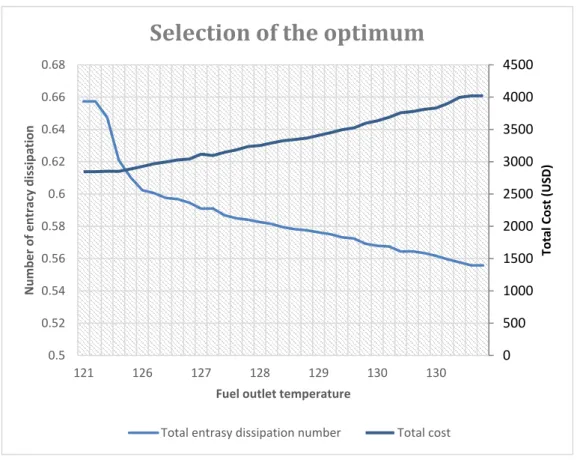
(7) According to the Pareto front obtained, the total number of entransy dissipation decrease as costs increase. This occur because the NTU depends largely on the overall coefficient of heat transfer and the heat transfer surface, and also due to the effectiveness depends on the number of units transferred. High effectiveness corresponds to an area of large heat transfer or high pressure drop which would make the cost increases.. Front Pareto 4100. Total Cost (USD). 3700. 3300. 2900. 2500 0.5400. 0.5700. 0.6000. 0.6300. 0.6600. Total number of entrasy dissipation. Fig. 4. Pareto front for the optimization. In order to make the best selection is recommended the following criteria, select the equipment with the highest heat transfer rate at the minimum cost. For this case is used the graph shown in Figure 5, where it can be seen that the best solutions are those where the fuel outlet temperature is about 125℃. These heat exchangers are those with a high rate of heat transfer at minimal cost. In the table 2 is showed the decisions vector for the best solutions according to figure 5, in Table 3 a set of parameters of interest of the thermal and hydraulic performance are given. Table 2. Vector decisions for the best solutions. 𝐷0 , 𝑚. 𝐿, 𝑚. 𝐿𝑐 , %. 𝐵𝑠. 𝑁𝑇. 0.01588 0.01588 0.01588 0.01588. 1.601 1.620 1.646 1.632. 19.34 17.99 18.84 17.96. 0.34 0.27 0.21 0.21. 150 151 151 156. According to the previously arguments the best effectiveness of the heat exchangers is synonymous of a less dissipation of entransy and low number of entransy dissipation. The ideal selection for this operating conditions correspond to a heat exchanger with the maximum effectiveness, but it was selected a design with an effectiveness equal to 0.76. This selection was made taking in to account not only operating conditions, but also maximum effectiveness involving the minimal cost was.
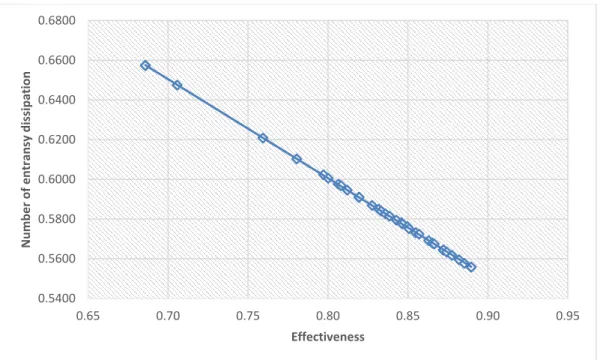
(8) considered. In the figure 6 is showed the dependence of the entransy number dissipation and efficiency for all solutions offered by Pareto front. Analysing figure 6 it can be seen, that more effectiveness correspond to lower number of entransy dissipation. The main geometrical parameters for the selected design are shown in Table 4.. 0.68. 4500. 0.66. 4000. 0.64. 3500. 0.62. 3000. 0.6. 2500. 0.58. 2000. 0.56. 1500. 0.54. 1000. 0.52. 500. Total Cost (USD). Number of entracy dissipation. Selection of the optimum. 0. 0.5 121. 126. 127. 128. 129. 130. 130. Fuel outlet temperature Total entrasy dissipation number. Total cost. Fig. 5. Selection of the optimum design. Table 3. Principal performance thermal-hydraulic parameter. ∗ 𝐺𝑡𝑜𝑡𝑎𝑙. 𝑇𝐶, 𝑈𝑆𝐷. 𝑇𝑐,𝑜 , ℃. 𝜀. 𝑁𝑇𝑈. 𝑈𝑐 ,. 0,6208 0,6103 0,6023 0,6005. 2851 2887 2926 2969. 125 126 126 127. 0,76 0,78 0,80 0,80. 1,42 1,52 1,60 1,61. 360 377 390 384. 𝑊 ∙ ℃). (𝑚2. ∆𝑃𝑠 , 𝑘𝑃𝑎 8,53 9,60 23,00 13,68. ∆𝑃𝑠 , 𝑘𝑃𝑎 0,18 0,18 0,18 0,17.
(9) 0.6800. Number of entransy dissipation. 0.6600 0.6400 0.6200 0.6000 0.5800 0.5600 0.5400 0.65. 0.70. 0.75. 0.80. 0.85. 0.90. 0.95. Effectiveness. Fig. 6. Dependence number entransy dissipation and effectiveness. Table 4. The main geometrical parameter. 𝐷0 , 𝑚. 𝐿, 𝑚. 0.01588 1.601. 𝐿𝑐 , %. 𝑁𝑇. 𝐿𝑏𝑐 , 𝑚. 𝐷𝑆 , 𝑚. 𝑁𝐵. 𝑁𝑃. 𝑃𝑡 , 𝑚. 19.34. 150. 0.101. 0.2996. 15. 2. 0.01985. 5. Conclusions In this paper, the entransy dissipation theory is used for a multi-objective optimization, instead of the principle of minimum entropy generation. A set of solutions was obtained, the solutions found matches with the design principles found in the consulted literature, in all cases increasing effectiveness decreases the number of entransy dissipation. Finally, for the designs obtained is selected the equipment with maximum heat transfer speed and minimum cost, this equipment ensures a fuel outlet temperature in the range of operating conditions.. Nomenclature 𝐴 heat transfer surface, 𝑚2 𝐶 thermal capacitance, 𝑊 ⁄℃ 𝑐𝑝 specific heat, 𝑊 ⁄(𝑘𝑔 ∙ ℃) CS carbon steel 𝐷𝑠 shell inside diameter, m 𝐸 pumping power, 𝑘𝑊 Ec electric cost, 𝑈𝑆𝐷⁄𝑘𝑊 ∙ ℎ 𝑓 friction factor G fluid mass velocity, 𝑘𝑔⁄(𝑚2 ∙ 𝑠) 𝐺̇𝑑𝑖𝑠𝑠∆𝑇 entransy dissipation for heat conduction, 𝑊 ∙ ℃ 𝐺̇𝑑𝑖𝑠𝑠∆𝑃 entransy dissipation for pressure drop, 𝑊 ∙ ℃ 𝐺 ∗ entransy dissipation number.
(10) ℎ specific enthalpy, 𝑊 ⁄𝑘𝑔 HFO Heavy Fuel Oil ℎ𝑖𝑑𝑒𝑎𝑙 ideal heat transfer coefficient, 𝑊 ⁄(𝑚2 ∙ ℃) k thermal conductivity, 𝑊 ⁄(𝑚 ∙ ℃) 𝑚̇ mass flow, kg/s 𝑁𝑏 number of baffle 𝑁𝑇𝑈 number transfer units 𝑁𝑝 number of passes Nr Number of effective tubes rows OC operation cost, USD 𝑜𝑝 operate period, year 𝑃𝐶 capital cost, 𝑈𝑆𝐷 𝑃𝑡 tube pitch, m 𝑃𝑟 Prandalt number 𝑞̇ heat flow, W 𝑇 temperature, ℃ R Fouling factor, 𝑚2 ∙ ℃⁄𝑊 𝑈0 Overall heat transfer coefficient, 𝑊 ⁄𝑚2 ∆𝑃 pressure drop, Pa ∆𝑃𝑏,𝑖𝑑 ideal pressure drop for tube bank, Pa L Longitude, m Greek symbols ε effectiveness ϕ viscous correction coefficient ρ density, kg⁄m3 Subscripts and superscripts min minimum max maximum s shell side c,o cold outlet c,i cold inlet l liquid v steam sat saturation w wall fg phase change cc crossed during flow through one crossflow section cw during flow through one window zone in a segmental baffled shell-and-tube heat exchanger h hot side t tubes side. References 1.. De Cuba, A.E., Oficina Nacional de Estadísticas. Various years. Havana, 2013..
(11) 2.. 3. 4. 5. 6. 7. 8.. 9. 10. 11.. 12. 13. 14.. 15. 16. 17. 18. 19. 20. 21. 22. 23. 24.. Zhang, J.-F., Y.-L. He, and W.-Q. Tao, 3D numerical simulation on shell-and-tube heat exchangers with middle-overlapped helical baffles and continuous baffles–Part I: Numerical model and results of whole heat exchanger with middle-overlapped helical baffles. International Journal of Heat and Mass Transfer, 2009. 52(23): p. 5371-5380. Master, B.I., K.S. Chunangad, and V. Pushpanathan, Fouling mitigation using helixchanger heat exchangers. 2003. Incropera, F.P., Introduction to heat transfer. 2011: John Wiley & Sons. Cengel, Y.A., S. Klein, and W. Beckman, Heat transfer: a practical approach. 1998. Shah, R.K. and D.P. Sekulic, Fundamentals of heat exchanger design. 2003: John Wiley & Sons. Kuppan, T., Heat exchanger design handbook, 2000, Marcel Dekker, Inc. Fesanghary, M., E. Damangir, and I. Soleimani, Design optimization of shell and tube heat exchangers using global sensitivity analysis and harmony search algorithm. Applied Thermal Engineering, 2009. 29(5): p. 1026-1031. Guo, J. and M. Xu, The application of entransy dissipation theory in optimization design of heat exchanger. Applied Thermal Engineering, 2012. 36: p. 227-235. Guo, J., M. Xu, and L. Cheng, The application of field synergy number in shell-and-tube heat exchanger optimization design. Applied Energy, 2009. 86: p. 2079-2087. Leoug, K., K. Toh, and Y. Leong, Shell and tube heat exchanger design software for educational applications. International Journal of Engineering Education, 1998. 14(3): p. 217224. Qian, X. and Z. Li, Analysis of entransy dissipation in heat exchangers. International Journal of Thermal Sciences, 2011. 50(4): p. 608-614. Sanaye, S. and H. Hajabdollahi, Multi-objective optimization of shell and tube heat exchangers. Applied Thermal Engineering, 2010. 30(14): p. 1937-1945. Wildi‐Tremblay, P. and L. Gosselin, Minimizing shell‐and‐tube heat exchanger cost with genetic algorithms and considering maintenance. International journal of energy research, 2007. 31(9): p. 867-885. Association, T.E.M., Standards of Tubular Exchanger Manufacturers Association. 1959: TEMA. Machlup, S. and L. Onsager, Fluctuations and irreversible process. II. Systems with kinetic energy. Physical Review, 1953. 91(6): p. 1512. Onsager, L., Reciprocal relations in irreversible processes. II. Physical Review, 1931. 38(12): p. 2265. Prigogine, I., Introduction to Thermodynamics of Irreversible Processes (3rd edn.) Interscience. New York, 1967: p. 23-25. Bejan, A., The concept of irreversibility in heat exchanger design: counterflow heat exchangers for gas-to-gas applications. Journal of heat transfer, 1977. 99(3): p. 374-380. Bejan, A., General criterion for rating heat-exchanger performance. International Journal of Heat and Mass Transfer, 1978. 21(5): p. 655-658. Bejan, A., Second-law analysis in heat transfer and thermal design. Adv. Heat Transfer;(United States), 1982. 15. Guo, Z.-Y., H.-Y. Zhu, and X.-G. Liang, Entransy—a physical quantity describing heat transfer ability. International Journal of Heat and Mass Transfer, 2007. 50(13): p. 2545-2556. Xu, M., The thermodynamic basis of entransy and entransy dissipation. Energy, 2011. 36(7): p. 4272-4277. Allen, B. and L. Gosselin, Optimal geometry and flow arrangement for minimizing the cost of shell‐and‐tube condensers. International Journal of Energy Research, 2008. 32(10): p. 958-969..
(12)
Figure
+4
Documento similar
We seek to characterize the transport in a time-dependent flow by identifying coherent structures in phase space, in particular, hyperbolic points and the associated unstable and
If the concept of the first digital divide was particularly linked to access to Internet, and the second digital divide to the operational capacity of the ICT‟s, the
1. S., III, 52, 1-3: Examinadas estas cosas por nosotros, sería apropiado a los lugares antes citados tratar lo contado en la historia sobre las Amazonas que había antiguamente
Since such powers frequently exist outside the institutional framework, and/or exercise their influence through channels exempt (or simply out of reach) from any political
Of special concern for this work are outbreaks formed by the benthic dinoflagellate Ostreopsis (Schmidt), including several species producers of palytoxin (PLTX)-like compounds,
In the previous sections we have shown how astronomical alignments and solar hierophanies – with a common interest in the solstices − were substantiated in the
Li, Investigation on the flow and convective heat transfer characteristics of nanofluids in the plate heat exchanger, Experimental Thermal and Fluid Science 76
A characterization of the heat exchanger performance is necessary to assess the relation between heat transfer enhancement and augmentation of power consumption (pumping and
