CBTC TEST SIMULATION BENCH.
J.M. Mera, I. Gómez-Rey, E. Rodrigo
CITEF (Railway Technology Research Centre); Escuela Técnica Superior de Ingenieros Industriales. Universidad Politécnica de Madrid.José Gutierrez Abascal, 2 28006 Madrid, SPAIN.
Tel. +34 91 336 3212 e-mail: citef.jmmera@etsii.upm.es
Abstract
Due to its safety characteristics, signalling equipment requires a great amount of testing and validation during the different stages of its life cycle, and particularly during the installation and commissioning of a new line or upgrade of an existing line, the latter being even more complicated due to the short engineering periods available overnight.
This project aims to develop a tool to reduce the above-mentioned efforts by simulating the CBTC trackside, fulfilling the interfaces between subsystems and elements of these subsystems, and using some real elements.
In this way, a testing environment for signalling equipment and data has been developed for the CBTC system. The aims of the project that were set out at the beginning of the development and completed with the present simulator are as follows:
• Real CBTC equipment trials and integration: CBTC on-board
equipment, CBTC Radio Centre, etc.
• Other signalling elements trials and integration: Interlockings and
SCCs.
• CBTC track data validation.
This system has been developed, and is currently adding new modules and functionalities, for companies of the Invensys Group: Westinghouse Rail Systems in the UK and Dimetronic Signals in Spain, which are using it for the new CBTC lines under their responsibility.
Keywords: Computer techniques, management and languages (Simulation), Advanced train control (CBTC), Equipment test.
1
Introduction
The increasing expansion of underground railway networks seen in recent years to meet the growing demand has highlighted the need to integrate new signalling and rail traffic management systems, like CBTC [1,2], which enable line capacity to be increased as well as line operating safety. Therefore, in order to obtain a safe and reliable operation, numerous tests need to be performed, but the high costs of infrastructures as well as rolling stock make it extremely difficult to immobilize both in order to use them for testing and training. For this reason, and because sometimes it is impossible to create high risk situations to demonstrate the procedure to follow, the use of simulators is more than justified in the world of railways. Within the scope of railway simulators, we can find different functionalities, such as driving simulators and operational simulators, for testing real equipment, and analyzing data, etc. .
The main aims of the project with which we are dealing, are to develop a tool to reduce the effort needed to bring a new line into service, and at the same time avoid immobilizing infrastructure and rolling stock. The tool may even be used for carrying out tests prior to the physical existence of the new line. For this reason, our simulator is included among those developed for testing real equipment and analyzing data. In order to develop the simulator, all the elements needed as well as their real interfaces have been simulated, it being possible to replace each of these elements by their real equivalents.
In order to attain these goals, a test environment for signalling and data equipment has been developed within the CBTC system. The aims set at the start of the project, which are being completed with this simulator, are as follows:
• Integration and testing of real CBTC equipment, such as: BPs, ATP,
etc.
• Integration and testing of other signalling elements, such as:
Interlockings, SCCs, etc.
2
SYSTEM ARCHITECTURE DESIGN
Analysis Tool
Train Systems Automatic
Driver
BP
Interlocking
APR Balise
Track Circuit
Signals
Switches
Planning and Control Desk
Dynamic TIU
Infrastructure
Automatic Train
SCC
Real Data ATP
APR Reader Track Circuit Code Reader Antenna
Radio
DMI
Figure 1: General layout of the CBTC Simulator.
The system is based on the ERTMS/ETCS simulator developed for Invensys Rail [3,4,5], and shares several of its modules with it. The most important elements that have been reused are:
• Planning and Control Desk (PCD): this application allows the Simulator
user to: generate, configure, launch, etc., the different scenarios. It has had to be adapted to offer the possibility to generate and work with both an ERTMS and a CBTC scenario.
• Infrastructure: this is automatically generated from a configuration file
containing a description of all the elements making up the infrastructure, using a specified language: track circuits, points, balises, signals, etc. The logic of each of these elements as well as their functionality has also been simulated. Specific infrastructure components have been developed for CBTC.
• Automatic Trains: it is possible to have up to thirty automatic trains
can be checked. For example, the correct working of the BP with several trains connected to it can be checked.
Of the new elements developed for adaptation to CBTC, the following are particularly important:
• APR Balise: these elements contain the telegrams from the APR
track-side balises and send their contents when stimulated by the simulated train.
• Track Circuit with Speed Codes: theses elements simulate track circuit
occupation, whether it be untimely or due to an oncoming train. In addition, they load a speed code in accordance with the conditions contained in the interlocking and this is sent to the train when it invades the interlocking.
• Interfaces with the real modules: since various types of real equipment
have had to be integrated, like the ATP or the DMI, elements have needed to be developed that can send and/or receive, as need be, the data that each piece of equipment must exchange with the simulated part.
• Analysis Tool: this tool allows analysing the data loaded in the BP. By
taking the messages exchanged between an automatic train and the BP, a series of graphs and checks are generated that can easily check whether or not the engineering rules with which the signalling was designed are being met, as well as determining if the BP is performing properly under the circumstances specified for the analysis.
The modules that have been integrated are described below:
• ATP: the on-board train equipment has been integrated in its Host
version, that is, in its software version to be run in a PC.
• DMI: the driver interface has also been integrated in its Host version.
• BP: the Block Processor Host has also been included in the simulator.
TCP/IP
Communications Module
Body of the Application
Figure 2: General layout of an application.
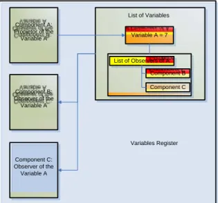
The use of the Components Technology developed by CITEF has also been maintained in respect of the base system. One component is a DLL (Dynamic Linked Library) which has a specific function. For example, a balise needs to send its content to a train when stimulated by such. Each real element has its equivalent in a component. The components involved in each application are stored in a Components Container called a Variables Register, which enables them to communicate with one another through the exchange of variables, as can be seen in the diagram in Figure 3.
Component A: Propietor of the Variable A
Component B: Observer of the Variable A
Component C: Observer of the Variable A
List of Variables Variable A = 7
Component C Component B List of Observers of A
Variables Register
3
INTERFACES WITH REAL EQUIPMENT
A new inter-application communication mode has had to be developed to achieve interaction with real equipment, such as the ATP Host and the DMI Host. These communications are socket-based.
The sockets enable any data flow to be reliably and orderly exchanged between two applications. To define a socket, an IP address and a port are necessary, apart from setting up a transport protocol capable of being interpreted by both applications. Since IP addresses are being used, sockets can be used between applications that are running in different computers. In the example in Figure 4, it can be seen that applications A and B are connected by a socket that joins the Port2 ports of the IP1and IP2 IPs. A socket can be made to look like a direct pipeline between two applications so that one will supply the data that the other needs to receive.
The sockets enable a client-server architecture to be implemented. The name client is given to the application that initiates communication and server to the application waiting for the other to initiate said communication. That is, in the example in Figure 4, if application A makes a communication request to application B, and application B accepts it, the socket is established between both, and A plays the role of client and B the role of server.
Application A (client) IP1 Port1 Port3 Port2 Application B (server) IP2 Port1 Port3 Port2 Socket
Figure 4: Scheme of a socket.
In spite of the fact that using sockets allows two-way communication, the developed system uses a one-way system so that the client only sends data and the server only receives data. Where two-way communication is required two sockets are implemented so that both applications are servers and clients at the same time. In Figure 5, applications A and B are connected to two sockets. Socket 1 is used to send data from B to A and inside it. A is the server and B the client; to the contrary, Socket 2 is used to send data from A to B and inside it. A is the client and B the server.
Application A IP1 Port1 Port5 Port3 Application B IP2 Port2 Port6 Port4 Socket 1 Socket 2
The real equipment integrated is accompanied by a simulation layer that lets sockets be implemented in it and serves as a data exchange interface in a format that is adapted to the core of the real equipment.
Figure 6 shows the general layout of communications with the integrated real equipment. The ATP and the DMI are the elements for which sockets have had to be used.
The design developed by CITEF in the simulator incorporates new components whose function is to replicate the data handled by the real equipment by means of communication with a central component called an ATP Router. It is this that is connected to the ATP and the DMI through sockets. The elements developed for this purpose in the simulator are detailed below, indicating the kind of data exchanged with the ATP Router:
• TIU Socket: sends/receives the discreet signals handled by the ATP. For
example, when the driver operates the emergency brake, the TIU receives this data, which in turn is received by the TIU Socket, which transmits it to the ATP Router for it to be sent to the ATP.
• Dynamic Socket: sends the speed and forward movement data that
calculates the dynamics for the ATP Router to be able to send it to the ATP.
• APR Socket: sends the telegrams from the balises the train passes over
on its journey for them to be transmitted to ATP.
• Socket Speed Codes: sends the speed codes that the ATP must receive
as the train keeps occupying track circuits.
The ATP Router establishes the following sockets with the DMI and the ATP:
• ATP Despatch Socket: all the data required to be received by the ATP is
sent through this socket; that is, balise telegrams, discreet, dynamic speed codes, messages from the BP and messages from the DMI.
• DMI Despatch Socket: the data to be shown to or requested of the
driver at any instant as indicated by the ATP at any instant is sent through this socket.
• DMI Reception Socket: the actions taken by the driver on the DMI to be
transmitted to the ATP are received from this socket.
• ATP Reception Socket: three types of data are received; the messages
APR Balises
Track Circuits with Speed Codes
Signals
Switches
Infrastructure
Router ATP
Train Systems
TIU
Dynamic
Socket APR Socket Dynamic Socket TIU
Socket Speed Codes
BP Antenna
Radio
ATP DMI
4
DATA ANALISIS
One of the most important parts of the development undertaken is the Analysis Tool. This tool can be used to program analyses of the data exchanged between the BP and the ATP.
The process followed to achieve this purpose is described below:
• A scenario is taken without automatic trains and without any set routes.
• In the real SCC the user sets the route to be analysed.
• The interlocking receives the order to set the route and sends it to the
field elements that are positioned to correspond to the route in question, and when the conditions set are met, the interlocking sends a signal to the BP to indicate that the route has been authorised. The Analysis Tool is listening to the communication between the interlocking and the BP, and is thus able to detect which route has been set.
• When the route has been authorised, the user can request an analysis of
the route in question, selecting the required analysis options.
• A train is automatically inserted in the simulator forward of the set route and begins to run. The train must receive 2 APR balises before entering the route. On receipt of the first balise, the train must initiate communications with the BP, and after the second APR, the BP can send the train a movement authorisation.
• Throughout the simulation, the messages exchanged by the train and the
BP are listened to by the Analysis Tool, and, so, the tool can decide when the conditions set for the analysis have been met. At this moment, the train will brake automatically, shut off communications with the BP, and will be eliminated from the scenario.
• The Analysis Tool will analyse the messages that it has been listening to
during the simulation and generate the graphs and checks requested by the user.
5
ADVANTAGES AND FUNCTIONALITY OF THE
SYSTEM
It may, therefore, be stated that the main advantages and functionalities of the system described in this article are as follows:
• A reduction in the efforts required to bring lines equipped with the
CBTC system into service.
• It offers the possibility to test different configurations of a single
scenario to see which option is most advantageous.
• Since neither the infrastructure nor the rolling stock need be
immobilized in order to carry out tests, a considerable reduction in costs is obtained.
• Since the same interfaces are used as with the real equipment, this
the possibility of simultaneously including one or more pieces of real equipment.
• It may be used to verify trackside data before it is installed, and in
addition, if need be, obtain results showing where the erroneous data is located.
Figure 7: Some snapshots of the simulation system.
6
FUTURE DEVELOPMENTS
It is planned to extend the system in several stages in order to achieve the following objectives:
• To test real Target equipment, that is, the hardware version with the
configuration to be installed on the track. To perform this, there will be a stage where the ATP, DMI and BP Host will be replaced by Target equipment.
• Target interlockings will also be tested and will also be required to be
integrated.
• To use the system as a driving simulator by incorporating a virtual cab
and a visual environment.
• To test the real ATO equipment, both in its Host version and Target
7
CONCLUSIONS
Since the CBTC Test Simulation Environment developed by CITEF implement exactly the same interfaces built into real equipment, it can guarantee that the behaviour of the simulated and real equipment is absolutely identical.
Moreover, if we take into account that the use of simulators in a railway environment has been fully justified throughout this article, and more so in this particular example of a CBTC environment, we may state that using this test bench tool is an overriding guarantee for bringing new CBTC lines into service as well as ensuring that the different track and on-board equipment will run smoothly under absolutely any circumstances.
It is also a tool for preparing data, testing and detecting any possible failures in track data.
We may state that in spite of the development costs for this type of tool, the cost of track tests is reduced considerably thanks to this simulation environment, since the number of track tests is reduced, thereby reducing the use of infrastructure and rolling stock set aside for this purpose. This cost saving becomes more hidden if it is borne in mind that it is a polyvalent system, as it can be used for any line that implements CBTC.
This system is being developed, and is currently adding new modules and functionalities, for companies of Invensys Rail: IRNE in the UK and IRSE in Spain, which are going to use it for the new CBTC lines under their responsibility.
8
REFERENCES
[1] 1474.1 IEEE Standard for Communications-Based Train Control (CBTC)
Performance and Functional Requirements
[2] 1474.2 IEEE Standard for User Interface Requirements in
Communications-Based Train Control (CBTC) Systems
[3] Gómez-Rey, A, Mera, JM, et al. ERTMS Driving and Operation Simulator
under Distributed Architecture in a Virtual Reality Environment.
Proceedings of ITEC’2001. Lille, France. April 2001.
[4] Mera, JM, Gómez-Rey, I, et al. ERTMS/ETCS TEST SIMULATION
BENCH. 10th International Conference on Computer Aided Design,
Manufacture and Operation in Railway and other Advanced Mass Transit
Systems. COMPRAIL X. Prague, Check Republic. June 2006.
[5] Mera, JM, Gutiérrez, LM, et al. Simulation of the ERTMS / ETCS Railways