Ricardo Perera, Dept. of Structural Mechanics, Technical University of Madrid, José Gutiérrez Abascal 2, 28006 Madrid, Spain, email: perera@etsii.upm.es
Antonio Ruiz, Dept. Of Applied Mathematics, Technical University of Madrid, Alenza 4, 28003 Madrid, Spain
ABSTRACT
Advanced composite materials are increasingly used in the strengthening of reinforced concrete (RC) structures. An updating procedure based on strain-based monitoring of FRP laminates is proposed here to predict the initiation of midspan debonding on FRP-strengthened beams.
INTRODUCTION
Advanced composite materials are increasingly used in the strengthening of reinforced concrete (RC) structures [1]. The use of externally bonded strips made of fibre-reinforced plastics (FRP) as strengthening method has gained widespread acceptance in recent years since it has many advantages over the traditional techniques, especially because of the high strength and modulus of elasticity, improved durability, and low weight of the composite material. Failure of FRP-strengthened RC beams may take a variety of forms including all those associated with conventional concrete beams. However, unfortunately, this strengthening method is often associated with a brittle and sudden failure caused by some form of FRP bond failure. This kind of failure is produced in the form of cover delamination, i.e., along the plane of the steel reinforcement, or FRP delamination, i.e., in the plane along the FRP-concrete interface. Furthermore, failure may be originated at the termination of the FRP material and propagate towards the midspan [2,3] or in the vicinity of flexural cracks in the RC beam and propagate towards the FRP termination [4, 5]. Hence, flexural cracking of the RC beam has a major influence on the overall response of the strengthened member, and it affects the distribution of the stresses in the various constituents of the strengthened member.
As a result, considerable numerical and experimental efforts should be made to capture these phenomena. An updating procedure based on strain-based monitoring of FRP laminates is proposed here to predict the initiation of midspan debonding on FRP-strengthened beams.
An Updating Procedure for Monitoring
Laminates of FRP-Strengthened Beams
DIFFERENTIAL EQUATIONS
Considering first-order shear deformation theory, the axial and transverse displacement field can be expressed as:
0
( , , )= ( , )−
φ
( , )C
u x z t u x t z x t (1)
0
( , , )= ( , )−
φ
( , )+ ( , )FRP
u x z t u x t z x t s x t (2)
( , , )= ( , )
w x z t w x t (3)
where uC, uFRP and w are respectively the axial displacements in RC beam and
FRP plate and the transverse displacement at a material point,
φ
is the curvature-independent rotation of the beam cross-section about the Y-axis and s is the interface slip.The linear constitutive model for the concrete beam and the FRP plate can be expressed as
x C EC x C xz C GC xz C
σ
=ε
τ
=γ
(4)xz FRP GFRP xz FRP
τ
=γ
(5)where the material constants, E and G, are referred to the concrete beam (C) or the external plate (FRP) depending on the material considered.
Applying Hamilton’s principle, the governing equations of the FRP flexural strengthened RC beam are obtained and can be written as
0: 0 0 1 0FRP 11 0,xx 11 ,xx FRP ,xx 0
u I u I I s A u B A s
δ
ɺɺ −φ
ɺɺ+ ɺɺ− +φ
− = (6)0 22 , 22 ,
: 0
δ
ɺɺ− +φ
=xx x
w I w A w A (7)
2 1 0 1 11 0, 11 , 22 , 22 ,
:I I u I FRPs B u xx D xx A wx A BFRPsxx 0
δφ
φ
ɺɺ− ɺɺ − ɺɺ+ −φ
− +φ
+ = (8)0 0 0 1 , 0, ,
: AD AD 0
FRP FRP FRP FRP xx FRP xx FRP xx
AD
G sb
s I s I u I A s A u B
e
δ
ɺɺ+ ɺɺ −φ
ɺɺ− − +φ
+ = (9)and associated force boundary equations can be expressed as
11 0, 11 ,
φ
, = x− x+ FRP xN A u B A s (10)
22 , 22
φ
= x−V A w A (11)
11 0, 11 ,
φ
, = − x+ x− FRP xM B u D B s (12)
*
, 0, φ,
= FRP x+ FRP x− FRP x
where (⋅) denotes temporal derivative. N, V, M and N* are the stress resultants associated with the variables u0, w, φ and s, respectively.
A11, B11, D11, A22, AFRP and BFRP are the stiffness coefficients obtained from
the material properties.
1.3. SPECTRAL ELEMENT
A spectral Timoshenko beam finite element formulation for the problem under consideration has been considered [6]. The generic displacement vector at any point and frequency becomes
{
}
{
}
1
2
8
0 11 18
21 28
31 38
41 48
ˆ ( , ) 0 0
ˆ ( , ) 0 0
ˆ( , ) ( )
ˆ( , )
ˆ( , ) 0
ω
ω
ω
ω
φ
ω
ω
− − − = = … … … … … ⋮ ⋱ ⋱ ⋮ … … … jk x n jk x n n n n jk x nu x R R e
w x R R e
u x A
R R
x
R R e
s x
(14)
where kp+4=-kp (p=1,…,4) are the wavenumbers.
{ }
A n is a vector of eight unknown constants to be determined. This vector can be calculated by imposing the nodal spectral displacements at the two nodes of the element.The dynamic stiffness matrix is formulated by using the force boundary conditions at the nodes of the element.
4. RESULTS
Using the proposed approach the distribution of stresses and strains of strengthened beams has been obtained.
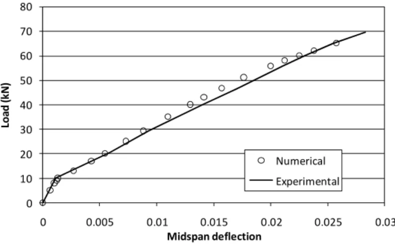
Static predictions, i.e., dynamic computations with the proposed method when frequency tends to zero, have been compared with the experimental results.
The response of the B6 RC beam strengthened by an externally bonded carbon FRP strip, which was tested in [7] has been taken for comparison. The beam was 2.3 m long x 0.2 m wide x 0.15 m deep and was reinforced longitudinally with two bars of 0.008 m diameter over compression side and two bars of 0.010 m diameter over tension side; transversally, stirrups of 0.006 m diameter at every 0.075 m were distributed along the beam. The carbon FRP plate used with the B6 specimen was 1.930 m long and 0.15 m wide and its thickness was 0.0012 m. The beam was subjected to two identical point loads, applied symmetrically at 0.3 m from the middle (four-point bending test), being simply supported on a pivot bearing on one side and a roller bearing on the other side, over a span of 2.1 m.
elements were used, one for each one of the two non-strengthened beam portions in the vicinity of the supports, another one for the beam portion between the applied loads and 20 elements uniformly distributed at the beam portions located between the ends of the FRP plate and the loads.
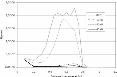
Figure 1 shows the comparison of the spectral model prediction of the load-deflection response of the strengthened beam A-400-2, along with the experimental results. The local behaviour at the adhesive-concrete interface considering flexural cracking of the RC beam is shown in Figure 2 by using the interface-slip evolution under increasing load levels. According to the experimental results, the beam failed as a result of transverse curling of the plates at the midspan. In Figure 2, the maximum peak values of the interface slip are located where there is steel rebar yielding, since, in that case, a sudden increase in FRP strain rate occurs starting from that region. This demonstrates the ability of the proposed method to simulate intermediate debonding failure and, therefore, its feasibility to be used in a damage identification procedure from experimental results.
CONCLUSIONS
A model using spectral elements has been proposed to simulate in a unified way the static and dynamic behaviour of FRP flexural strengthened reinforced concrete beams. The two main characteristics of the proposed approach are its simplicity and its ability in accurate high-frequency modelling. This model can be taken as a starting point to implement a damage identification procedure for this kind of strengthening.
ACKNOWLEDGEMENTS
The writers acknowledge the support for the work reported in this paper from the Spanish Ministry of Education and Science (project BIA2007-67790).
Figure 1. Load-displacement curve 0
10 20 30 40 50 60 70 80
0 0.005 0.01 0.015 0.02 0.025 0.03
Lo
a
d
(
k
N
)
Midspan deflection
Figure 2. Interface slip evolution
REFERENCES
1. Bank LC. Composites for construction: Structural design with FRP materials, first ed. John Wiley and Sons 2006.
2. Yang ZJ, Chen JF, Proverbs D. Finite element modelling of concrete cover separation failure in FRP plated RC beams. Constr. Build. Mater. 2003; 17 (1): 3-13.
3. Pesic N, Pilakoutas K. Concrete beams with externally bonded flexural
FRP-reinforcement: analytical investigation of debonding failure. Compos. Part B-: Eng. 2003; 34(4): 327-338.
4. Sebastian WM. Significance of midspan debonding failure in FRP-plated concrete beams.
J. Struct. Eng. ASCE 2001; 127(7): 792-798.
5. Yao J, Teng JG, Lam L. Experimental study on intermediate crack debonding in FRP-strengthened RC flexural members. Adv. Struct. Eng. 2005; 8 (4): 365-396.
6. Gopalakrishnan S, Ghakraborty A, Roy Mahapatra D. Spectral finite element method, first
ed. Springer, London 2008.
7. Rahimi A, Hutchinson A. Concrete Beams Strengthened with Externally Bonded FRP