Robotic Machine for High-Quality Shotcreting Process
PhD, Samir Nabulsi, AITEMIN, Margarita Salas 14, 28918 Leganés (Madrid), Spain Mr, Angel Rodriguez, AITEMIN, Margarita Salas 14, 28918 Leganés (Madrid), Spain PhD, Olga Rio, CISDEM, CSIC-UPM, Serrano Galvache 4, 28033 Madrid, Spain
Abstract
This paper summarizes the development of the technologies used to produce high quality sprayed concrete layers by ro-botizing a commercial shotcreting machine and automating the process used in the tunnelling construction industry. The proposed method provides the control system with the information of the properties of the pumping process, controlling the quality of the concrete layer by adjusting in real-time the trajectory of the shotcreting machine. Given the unstruc-tured nature of the tunnelling construction method there is an inherent difficulty in the automation of the shotcreting process. A complete description of the implemented control architecture of the shotcreting machine, the automated shot-creting process, the real-time quality layer prediction and the analysis of the tests made in real sites are shown in this pa-per.
1
Introduction
In the underground construction branch of civil engineer-ing and minengineer-ing there are different types of tunnellengineer-ing methods, and one of the major ones, known as drill & blasting, often include the process of concrete spraying -or shotcreting- process. This tunnelling method consists of three main stages: Drilling and blasting, loading and haul-ing of blasted rock and supporthaul-ing of the newly open cav-ity. In the third step, shotcreting is often the method of choice for providing temporary support.
This process consists on spraying concrete mix on the sur-face of the new cavity, quickly creating a supporting struc-ture. The shotcrete surface can be used as temporary sup-port until a final concrete lining is cast, or even as the final lining of the tunnel if additional structural shotcrete is added.
Nowadays, for performing the shotcreting process special-ized machinery is controlled by qualified operators, which create shotcrete layers of specific properties based on their experience. The properties and the quality of the layer de-pend on the type of the lining needed, and basically the quality of the layer is measured in terms of homogeneity and thickness. In the last years there has been an increasing interest on the real time determination of both the homo-geneity and thickness of shotcrete layers. There are both technical and economical reasons that justify this interest: On the one hand there is the need of guaranteeing a mini-mum shotcrete thickness [1], while having the minimini-mum required structural strength. On the other hand, contractors also do not want to place extra shotcrete on the walls, for usually they will not get paid for it.
Additionally the development of different acquisition technologies during the past few years has made plausible the introduction of automation techniques in the under-ground construction process. Different approaches have been described for shotcreting automation and thickness estimation [2][3][4]. The proposed method provides the control system with the information of the properties of the
pumping process, controlling the quality of the concrete layer by adjusting in real-time the velocity of the trajectory of the shotcreting machine.
Figure 1 Sika®-Putzmeister PM-407 [5].
The industrial machine Putzmeister-Sika® PM-407 (see Fig. 1) has been used as a test platform for the develop-ment of the shotcrete automation.
2
Process automation and control
system of the shotcreting machine
In tunnelling, after the advancement (drilling and blasting) stage, shotcrete is used to cover the surface of the roadway to create a support on the working area inside the tunnel. The advancement stage is made by introducing explosives in the face of the tunnel and making a controlled blast. But, as controlled as the blasting can be, the dimensions of the resulting surface are completely unstructured and thus, one of the implicit difficulties involved in the shotcreting proc-ess that has avoided its automation.
Three steps have been defined for the automated shotcret-ing stage:
1. Pre 3D LADAR scan of the working area. 2. Automated shotcreting process.
3. Post 3D LADAR scan and layer quality evalua-tion.
The first step of the automated process is basically done by imaging the working surface of the tunnel with a 3D LADAR scanner (the LIDAC-16 developed by AITEMIN). The information acquired from the first scan is then used by the main control system of the machine to generate the trajectories to shotcreting a layer. Finally a second scan is made in order to evaluate, subsequently, the quality of the layer and the amount of concrete used. This information can also be used to optimise the control parameters of the automatic shotcreting system.
2.1
Robotization of the shotcreting machine
The shotcreting machines are based on manipulators that as an end tool they have a nozzle to spray the concrete fed by a concrete pump. It is to be noted that the best way to spray the starting mix into a wall is by keeping the spray-ing vector perpendicular to the surface of the selected area, at a certain distance that may vary between 1 and 1.5m.Furthermore this type of machinery hasn’t been designed for automation purposes but for manually controlled la-bour. This implies that some additional factors like me-chanical deformations, backlashes, or the control type of the actuators have to be taken into account in the control system of the machine for precise positioning.
The proposed control system has been designed to use the real-time layer thickness estimator and the roadway ge-ometry information to feedback and adapt the trajectory control according to the conditions in order to produce high quality concrete layers.
2.1.1 Mechanical configuration of the manipula-tor
The arm of the shotcreting machine is made of 5 degrees of freedom (DOF) of hydraulically actuated joints (see Fig. 2). The first three are configured as a spherical ma-nipulator (2 rotational and 1 prismatic joint), and the last two rotation joints from the end tool, are specially config-ured to help the operators to maintain a certain orientation without having to move many joints simultaneously. There is an additional sixth joint at the end of the tool that generates an eccentric rotation of the nozzle. This joint was originally design to help the operators to increase the smoothness of the spraying, but it is not going to be taken into account for automatic control purposes and it is con-sidered the nozzle in the centre.
Another property of the system is that it is only possible to control the velocity of the first two DOF according to the control type of its hydraulic valves (see Table 1). The rest of them they just have on/off valves. This configura-tion affects the way the velocity of the movement of the manipulator is controlled (as explained later in section 2.1.2.2).
Figure 2 D-H configuration of the PM – 407 manipulator.
Table 1 D-H Parameters for shotcreting manipulator.
The direct kinematics of every joint is known by applying the Denavit-Hartemberg [6] convention, according to the joint configuration (see Table 1), where the target position will result by adding to a6 the desired distance between the nozzle and the tunnel surface (r). But to control the manipulator in position, velocity and orientation accord-ing to desired target position vector (P), by evaluataccord-ing its inverse kinematics, some details have to be taken into ac-count.
a. b.
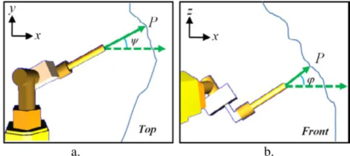
Figure 3 Yaw (ψ) and pitch (ϕ) angles of the nozzle dur-ing spraydur-ing. a) Top view and b) Front view.
First of all, P(O6r,R(ψ,ϕ)) is a vector defined by two ele-ments, the position (X,Y and Z) of and the attitude (ψ,ϕ) for the target of spraying; this elements are specified ac-cording to the coordinate system of the origin of the ma-nipulator (Oo) (see Fig. 3), and they are provided by the LADAR system.
The inverse kinematic problem has been solved using the decoupling technique [7]. As in this problem O6 and the orientation of the nozzle are known, it is possible to solve the position and orientation of the nozzle by evaluating O5 using an analytical approach by the given equation:
Joint i αi ai θi di Ranges Control Type
1 π/2 -a1 θ1 d1 -158
o
- 171o Proportional
2 π/2 0 θ2 0 19
o
- 154o Proportional
3 0 a3 0 d3 0 - 2094 mm On/Off
4 π/2 0 θ4 0 0 - 360
o
On/Off
5 0 0 θ5 -d5 -47
o
- 204o On/Off
-x5 = x6 – (a6Cos(ϕ)* Cos(ψ))
y5 = y6 – (a6Cos(ϕ)* Sin(ψ))
z5 = z6 + a6Sin(ϕ)
The inverse kinematic problem must proceed finding O3. Given the fixed distance O63 = sqrt(a62 + -d52) and its ori-entation γ = atan(-d5,a6), O3 can be directly solved by the equations:
x4 = x3 = x6 – (O63Cos(γ+ϕ)* Cos(ψ)), y4 = y3 = y6 – (O63Cos(γ+ϕ)* Sin(ψ)), and z4 = z3 = z6 + O63Sin(γ+ϕ).
Then, the three first parameters can be evaluated just with the position of O3, indeed θ1 =Atan(O3y ,O3x). In this case there is just one solution for θ1 because of the constraint on the joints. Normally θ1=Atan(O3y ,O3x)+ π is also a
possible solution but if this solution is chosen, it will give automatically a negative solution for θ2and this is not al-lowed by the constraints of the machine.
Hence, there is just a unique θ1 it is possible to evaluate O1 according to the next equation:
O1 = (-a1Cos(θ1), -a1Sin(θ1), L1),
and so is the distance O31. According to this the distance of the prismatic joint can be evaluated by d3 = sqrt(O312 -a32), and finally, θ2 can be evaluated by the equation:
θ 2 = Atan(n,q)-Atan(a3,d3) + π/2
where n = O3 -O1projected on y1 and q = O3 -O1projected on x1.
Now that θ 1, θ 2 and d3 have been found, the transforma-tion matrix T03 can be evaluated and therefore the position and the orientation of O3 are known. Moreover, the matrix between the O3 and O6 is also known according to the transformation matrix T36. In this way it can be deter-mined that θ4 = Atan(T36(1,3),-T36(2,3)) and θ5 = Atan(T36(3,1), T36(3,2)).
The problem with this method is that in order to be cor-rect there is a condition that has to be fulfilled and it is that z3 must be perpendicular to z5 and therefore to z6. This is determined by the geometry configuration of the manipulator and in fact there are very few circumstances in which this condition coincides with the previous in-verse kinematic evaluation.
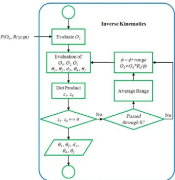
Therefore it is necessary to find an O3 that may fulfils the perpendicular condition between z3 andz6. This problem is solved by recursive iterations where the reference system O6 = O6*Rz(φ) (where Rz(φ) is the rotation matrix or the roll angle of the nozzle) is rotated around z6 until the dot product z3. z6 = 0.
This means that the link between O3 and O5 is rotated around z6 adding in each iteration a constant value to φ, changing the position of O3 and O1, and therefore chang-ing the value of θ1,θ2, d3,θ4 and θ5. Each of these posi-tions must be evaluated every iteration, according to the equations shown before, until the perpendicular condition is satisfied.
This process may take to much CPU time if it is not done with certain logic. For example the direction of the rota-tion may be selected according to the attitude of the noz-zle and the quadrant where it is located.
Additionally, the time of the process may decrease by in-creasing the rate of φ and using statistical strategies to av-erage the value of the product between iterations. This is the case when, for example, the value of the dot product passes through zero between iterations.
Figure 4 Flowchart for the inverse kinematics resolution for the shotcreting machine’s manipulator.
2.1.2 Control architecture
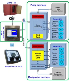
The main control is based on a computer (master control-ler) which, through the information provided by multiple sensors and measurement systems, is responsible for mov-ing the arm of spraymov-ing at a determined velocity by evalu-ating the position and attitude of the nozzle tip with re-spect to the surface of the tunnel, having defined previ-ously the work area and the thickness of the layer. It has a distributed structure which is designed to inter-connect the interfaces that are designed to monitor and control the shotcreting machine, its manipulator and to add additional control elements (see Fig. 5).
It is divided in four main modules: the manipulator’s in-terface, the pumps’ inin-terface, the additional elements (LADAR scanner or the remote control), and the main controller that has a visual based Human Machine Inter-face (HMI), designed for its use in construction sites, and that it is in charge of the control system of automated shotcreting process.
and c) the manual mode, that is the last mode of opera-tion, where the operator uses the remote control to move freely the manipulator but it is assisted by the control sys-tem in order to move the joints with coordinated move-ments instead of one joint at a time (as it is done in the operation without any automation).
Figure 5 Main control architecture.
The last two modes of operations were implemented in case unexpected issues arises inside the tunnel construc-tion process (like faults or water leaks) and the automated control system is not able address them. These modes won’t be discussed further in this document.
2.1.2.1 Main controller and HMI
The main controller is based con an industrial PC and it is designed to control the automated shotcreting process in-teracting with the different interfaces and additional com-ponents of the installed on the machine.
The windows based control application (see Fig. 6) is de-signed to be used by construction workers and provides the user with a user friendly HMI which is accessible through a touch screen panel.
Figure 6 HMI controller.
It has a main VRML model of the manipulator (1) that shows its position in real time during the automated shot-creting process. It can also be configured to monitor the progress of the process while moving the manipulator in semiautomatic or manual operation mode.
Maybe this functionality doesn’t make much sense if the main controller is installed onboard; but one of the main objectives of the complete development is to prevent that the operator gets near the working area and may be able to operate from a remote location, as it is intended in fur-ther developments.
The application also has an independent control for each joint (2), high level macros for different operations like the automated shotcrete process or locating the manipula-tor by entering the desired position and attitude according to the machine’s coordinates (3), and different options for the system configuration (4).
2.1.2.2 Manipulator’s interface
The interoperability between the application software and the movement of the manipulator’s joints is made by an interface (see Fig. 6) which main functionality is based on a motion control card, which has a dedicated PID filtered position and velocity control for the proportional actuated joints, and has been programmed to accurately process a time based control of the position of each on/off actuated joint (see Table 1).
It also provides the control software with the information of the different encoders and positions sensors and it has been programmed to evaluate the velocity of each joint in order to get to the desired position making coordinated movements at the desired velocity.
This interface was designed to minimize the main CPU time of usage for processing low level information. The configuration makes suitable the use of the main control-ler with non real-time based operation systems.
It is connected to the main controller through an Ethernet which is intended to which minimize the signal distortion produced by external noise sources, but instead it decreas-ing transfer rate. Nevertheless the transmission rate is made between 100 and 200 samples per second.
So when the an automated spraying process has to be made, first the complete set of target positions and the shotcreting speed is evaluated a priori by the main con-trol system and then sent to the motion concon-trol card. Dur-ing the sprayDur-ing the desired velocity can be modified in real time in order to adapt the spraying according to the mix pumpability conditions, meanwhile it feedbacks the main controller with the position of the joints of the ma-nipulator to visually monitor the process from the HMI.
2.1.2.3 Pump’s interface
needs for a g ing paramete In this case i in charge of cording to th In order to g face is based tion for fast pumping par 5000 sample used).
3
3D
tory
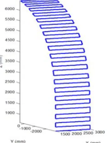
As described been installe conditions of fore and afterFigure 7 Ren nel using the
The purpose control syste sition and or sian coordina O0 (see Fig. profile. After the raw scanner a po rendered to cloud of poi tunnel with a it is possible Even though information, not smooth e vector. When design profil normal to ea sign of the tu that intersect
given mix and ers (concrete f it is the main evaluating th hese parameter guarantee a fa d on a data log transmission rameters with es per second
LADAR
y generati
d before, in the ed in order to f the working r the shotcreti
ndered image e LIDAC – 16
of the first s em with the de rientation of th ates according 2) in order t
w cloud of poin olyhedral mes
a continuous ints is proces a reasonable s e to evaluate h the geometry
sometimes th enough for ext n this occurs le of the tunn ach point quit unnel profile i t between each
d therefore to r flow) accordin control system he properties o
rs.
ast rate of acq gger and it use as it is necess h a rate of tr
d but not the
scanner
ion
e machine a L o acquire the area by scann ing process.
of the scanne by AITEMIN
scan is to pro etailed inform he surface of g to the origin to generate a
nts is availabl sh can be fitte s surface (see
sed and filter size, complex the proper s y can evaluate he representati tracting a true a proper solu nel, which al te straightforw is usually mad
h other.
regulate the p ngly [8][9].
m the one tha of the concret
quisition, the es the USB con
sary to monito ransmission (u e complete ra
and traj
LADAR scann information ning the surfa
ed surface of a N.
ovide the auto mation about th
the tunnel in n of the manip
shotcrete traj
le from the LA ed into it, and e Fig. 7). On
red to represe xity and smoo shotcrete traje ed from the sc ion of the surf e or sensible n ution is to app llows assignin wardly [8]. Th de from tangen
pump-at it is te ac- inter- nnec-or the up to ate is
jec-ner has of the ace be-a tun-omated he po- Carte-pulator ectory ADAR d then ce the ent the othness ectory. canned face is normal ply the ng the his de-nt arcs The conti param conv form Figu on th The The that tion; made ally are d poin may cord The d/nd direc omet get p The tatio tunn has t sition face. This time time of ar the j ing t
trajectory gen inues by eval meters and th venient trajec m.
ure 8 Example he geometry o
initial parame P0: Initial w: Width
tion. d: distan nw: Numb
tory a nd: Numb throug
sequence star it should be th w is the wid e in each pace from 1.5 to 2m defined nw poi
t would be de be modified ing to the scan same sequenc distance. This ction but the try of the tunn point the orien
trajectory gen n of the targe el has a vert to be evaluate ns for all the .
is why the im for the inver needed to ge round 900 targ joints by inve time to the m
neration starts luating a path he shape of th ctory should
e of a desired of a tunnel.
eters are: l target positio h of each line o
nce between lin ber of points f according to it ber of points i gh its high (us
rts when the o he closer poin dth of the adv e of the tunne m); this mean ints to from a efined at a w/n in y direction nned points. ce used to find
s distance is n perimeter of nel. It is impli ntation is inclu neration proce et point accord tical orientatio ed for each tar
joint is sent
mportance of t rse kinematic enerate the co get points and erse kinematic manipulator’s
by defining i h according t he tunnel. Usu
follow a sq
shotcrete traje
on of the traje of the trajecto
nes of the traj for each line o ts width. in each line of sually nw= nh)
operator select nt to the mach vancement tha el construction ns that if in x
line of sprayi nw distance. T n adapting eac
d target points not necessarily
the arc defin icit the fact th uded. ess finishes w
ding to the ge on. The inver rget point and to the manip
the optimisati evaluation. In omplete shotc d evaluate the p
cs, including t interface, go
its shape and i to some initia ually the mos quared shape
ectory based
ectory. ory in x
direc-ectory. of the
trajec-f the trajectory ).
ts the initial P hine in x direc at it should b n process (usu direction ther ing each targe he target poin ch position ac
s vertically at y the high in ned by the ge hat in each tar
when the orien eometry of th rse kinematic d the set of po pulator’s inter
ion the proces n this case th crete trajectory
position for al the download es from 15 to
20s, which fr is fair to say
4
Rea
tion
The control has been des the velocity trajectories) time (see Fig Such propert ternatives (e. ment, for the of the manip the homogen evaluating d the manipula
Figure 9 Blo creting proce
The thicknes the semi emp
where r(t) is F(t) is the ins concrete pum maining fact mix design,
) , (r K α
Ψ is
that represen sprayed conc the equation: r r Ψ Ψ , ( , ( α α The distance the effect of pendicular to rors caused b in the parame And finally G (Pm Th
from a real tun that it is a ver
al-time lay
n
system of the signed with th
of the coordin between the j g. 9).
ty may be us .g. a remote c e adjustment pulator during neity of the th different varia
ator control int
ock diagram fo ess.
ss of the shotc pirical equatio
the distance b stantaneous co mp, and M(·)
tors affecting rebound, nozz
a density fu nts the prob crete landing o : r if K G K = ⎜ ⎜ ⎝ ⎛ ⎜ ⎝ ⎛ − = 0 ) 1 1 ) α
e to the wall, c f the orientatio o the surface b by deformatio
eter K [8] Gα is defined b
∫
= 10
, (
) t 1
t
m M β β
nnel construct ry efficient pro
yer thick
e automated s he possibility o
nated movem joints of the
eful for remo control) or as of the velocit g spraying, in hickness of th ables provided
terface.
or high-quality
rete is estimat on [13]:
between the n oncrete flow g is a function g shotcreting zle attitude, w unction (in th bability of th on a different
K if K r > ⎟ ⎟ ⎠ ⎞ ⎟ ⎠ ⎞ ⎝ ⎛ α 2
compressed a on of nozzle w by the effects ons or backlas
by:
Ψ ( ) ( ...)
2 F t α r β
tion point of v ocess.
kness estim
shotcreting ma of the adjustm ments (used in manipulator i
ote teleoperati stated in this ty of the mov n order to ma he concrete lay
d by the pum
y automatic sh
ted at a point P
nozzle axis an given by mach
that models a performance wall position, e statistical s he volume o tial area define
K r≤
≤ ,
0
air flow and p when it is not
of the positio shes, are accou
) ), (t K dt r view it
ma-achine ment of linear in real ion al- docu-vement aintain yer by mp and
hot-Pm by
nd Pm, hine's all re-(e.g. etc.). sense) f the ed by art of t pon er-unted By m the a and o The parin ity. type, shotc chan etc.) That a sec of th layer autom justin
5
For wher struc5.1
The ing p pare Gmodifying α an actual sprayin
operating con spraying velo ng the type of
Usually the , or at least k crete operatio nical changes may comprom t it is why, aft cond scan of th his second sca
r. If the layer mated shotcre ng α and K fro
Experim
the validatio re made in a r ction purposes
Automat
first step was process based it to a manuaa.
∫
Ψ = K r G 0 2 α πnd K it is poss ng pattern of a nditions.
ocity is determ f concrete mix
construction known types, o
ons. But som on the machi mise the stated ter the shotcre he surface is m an is to verify r doesn’t matc eting paramet om the real tim
mental re
on of the sy real scale test s.
tic shotcret
to test the com on the geome al shotcreting cΨα(r,K)dr
sible to adjust any given ma
mined empiric x and the shotc
companies u of concrete m me circumstanc
inery, the use d velocity val eting process made. One of the quality of ch the require ters can be ch me thickness e
esults
ystem several facility for tu
ting proces
mplete autom etry of the tun carried out byb.
t the model to achine, nozzle
cally by com-creting veloc-use the same mixes for their ces (e.g. me-e of additivme-es,
ues.
is completed, f the meanings f the shotcrete ed quality, the hanged by ad-estimation.
experiments unnelling
con-s
mated shotcret-nnel and com-y an operator.
-Figure 10 Sh shotcreting b Automatic sh
According to during vario notable the d maintained b b).
The operator manipulator, tion of the no may lead to quently to th On the other matic sprayin tion and attitu There are im shotcrete tha on/off positio the hydraulic enough to m sired speed a ture. This ma this level of ess.
5.2
Thic
The estimati evaluated us crete process To test the stage the sur LADAR (see tion to evalua it is possible shotcrete proTable 2 Su
hotcreting traj b) Sample of a hotcreting ima
o the results g ous shotcrete differences be by the operato
r has to contro thus it is easi ozzle than the the radial a e semi-spheric r hand, it is als ng it is possib ude of the noz mprecise pos at are caused on control of c supply of th move all the j
and the mecha ay lead to pos precision is a
ckness estim
ion of the th sing the resul ses in a determfitness of the rface of the tu e Fig. 11). By ate the differe e to find the ocess.
ummary of sp
c.
ectory examp automatic shot age.
given by the m operations (s etween the atti or a) and the
ol independen ier for him to e rest of the jo attitude of the
cal geometry so noticeable ble to maintai zzle during th sitions encou mainly by th the prismatic he manipulato oints simultan anical deforma sitions errors o admissible for
mation
hickness of thlts of differen mined test area e estimation, unnel has been y using a comm
ences of the th amount of c
prayed volume
ples. a) Operat tcreting and c)
measurements see Figure 10 itudes of the n
automated p
ntly each joint move the las oints. This sit e boom and c
of the sprayin that with the in the correct e whole proce untered during he difficulty i
joint, the fac or is not pow neously at th ations of the s of up to 50mm r this kind of
he layer has nt automatic a.
in every spra n scanned wit mon squared hickness estim concrete used
e estimations [ tor’s )
s made 0) it is nozzle process of the st rota-tuation conse-ng. auto- posi-ess. g the in the ct that werful he de- struc-m, but proc-been shot-aying th the func-mation
d in a
[8].
Figu
imag It ca from the e uppe time estim the o more betw
6
Ther using the a manu also Neve desig pecte sion smoo the prop On t estim seve acco starti one t Fina carri autom nel c step botiz This for t proc costs prov operure 11 Differe ges [1].
n be noticed f m stage #1 dat
effect of wire er part of the
. For this rea mated volume
other hand, es e accurate and ween the measu
Conclu
re is a notable g robotization analysis of the ual and the a noticed on the ertheless, the gned for auto ed difficulties
of its movem othness of the shotcrete man portional contr
the other hand mation, deduc ral advantage ount the possib
ing mix or an to other jobsit lly and as a r ied out to me mation of the construction i in the implem ze heavier sho
may provide the developm
ess, which m s and quality ving the work rators inside th
ence between t
from Table 2 a seems less a e mesh and la
working are ason, and mo e are closer th stimations fro d the maximu ured and the e
sions and
e improvemen n techniques t e differences i automated pro
e real shotcret robotization mation purpo s. For examp ments are ade e trajectory m nipulator eno rols in all its jo d, the models ced from emp es like the fact ble variations ny other circum
te.
result of the d easure the diff e shotcrete pro industry, it is mentation of th otcrete machin
the industry w ent an unstru may lead to the
of the tunne king condition he construction
two successiv
that the volum accurate. This ack of scannin a before spra ost probably, han the measu om the stages um error of th estimated volu
d future w
nt in the qualit that are not o in the position ocess, but the ted surfaces.
of a machine oses usually p le, even thou equate for this may be improv ough hydrauli
oints. presented for pirical equati t that they do s caused by ch
mstances that
different expe ferent possibi ocess may off s planned to he method an nery.
with a standar uctured tunnel e optimisation el support lay
ns and the se n site.
ve 3D scanned
mes estimated s is caused by ng data in the aying for first the values of ured ones. On #2 and 3 are he differences ume is 5l.
work
ty of the layer only shown in n between the ey have been
e that it is not presents unex-ugh the preci-s procepreci-spreci-s, the ved by giving ic power and
the thickness ions, presents not take into hanges of the t change from
rimental tests ilities that the fer to the tun-take the next d use it to
7
Acknowledgements
The authors want to express their thanks to all AITEMIN and CSIC collaborators involved in the experimental pro-gram. Thanks are also extended to J.A. Nieto and M. Eck-stein of Putzmeister España for their support in the senso-rization of shotcreting machines; and to J.L. Rivas of SIKA España and his team, as well as to Fundación Santa Bárbara staff for their collaboration in the implementation of the experimental program. The work presented here was partially funded by the Spanish ministry of Science (Projects TUNPRO, BIA 2004-05562-C02-00, PIA12008-0 Ex.829370 and Project BOHEC, BIA2008-06673-C02-00/01/02)) and by the EU under the FP6 (TUNCONSTRUCT, IP-011817-2).
8
Literature
[1] Rodriguez A., O. Río, S. Nabulsi: Technology Inno-vation in Underground Construction. Chapter 19: "Real-Time Monitoring of the Shotcreting Process", Taylor and Francis 2009, pp: 373-388.
[2] Girmscheid, G., S. Moser: Fully Automated Shotcrete Robot for Rock Support. Computer-Aided Civil and Infrastructure Engineering 16, 2001 pp. 200-215 [3] Bracher, G.: CAS Computer Assisted Spraying of Wet
Process Sprayed Concrete, Tunel ROČNÍK, č. 2. 2003.
[4] Melbye, R. Dimmock, K.F. Garshol: Sprayed concrete for rock support 9th Edition Degussa-MBT, Winter-thur, Swiss. 2001.
[5] Putzmeister Iberica S.A. 2009
http://shotcrete.putzmeister.es/pm407i.html
[6] Denavit, J. and R.S. Hartenberg: A kinematic notation for lower-pair mechanisms based on matrices, Trans ASME J. Appl. Mech, 23:215-221, 1955.
[7] Spong, M. and M. Vidyasagar, Robot Dynamics and Control, Wiley, New York, 1989.
[8] Rodriguez A., S. Nabulsi, O. Río: A method for esti-mating thickness of sprayed concrete layers from pumped volume. EURO-TUN 2009: Computational methods in tunneling, Bochum, September 2009, Vol II, pp: 875-881.
![Figure 1 Sika®-Putzmeister PM-407 [5].](https://thumb-us.123doks.com/thumbv2/123dok_es/6732692.827251/1.892.492.781.535.768/figure-sika-putzmeister-pm.webp)