Photoelectrochemical reactors for CO2 utilization
Sergio Castro*, Jonathan Albo and Angel Irabien
Department of Chemical & Biomolecular Engineering, University of Cantabria, Avda. Los Castros s/n, 39005 Santander, Spain
*Corresponding author, email: sergio.castro@unican.es
ABSTRACT
The photoelectrochemical reduction of CO2 to renewable fuels and valuable chemicals
using solar energy is a research topic that has attracted great attention recently due to its potential to provide value added products under the sun, solving the issues related to global warming at the same time. This review covers the main research efforts made on the photoelectrochemical reduction of CO2. Particularly, the study focuses in the
configuration of the applied reactor, which is a topic scarcely explored in the literature. This includes the main materials used as photoelectrodes and their configuration in the photoelectrochemical reactor, which are discussed for technical uses. The review provides an overview of the state-of-the-art and aims to help in the development of enhanced photoelectroreactors for an efficient CO2 utilization.
KEYWORDS: Photoelectrocatalysis; CO2 reduction; reactor configurations;
photoelectrodes; climate change
INTRODUCTION
The reduction of fossil fuels and the growing emission of carbon dioxide (CO2) have
accelerated research activities to produce fuels and chemicals from wasted CO2 as a 3 4 5 6 7 8 9 10 11 12 13 14 15 16 17 18 19 20 21 22 23 24 25 26 27 28 29 30 31 32 33 34 35 36 37 38 39 40 41 42 43 44 45 46 47 48 49 50 51 52 53 54 55 56 57 58 59 60
carbon source. CO2 can be considered an unlimited, renewable and valuable carbon
source instead of a greenhouse gas emission. However, due to the chemical properties of CO2, its transformation requires a high level of energy since the bond dissociation energy
of C=O is ~750 kJ·mol−1, higher than other chemical bonds such as C−H (~430 kJ·mol−1) and C−C (~336 kJ·mol−1).1 Nowadays, there are several technologies able to chemically
reduce CO2 to value added products. Among them: thermochemical processes (i.e.
hydrogenation, reforming), mineralization, electrochemical reduction and photo/photoelectro-chemical reduction.2 Compared to thermochemical processes, mineralization processes present limitations that should be solved through further technological developments due to the low carbonation rates, high cost and energy penalties. It is also possible to dissociate CO2 and H2O by thermolysis at extremely high
temperatures. Electrochemical processes, however, permit to dissociate H2O or CO2 at
ambient conditions using electricity and has attracted worldwide interest due to their potential environmental and economic benefits.3 This technology not only offer a viable route to reuse CO2 but also an excellent alternative to store intermittent energy from
renewable sources in the form of chemical bonds.4, 5 When electrochemical reduction
integrates a light source, a photoelectrochemical device is obtained, which has attracted an intense progress in recent years.6, 7 In principle, such integration reduces the system capital cost and enables higher efficiency by reducing losses in transporting electricity to the electrolysis cell, eliminating current collectors and interconnections between devices. The operation of a photoelectrochemical (PEC) cell is inspired by natural photosynthesis in which carbohydrates are formed from CO2. The goal is to use excited electrons that are
generated when the semiconductor absorbs light to effect electrochemistry on a redox couple strategically chosen to produce the desired chemicals.8
3 4 5 6 7 8 9 10 11 12 13 14 15 16 17 18 19 20 21 22 23 24 25 26 27 28 29 30 31 32 33 34 35 36 37 38 39 40 41 42 43 44 45 46 47 48 49 50 51 52 53 54 55 56 57 58 59 60
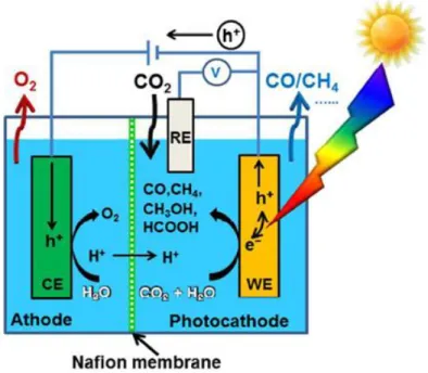
Figure 1. Photoelectrochemical setup.9
The concept of a photoelectrochemical cell is comparable to a conventional electrochemical cell, except that energy necessary to cause redox reactions is partially provide by the light. This concept is represented in Figure 1. A semiconductor material absorbs the light at the working electrode, exciting electrons to a higher energy level that, together with the corresponding holes generated, are able of carrying out reduction and oxidation reactions at a semiconductor/liquid interface. In practice, several characteristics of the photoelectrodes must be satisfied simultaneously: the electronic band gap of the photoelectrode must be low enough for efficient photon collecting from the solar spectrum (<2.2 eV) and high enough such that the excited electrons have enough energy to split water (>1.23 eV or typically at least 1.6–1.7 eV for sufficient rates), the band edges must cover the water electrolysis redox potentials and the photoelectrode must be stable and resistant to corrosion in the aqueous electrolyte.10 The photoelectrochemistry is therefore a thrilling and interdisciplinary research fied that includes electrochemistry, surface science, solid-state physics and optics.11
3 4 5 6 7 8 9 10 11 12 13 14 15 16 17 18 19 20 21 22 23 24 25 26 27 28 29 30 31 32 33 34 35 36 37 38 39 40 41 42 43 44 45 46 47 48 49 50 51 52 53 54 55 56 57 58 59 60
CO2 can be converted to a wide range of products such as CO, H2, HCOOH, CH3OH,
CH4, etc.12 Equations 1–5 shows the thermodynamic potentials for CO2 reduction
products at neutral pH in aqueous solution versus a saturated calomel electrode (SCE) and 25◦C and atmospheric pressure: 13
CO2 + 2H+ + 2e− → CO + H2O E ◦ = −0.77V (1) CO2 + 2H+ + 2e− → HCOOH E ◦ = −0.85V (2) CO2 + 6H+ + 6e− → CH3OH + H2O E ◦ = −0.62V (3) CO2 + 8H+ + 8e− → CH4 + 2H2O E ◦ = −0.48V (4) CO2 + e− → CO2•− E◦ = −2.14V (5)
The extent to which the reaction progresses depends mainly on the catalytic systems, as well as the reaction media and potential applied.12 Typically, multiple proton coupled electron transfer steps must be orchestrated, presenting kinetic barriers to the forward reaction.13 Besides, part of the energy supplied to the system may be consumed by the
competitive reaction for H2 production from water electrolysis in the Hydrogen Evolution
Reaction (HER). The state-of-the-art for the production of value added products from CO2 using solar energy is still far from practical consideration, but knowledge has been
accumulated through the years.14 Since the first report in 1978 on CO2
photoelectrochemical reduction by Halman, 15 many review articles have been writing about different aspects of this photoelectrochemical technology, as shown in Table 1. In 2014, Ibrahim et al.9 collected the available knowledge about photoelectrochemical
3 4 5 6 7 8 9 10 11 12 13 14 15 16 17 18 19 20 21 22 23 24 25 26 27 28 29 30 31 32 33 34 35 36 37 38 39 40 41 42 43 44 45 46 47 48 49 50 51 52 53 54 55 56 57 58 59 60
reactions to produce biofuel from biomass. In 2015, Sudha et al.16 review the recent
developments in the synthesis and application of composite photocatalysts derived from TiO2, CdS, WO3, SnS and ZnO. Moreover, Nikokavoura et al.17 presented alternative
photocatalysts to TiO2 for the photoelectroreduction of CO2. Inorganic and carbon based
semiconductors, mixed-metal oxides, salt composites and other groups of photocatalyst were examined in this review. Moreover, a simplified energetic and economic feasibility assessment for a solar refinery (including photoelectrochemical means) for the production of methanol was developed by Herron et al. 18, 19, concluding that at least a 15% solar-to-fuel efficiency is required in order to compete with industrial methanol production. Besides, one of the most important factors affecting the CO2 reduction performance is the
configuration of the photoreactor. A complete discussion on photoreactoreactor analysis and design was carry out by P.L. Yue in 1985.20 In this paper, the author presented and overview of the important engineering problems in the modelling and design of photoreactors. More recently, Cassano et al.21 in 2005, described the most important technical tools that are needed to design photoreactors using computer simulation of a rigorous mathematical description of the reactor performance, both in the laboratory and on a commercial scale.
Table 1. List of review articles on CO2 photoelectrochemical reduction.
Author (year) Publication title Ref.
A. J. Bard (1979) Photoelectrochemistry and heterogeneous
photo-catalysis at semiconductors 22 D.A. Tryk (2000) Recent topics in photoelectrochemistry:
achievements and future prospects 23 B. Kumar (2012) Photochemical and Photoelectrochemical
Reduction of CO2
13
A. Harriman (2013)
Prospects for conversion of solar energy into chemical fuels: the concept of a solar fuels
industry 7 3 4 5 6 7 8 9 10 11 12 13 14 15 16 17 18 19 20 21 22 23 24 25 26 27 28 29 30 31 32 33 34 35 36 37 38 39 40 41 42 43 44 45 46 47 48 49 50 51 52 53 54 55 56 57 58 59 60
S. N. Habisreutinger (2013) Photocatalytic reduction of CO2 on TiO2 and
other semiconductors 24 N. Ibrahim (2014) Biofuel from biomass via photo-electrochemical
reactions: An overview 9
J. Zhao (2014)
Hybrid catalysts for photoelectrochemical reduction of carbon dioxide: a prospective review on semiconductor/metal complex
co-catalyst systems
25
J. Highfield (2015)
Advances and Recent Trends in Heterogeneous Photo(Electro)-Catalysis for Solar Fuels and
Chemicals
26
Y. Yan (2015) Photoelectrocatalytic Reduction of Carbon
Dioxide 8
C. Ampelli (2015)
Electrolyte-less design of PEC cells for solar fuels: Prospects and open issues in the development of cells and related catalytic
electrodes
27
D. Sudha (2015) Review on the photocatalytic activity of various
composite catalysts 16
S. Xie (2016)
Photocatalytic and photoelectrocatalytic reduction of CO2 using heterogeneous catalysts
with controlled nanostructures
28
A. Nikokavoura (2017) Alternative photocatalysts to TiO2 for the photocatalytic reduction of CO2
17
L. Y. Ozer (2017)
Inorganic semiconductors-graphene composites in photo(electro)catalysis: Synthetic strategies,
interaction mechanisms and applications
29
P. Wang (2018) Recent Progress on Photo-Electrocatalytic
Reduction of Carbon Dioxide 30
In any case, it seems that the effect of reactor configuration in the CO2 photoreduction
performance has not been discussed in literature as much as the development of active materials. To fill this gap, the aim of the present review is to provide a deeper analysis on the photoelectroreduction of CO2 in terms of photoelectrochemical cell and
photoelectrodes configuration, together with a discussion on photoactive materials applied and obtained products for each configuration as key variables in process performance. The discussion is structured as follows: (i) Photoelectrochemical reactor
3 4 5 6 7 8 9 10 11 12 13 14 15 16 17 18 19 20 21 22 23 24 25 26 27 28 29 30 31 32 33 34 35 36 37 38 39 40 41 42 43 44 45 46 47 48 49 50 51 52 53 54 55 56 57 58 59 60
configurations, (ii) Photoelectrode materials, (iii) Main reduction products and finally, (iv) Conclusions and future challenges. This compilation aims to be a step further towards real application of photoelectroreactors for CO2 conversion.
SUMMARY OF STUDIES
PEC reactor configuration
The reactor can be considered the heart of a photoelectrochemical system. In a PEC reactor, the illumination of the photoactive surface becomes crucial, together with other common variables in reactors such as mass transfer, mixing or reaction kinetics. 31 The
design should be made based on a careful evaluation of different factors influencing reaction performance: 20, 21 (i) light source and geometrical configuration, (ii) construction material, (iii) heat exchange, (iv) mixing and flow characteristics and (v) phases involved and mode of operation.32 These are discussed as follows:
(i) For optimum results, light needs to be distributed homogenously through the entire photoactive surface.33 The choice of the most suitable light source can be made by
evaluating the reaction energy requirements with respect to the lamp specifications. The well-known Xenon arc lamp seems to be the most employed lamp in literature. This lamp produces a bright white light that closely mimics natural sunlight when electricity pass through the ionized Xe gas at high pressure.34, 35 If solar energy is being considered, it should be noticed that sunlight mainly consists of three different wavelengths: ultraviolet (λ < 400 nm), visible (λ = 400-800 nm) and infrared (λ > 800 nm), accounting for 4%, 53%, and 43% of the total solar energy, respectively.36 Moreover, it is recommended to give a certain pattern of irradiation by mounting the light source inside a glass sheath or some suitable optical assembly as Ampelli et al.37 evaluated where the Xe-arc lamp of
3 4 5 6 7 8 9 10 11 12 13 14 15 16 17 18 19 20 21 22 23 24 25 26 27 28 29 30 31 32 33 34 35 36 37 38 39 40 41 42 43 44 45 46 47 48 49 50 51 52 53 54 55 56 57 58 59 60
300 W was protected by a housing and a set of lenses were employed. Regarding geometrical configuration, it is necessary to determine the optical path of the light inside the reactor, in a way to obtain the maximum benefit from the irradiation pattern and a good absorption of light photons. For photo-reactors, other aspects such as the spatial relation between reactor and light source and geometry are crucial. In all cases, the irradiation takes place normal to the reactor surface.
(ii) In photo-reactors, the requirements of light transmission influenced in the construction material election. The choice is usually limited to different types of glass being the Pyrex glass the most used in the bibliography for its adequate light transmission and cost, 38-40 although quartz glass is more expensive, but generally gives the best performance in terms of light transmission. At short wavelengths (λ< 300 nm) quartz seems to be the only appropriate material. In some cases, the glass has been substituted by the plastic Plexiglas, except the reactor window, which continuous being made of glass to allow UV light transmittance. For instance, Cheng et al.41 reduced CO2 using a PEC
Plexiglas reactor with a quartz window achieving a light intensity at the anode surface of 10 mW·cm-2 with a 300 W Xe-arc lamp. Another important factor is the thickness of the
reactor wall, which decreases the light transmission and limited the size of the reactor and the operating temperature and pressure. Others authors,42, 43 use a different design to illuminate the photocatalyst surface, avoiding the problems of construction materials and light transmission by combining the PEC cell with a solar panel (PEC-photosolar cell tandem). Thus, the photomaterial is directly illuminated, the light is not disturbed by aqueous media and H2O could be oxidized in the photoanode without applying external
bias. 3 4 5 6 7 8 9 10 11 12 13 14 15 16 17 18 19 20 21 22 23 24 25 26 27 28 29 30 31 32 33 34 35 36 37 38 39 40 41 42 43 44 45 46 47 48 49 50 51 52 53 54 55 56 57 58 59 60
(iii) Heat exchange should be particularly considered, especially in gas-solid systems. Suitable devices must be designed to remove the heat generated by the lamp, because of the glass low thermal conductivity.32 For example, Ong et al.44 positioned a water jacket between the PEC cell systems and the Xe arc lamp to lessen the effects of heat on the Na2SO4 electrolyte solution during irradiation.
(iv) Mixing and flows depend on the phases involved in the process are also important factors to take into account. It is recommended to mix. In the case of heterogeneous photo- reactions, contact between reactants, photons and catalysts should be promoted, for example with agitation of the reacting mixture using a stirrer.32
(v) Photoreactors applied for CO2 photoconversion can be classified according to the
phases involved (i.e., gas-solid, liquid-solid, gas-liquid-solid, etc.) and the mode of operation (i.e., batch, semi-batch or continuous). Moreover, the materials can be generally in suspended (fluidized bed) or immobilized forms (fixed bed) in reactors. The main pros and cons of different current photoreactor systems for CO2 transformation are
summarized in Table 2.33 Figure 2 shows the schematic configuration of various types of photocatalytic reactors, which may serve as a reference for the design of new photoelectrocatalytic reactors (i.e. light incidence, flows inlet/outlet, photoactive surface configuration, etc.).
Table 2. Photoreactor systems: advantages and disadvantages.
Reactor design Advantages Disadvantages Ref.
Fluidized and slurry reactor
-Temperature
gradients inside the beds can be reduce
-Filters (liquid phase) and scrubbers (gas) are needed. 45-47 3 4 5 6 7 8 9 10 11 12 13 14 15 16 17 18 19 20 21 22 23 24 25 26 27 28 29 30 31 32 33 34 35 36 37 38 39 40 41 42 43 44 45 46 47 48 49 50 51 52 53 54 55 56 57 58 59 60
(multiphase) through vigorous movements caused by the solid passing through the fluids. -Heat and mass transfer increase due to agitated movement of solid particles. -High catalyst loading.
-Flooding tends to reduce the effectiveness of the catalyst.
-Difficulty of separating the catalyst from the reaction mixture.
-Low light utilization efficiency due to absorption and scattering of the light by the reaction medium. -Restricted processing capacities due to limitations in mass transfer.
Fixed bed reactor
-High surface area. -Fast reaction time. -The conversion rate per unit mass of the catalyst is high due to the flow regime close to plug flow.
-Low operating cost due to a reduced pressure drop.
-Temperature gradient between gas and solid surface. 48, 49 3 4 5 6 7 8 9 10 11 12 13 14 15 16 17 18 19 20 21 22 23 24 25 26 27 28 29 30 31 32 33 34 35 36 37 38 39 40 41 42 43 44 45 46 47 48 49 50 51 52 53 54 55 56 57 58 59 60
Monolith reactor
-High surface to volume ratio and low pressure drop with high flow rate.
-Configuration can be easily modified.
-Low light efficiency due to opacity of channels of the monolith. 50, 51 Optical fiber reactor
-High surface area and light utilization efficiency.
-Efficient processing capacities of the catalyst.
-Maximum use of the reactor volume is not achieved.
-Heat build-up of fibers can lead to rapid catalyst deactivation. 51, 52 3 4 5 6 7 8 9 10 11 12 13 14 15 16 17 18 19 20 21 22 23 24 25 26 27 28 29 30 31 32 33 34 35 36 37 38 39 40 41 42 43 44 45 46 47 48 49 50 51 52 53 54 55 56 57 58 59 60
Figure 2. (a) Monolith photoreactor,50 (b) Optical fiber photoreactor 51 and (c) Fixed bed photoreactor.45
The recirculation of unconverted CO2 also must be taken into account when designing an
effective photoelectroreactor, since the separation of the products from CO2 could
account for 6-17% of the total energy required in the process.53 Moreover, undivided photoelectrochemical reactors (Figure 3), in which plate-type electrodes are separated by a liquid phase that acts as both anolyte and catholyte have been commonly used. In these type of cells, the process costs increase due to the extra separation step required for the product recuperation.54 For a practical use of PEC cells, the separation in two distinct
3 4 5 6 7 8 9 10 11 12 13 14 15 16 17 18 19 20 21 22 23 24 25 26 27 28 29 30 31 32 33 34 35 36 37 38 39 40 41 42 43 44 45 46 47 48 49 50 51 52 53 54 55 56 57 58 59 60
compartments where CO2 reduction and water oxidation take place, is more appealing
than the single compartment process, since one can deal with one reaction at a time. As a result, the efficiency of the redox reactions increase, as so the charge recombination and products separation .37, 55, 56 The election between single and dual compartment cell does not follow a determinant rule and depends on the case, although dual compartment cells are usually preferred. 37, 38, 40
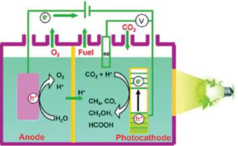
Besides, in order to allow an efficient collection/transport of electrons over the entire film as well as the diffusion of protons through the membrane (Figure 4), both anode and cathode should be in the form of a thin film separated by a proton-conducting membrane (Nafion or other materials)37, 57 and fixed onto a porous conductive substrate in the PEC cell. For CO2 photoreduction, an efficient evolution of oxygen on the anode side is also
needed, together with an efficient evolution of CO2 and diffusion of reaction products on
the cathode side. Moreover, the use of gas diffusion electrodes (GDEs) and gas phase operation on the cathode compartment is preferable, in order to avoid the limitations of CO2 solubility.37, 58 3 4 5 6 7 8 9 10 11 12 13 14 15 16 17 18 19 20 21 22 23 24 25 26 27 28 29 30 31 32 33 34 35 36 37 38 39 40 41 42 43 44 45 46 47 48 49 50 51 52 53 54 55 56 57 58 59 60
Figure 3. Single compartment cell (W= working electrode, R= reference electrode, and C=counter electrode).59
The mass transport in the electrode is a limiting factor as better catalyst are progressively becoming available. For this, several elements have been considered: high pressure operation, the use of GDEs and no aqueous electrolytes. 60 GDEs usually consists of a
carbon fiber substrate (CFS), a micro porous layer (MPL), typically is composed of carbon powder and polytetrafluoroethylene (PTFE), and a catalyst layer (CL). Del Castillo et al., 61 compared a Sn-GDE with a Sn plate electrode and obtained higher rates for the Sn-GDE than for Sn plate electrode, demonstrating the exceptional performance of GDEs for CO2 reduction. 60, 62 Gas phase CO2 transformation by using GDEs can be
also applied to enhance CO2 transfer, allowing the operation at higher current densities in
the cell as demonstrated by Merino-Garcia et al.,63 in a dual compartment cell for methane and ethylene production by using a Cu-based membrane electrode assembly (MEA).
Figure 4. Dual compartment cell.64
3 4 5 6 7 8 9 10 11 12 13 14 15 16 17 18 19 20 21 22 23 24 25 26 27 28 29 30 31 32 33 34 35 36 37 38 39 40 41 42 43 44 45 46 47 48 49 50 51 52 53 54 55 56 57 58 59 60
Moreover, the type of ion transport membrane applied is key in the CO2
photoelectrochemical reduction performance, where proton exchange membranes (PEMs) are preferred due to their favored protons transport from the anode to the cathode than the anion exchange membranes (AEMs), with anions transported from the cathode to the anode compartment, but of course it may depend on the reaction conditions and cell configuration. 54 The expected reactions in a PEM-based reactors are: 55
Cathode: CO2 + 2H+ + 2e− → CO + H2O (6) 2H+ + 2e- ↔ H 2 (7) Anode: 2H2O ↔ O2 + 4H+ + 4e- (8)
While the expected reactions in a AEM are: 55
Cathode:
3CO2 + H2O + 2e- ↔ CO + 2HCO3- (9)
2CO2 + 2H2O + 2e- ↔ H2 +2HCO3- (10)
Anode:
2HCO3- ↔ 1/2O2 + H2O + 2CO2 (11)
There are many examples on the use of PEMs in photoelectroreduction, 5, 65, 66 while AEMs are not usually employed, although some examples are reported in electrochemical devices where current densities as high as 130 mA·cm-2 can be achieved.67 This is the case for the new anion-conductive polystyrene methyl methylimidazolium chloride (tradenamed SustainionTM) AEM membrane developed by Masel and co-workers, which
3 4 5 6 7 8 9 10 11 12 13 14 15 16 17 18 19 20 21 22 23 24 25 26 27 28 29 30 31 32 33 34 35 36 37 38 39 40 41 42 43 44 45 46 47 48 49 50 51 52 53 54 55 56 57 58 59 60
excessed standards for product selectivity and current density with commercially available AEM. 67
Moreover, bipolar membranes (BPM), made of an anion and cation exchange membranes, have recently gain interest for CO2 transformation due to their ability to separate anode
and cathode compartments and the high sensitivity on pH required to facilitate different electrolyte conditions for the anode and for the cathode by the selective transport of OH -to the anode and H+ to the cathode. 68, 69 Maintaining the pH constant, BPMs allow the use of new earth-abundant metal anodes that are stable in basic conditions and highly active acid-stable cathodes for CO2 reduction, which cannot be realized by using PEMs
and AEMs 62 Recently, Zhou et al.,69 reported a FE >94% to HCOOH (8.5 mA·cm-2 ) using a GaAs/InGaP/TiO2/Ni photoanode and a Pd/C nanoparticle-coated Ti mesh
cathode, employing as electrolytes 1.0 M KOH (pH=13.7) and 2.8 M KHCO3 (aq)
(pH=8.0) separated by a BPM that facilitated the separation of redox reactions to achieve higher efficiencies and produce lower total overpotentials in comparison to a single compartment cell.
In addition, the formation of liquid products from CO2 reduction has mostly focused on
batch PEC reactors. 3, 4, 70, 71 Only a few researchers deal with the concept of continuous flow photoelectrochemical reactors, 72 required in the production at industrial scale, minimizing capital costs and maximizing product consistency as demonstrated in case of electrochemical systems for CO2 continuous reduction. To this end, a continuous flow
PEC reactor (CFPR) was developed in 2015 by Homayoni et al.73 to produce alcohols
from CO2 employing a CuO/Cu2O photocathode (Figure 5). The results show long-chain
alcohol products up to C2-C3 (ethanol and isopropanol) with a production rate of 0.22
ml·m-2·h-1, that was approximately 6 times higher than in a batch design.
3 4 5 6 7 8 9 10 11 12 13 14 15 16 17 18 19 20 21 22 23 24 25 26 27 28 29 30 31 32 33 34 35 36 37 38 39 40 41 42 43 44 45 46 47 48 49 50 51 52 53 54 55 56 57 58 59 60
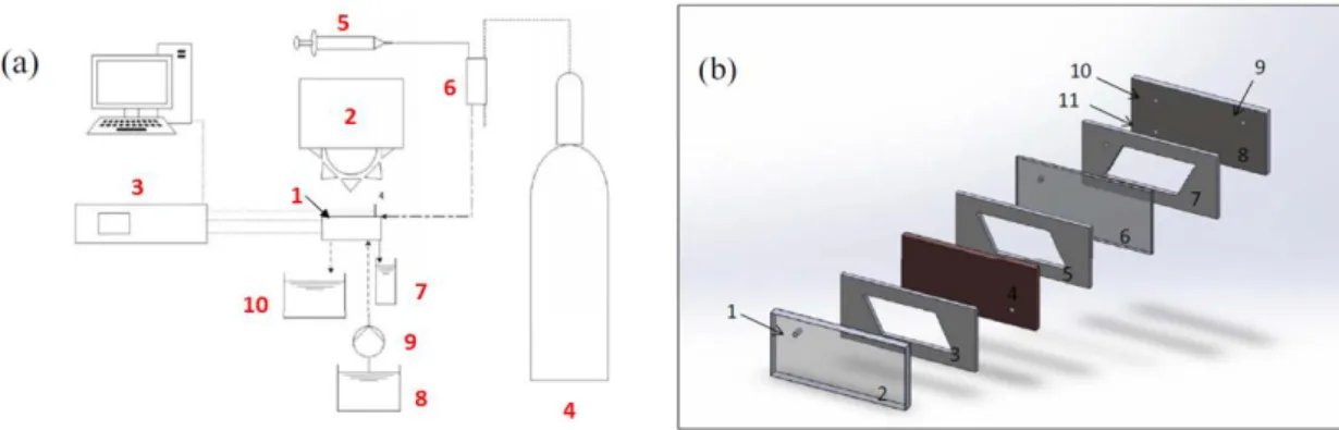
Figure 5. (a) Schematic diagram of the CFPR set-up: (1) CFPR, (2) solar simulator, (3) electrochemical workstation, (4) CO2 tank, (5) syringe pump, (6) fresh catholyte from
a gas mixing chamber, (7) catholyte collector, (8) fresh anolyte, (9) pump, and (10) anolyte collector. The electrical connections to the electrodes are marked as WE, CE and RE for the cathode, anode and reference electrode respectively. (b) Schematic diagram of the CFPR itself consisting of: (1) catholyte inlet and location of the reference electrode, (2) optical window (transparent slab), (3) microchannel arrays slab on top of the cathode, (4) cathode, (5) microchannel arrays underneath the cathode, (6) ion exchange membrane, (7) microchannel arrays on top of the anode, (8) anode, (9) outlet of anolyte, (10) outlet of catholyte, and (11) inlet of anolyte.73
Furthermore, there are different electrode configurations for the PEC systems on dependence on which electrode (i.e., anode, cathode, or both) acts as photoelectrode, 65 as described in the following subsections.
Photocathode-dark anode.
Most of the studies employed a photocathode made of a p-type semiconductor, with a high conduction band energy suitable for CO2 reduction, and an anode made of metal
(Figure 6).74, 75 The first study was reported by Halmann in 1978, where a p-GaP semiconductor was used as photocathode, carbon rod as counter electrode and a buffered
3 4 5 6 7 8 9 10 11 12 13 14 15 16 17 18 19 20 21 22 23 24 25 26 27 28 29 30 31 32 33 34 35 36 37 38 39 40 41 42 43 44 45 46 47 48 49 50 51 52 53 54 55 56 57 58 59 60
aqueous solution as electrolyte.15 A 6 mA·cm-2 current was detected when p-GaP was
illuminated with an Hg lamp and a voltage bias of -1 V vs. SCE was applied. HCOOH, HCHO and CH3OH were formed. More recently, this type of configuration was
implemented by Qin et al.76 using TiO2 as photocathode and an electrode of Pt as anode
to obtain HCOOH, HCHO and CH3OH as main products.
Figure 6. Semiconductor as photocathode.28
Unfortunately, the valence band in p-type semiconductors does not cover H2O oxidation
and a bias potential is required. Besides, these materials are usually expensive, toxic and unstable and two-electron compounds, such as CO and HCOOH, are usually obtained as it was demonstrated by Kaneco et al.77 when a metal-doped (Pb, Ag, Au, Pd, Cu and Ni)
p-InP photocathode and a Pt foil as counter electrode was applied at -2.5 V vs. SCE (-2.5
V vs. Ag/AgCl) potential. Overall, the efficiency of p-type semiconductor-based systems is low, and the improvement required in photocathode efficiency remains a challenge.
Photoanode-dark cathode.
The use of a n-type semiconductor (e.g., TiO2, ZnO, BiVO4 or WO3) which are
earth-abundant, cheap and stable as photoanode for H2O oxidation, and a metallic
electrocatalyst active for CO2 reduction as the cathode to assemble a photoanode-dark 3 4 5 6 7 8 9 10 11 12 13 14 15 16 17 18 19 20 21 22 23 24 25 26 27 28 29 30 31 32 33 34 35 36 37 38 39 40 41 42 43 44 45 46 47 48 49 50 51 52 53 54 55 56 57 58 59 60
cathode PEC reactor is also an attractive option (Figure 7). 41, 78 CO
2 reduction in a
photoanode-dark cathode PEC depends on two components: cathode catalysts and photoanode activity. This cell could improve CO2 reduction values obtained in
electrocatalytic systems and reduce energy input over the photoanode catalyst, requiring a lower external bias for an effective CO2 reduction than the photocathode-dark anode
configuration.28, 65 In this configuration, the photoanode plays a dual role during CO 2
reduction. On the one hand, the voltage generated by the light in the anode supply an extra negative potential to the cathode for CO2 reduction and on the other hand, protons and
electrons for CO2 reduction in the cathode were provided by the oxidation of water in the
anode.65 Chang and coworkers 79 used TiO2 as a model photoanode and Cu2O as a dark
cathode to devise a stable system for photoconversion with a FE of 87.4% and a selectivity of 92.6% for carbonaceous products from CO2. For instance, a Pt-modified
reduced graphene oxide (Pt-RGO) cathode and a Pt modified TiO2 nanotubes (Pt-TNT)
photoanode converted CO2 into HCOOH, CH3OH, CH3COOH and C2H5OH under
UV-Vis irradiation, applying a potential of 2 V.41 In further investigations, the cathode was substituted by Pt-RGO/Cu foam 78 and Pt-RGO/Ni foam 65 to improve products
selectivity.
Figure 7. Semiconductor as photoanode.28
3 4 5 6 7 8 9 10 11 12 13 14 15 16 17 18 19 20 21 22 23 24 25 26 27 28 29 30 31 32 33 34 35 36 37 38 39 40 41 42 43 44 45 46 47 48 49 50 51 52 53 54 55 56 57 58 59 60
Photocathode-photoanode.
Another option for the photoelectrodes in an assembly of PECs is the combination of a photocathode made of a p-type semiconductor for CO2 reduction with a photoanode made
of a n-type semiconductor for H2O oxidation (Figure 8). This configuration, in contrast
to the other two, allow realizing the transformation of CO2 with H2O without external
electrical energy. In this case, the conduction band edge of the photoanode for H2O
oxidation must be more negative than the valence band edge of the photocathode for CO2
reduction to guarantee the electron transfer from photoanode to photocathode through the external wire.28 Sato et al.38 employed this PEC configuration to produce HCOOH in a two-compartment Pyrex cell separated by a PEM using InP/[MCE]s and TiO2/Pt as
photocathode and photoanode respectively. By applying a light source, the two-compartment PEC cell could be run without external applied electrical energy. Not all the photocathode and a photoanode PECs cell configuration reported in literature are able to reduce CO2 without an external potential. Some need extra electrical energy to overcome
parasitic losses and reaction overpotentials, such as p-type Si nanowire/n-type TiO2
nanotube where traces of C3–C4 hydrocarbons, CH4 and C2H4 were formed under band
gap illumination and at 1.5 V vs. Ag/AgCl.80
Figure 8. Semiconductors as both photocathode and photoanode.28 3 4 5 6 7 8 9 10 11 12 13 14 15 16 17 18 19 20 21 22 23 24 25 26 27 28 29 30 31 32 33 34 35 36 37 38 39 40 41 42 43 44 45 46 47 48 49 50 51 52 53 54 55 56 57 58 59 60
PEC-solar cell tandem.
Traditionally, PEC cells and PV-electrolyzers are considered as different approaches, although some authors as Jacobsson et al.81 suggest than in many cases both approaches have certain similarities and should be considered under the acronym photo driven catalytic (PDC) devices. To be clear, a distinction should be made between the solar panel coupled in the photoanode 42 (PEC-solar cell tandem, Figure 9 ), and the photovoltaic
panels used as electric source to the PEC cell (PV-electrolyzers), which is the same as electroreduction using renewable energy. 43, 82, 83 In order to value the potential importance that can develop the PEC-solar cell tandem configuration in photoelectroreduction, the authors consider treating this configuration as one more added to the previous.
The main benefit of using a PEC cell (i.e. photocathode-anode, cathode-photoanode, photocathode-photoanode or PEC-solar cell tandem) than PV-electrolyzers is the possibility to deal with the generation of electrons required and the oxidation of H2O (if
a photoanode is employed) or adjust the redox potential to the interest product (if a photocathode is used) in the same device.
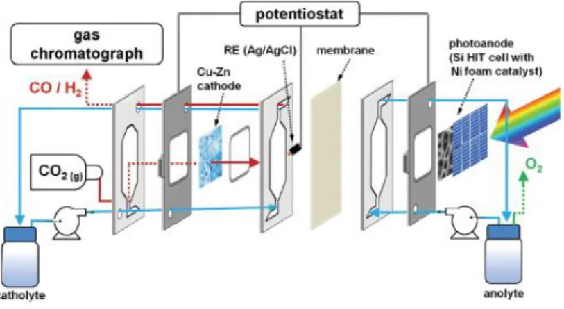
Figure 9. Filter-press reactor including a Cu-Zn cathode and a Si/Ni foam photoanode.42
3 4 5 6 7 8 9 10 11 12 13 14 15 16 17 18 19 20 21 22 23 24 25 26 27 28 29 30 31 32 33 34 35 36 37 38 39 40 41 42 43 44 45 46 47 48 49 50 51 52 53 54 55 56 57 58 59 60
Figure 9 is an example of a PEC-solar cell tandem. An experimental set-up using Si heterojunction solar cells in combination with Ni foam as photoanode and Zn coated Cu foam as cathode was applied, reaching CO FEs up to 85% at 0.12 V vs. SCE (0.8 V vs. RHE) with a CO current density of 39.4 mA·cm-2, the highest reported for a Zn catalyst at such low overpotential. This reactor concept enhances the solar CO2 conversion by the
use of the well-known and developed Si heterojunction technology, which is nontoxic, abundant and cheap technology and it is being used in the photovoltaic industry nowadays.42
Photoelectrode materials
The next section briefly discusses on the main photoactive materials applied in the different photoelectron-chemical reactor configurations for the reduction of CO2.24 The
two basic requirements for photoelectrode materials are optical response, to effectively absorb sunlight, and catalytic activity, required for the CO2 reduction and H2O oxidation
reactions. In order to satisfy these requirements, the processing of materials with enhanced performance characteristics need to include a high solar energy conversion efficiency, stability in aquatic environments and low cost.9 In addition, the particle size of the photoelectrode material has a considerable effect on CO2 photoreduction efficiency
due to changes in CO2 adsorption, available active surface area and transfer pathways for
charge carriers to reach its surface. The performance can be normally enhanced at smaller particle sizes, although the smaller the size is the more the boundary of the particles, which leads also to a lower activity. Furthermore, it has been proved that the best way to improve the activity of photo-materials is controlling the facets of the photocatalysts applied.84 3 4 5 6 7 8 9 10 11 12 13 14 15 16 17 18 19 20 21 22 23 24 25 26 27 28 29 30 31 32 33 34 35 36 37 38 39 40 41 42 43 44 45 46 47 48 49 50 51 52 53 54 55 56 57 58 59 60
Typically, photoelectrocatalysis in contrast to common electrodes used in electrocatalysis, employs semiconductor electrodes. In addition, graphene-based nano-catalyst and organometallic complexes are commonly applied.2 Semiconductor-based electrodes absorb light to generate electron-hole pairs. The holes generated at the photoanode, typically a n-type semiconductor, oxidize H2O to O2, while the electrons
photogenerated at the cathode, usually a p-type semiconductor, reduce the CO2 to
valuable products such as CO, HCOOH, CH3OH or hydrocarbons in the presence or
absence of a co-catalyst.28 TiO2, ZnO, CdS and SiC are the most employed inorganic
binary compounds as semiconductor materials.
TiO2 photoelectrodes
TiO2 is the most investigated semiconductor material for photocatalytic processes. It is a n-type semiconductor that possesses a wide band gap (3.0 eV) 8 and has been considered a cheaper and more environmental friendly material since the first report in 1979.85 TiO2
has three kind of polycrystalline phases: anatase, brookite and rutile 86 with different symmetries, slip directions, theoretical crystal densities, close stacking planes and available interstitial positions, altering also the defect distribution and density. As an example, Liu et al.87 studied the photocatalytic reduction of CO2 on three TiO2
nanocrystal polymorphs pretreated with helium and concluded that for TiO2 surfaces
engineered with defect sites, brookite provided the highest yield for CO and CH4,
followed by anatase and rutile, probably due to a lower formation energy of oxygen vacancies (VO) on brookite.
The literature shows that TiO2 has been tested for the photocatalytic reduction of CO2
under various structures, such as nanosheets, nanocrystals, nanotube arrays, nanorods,
3 4 5 6 7 8 9 10 11 12 13 14 15 16 17 18 19 20 21 22 23 24 25 26 27 28 29 30 31 32 33 34 35 36 37 38 39 40 41 42 43 44 45 46 47 48 49 50 51 52 53 54 55 56 57 58 59 60
carbon-TiO2 nanocomposites and mesoporous TiO2-based materials.88 Zhao et al.89
reviewed the effects of surface point defects in the production of solar fuels from CO2 photoreduction in H2O. In TiO2, oxygen vacancies, impurities, Ti interstitials, Ti
vacancies, and defects at interfaces are examples of point defects. The defective TiO2 materials show superior performance than pristine TiO2 for CO2 photoreduction,
probably due to an enhanced dissociative adsorption of CO2, an improved solar energy
absorption due to a change in the electronic band structure and a reduced charge recombination due to the presence of charge traps. Unfortunately, TiO2 mainly absorbs
UV radiation, 9 which is only a small part of solar radiation. Although progresses have been made with TiO2, it seems that different materials should be considered in order to
enhance the photocatalytic transformation of CO2 to useful products.
Alternative photocatalyst to TiO2
Apart from TiO2, other semiconductor-based photoelectrodes could be used. Figure 10
shows the band-gap positions of other semiconductor materials and the standard reduction potentials for CO2 reduction to different products.However, the photogenerated electrons
in the conduction band edge of all the candidate semiconductors do not have enough driving force to carry out the activation of CO2 to CO2∙−(-2.14 V vs. SCE), which defines
the efficiency for CO2 photoreduction.64 3 4 5 6 7 8 9 10 11 12 13 14 15 16 17 18 19 20 21 22 23 24 25 26 27 28 29 30 31 32 33 34 35 36 37 38 39 40 41 42 43 44 45 46 47 48 49 50 51 52 53 54 55 56 57 58 59 60
Figure 10. Conduction band (in red) and valence band (in blue) positions of some semiconductors and the redox potentials (vs. NHE) for CO2 reduction and water
splitting at pH= 0.64
Barton et al.90 presented a selective and efficient conversion of CO2 to CH3OH at a p-type
semiconductor electrode made of a narrow band single crystal p-GaP (111) in a pyridine solution. The current efficiency is 100% at -0.3 V vs. SCE. Recently, Yu et al.91 developed a novel material by depositing a conformal, ultrathin, amorphous TiO2 film by
low-temperature atomic layer deposition on top of black Si. A photocurrent density of 32.3 mA·cm−2 at an external potential of 0.87 V vs. SCE (1.48 V vs. RHE) in 1 M NaOH electrolyte could be achieved. ZnO , a n-type semiconductor with a wide band gap energy has been also tested as photocatalytic material due to its photo-luminescence properties (including good transparency and high electron mobility) that shows potential for scintillator applications.16 WO3 is also suitable and stable enough for sustained reduction
of CO2. A PEC system using WO3 as photoanode and Cu or Sn/SnOx as a cathode has
been shown to achieve reduction of CO2 at low bias potentials under visible light.92 Si is 3 4 5 6 7 8 9 10 11 12 13 14 15 16 17 18 19 20 21 22 23 24 25 26 27 28 29 30 31 32 33 34 35 36 37 38 39 40 41 42 43 44 45 46 47 48 49 50 51 52 53 54 55 56 57 58 59 60
also considered as a promising material due to its earth abundance, but a co-catalyst is required to enhance its CO2 reduction. Song and co-workers 93 employed a Si
photoelectrode with a nanoporous Au film as co-catalyst in a photocathode-dark anode configuration. Applying a light intensity of 100 mW·cm-2 a 91% FE to CO was achieved.
Doping the photocatalysts surface with a co-catalyst is another used procedure to achieve enhancements on both conversion efficiency and product selectivity.84 In many cases, combination of a photocathode with a co-catalyst able to activate CO2 molecules is
needed since p-type semiconductor photocathodes do not act as a true catalyst for the activation of CO2 molecules, but just as light harvesters to generate electrons and holes.
For this purpose, metal complexes have attracted much attention, where the interface interaction between the semiconductor and the complex plays a decisive factor in the electron transfer and thus the CO2 photoreduction efficiency.25,28 Besides, Huang et al. 66 employed Co
3O4 as the light harvester and Ru(bpy)2dppz as electron transfer mediator
and CO2 activator to obtain HCOOH as main product. The results show a 380-fold
increase in CO2 concentration on this hybrid interface than that on Co3O4/FTO. The CO2
conversion to HCOO- occurred at an onset potential of -0.7 V vs. SCE (-0.45 V vs. NHE) under photoelectrochemical conditions, 160 mV more positive than its thermodynamic redox potential. At -0.85 V vs. SCE (-0.60 V vs. NHE), the selectivity of the HCOO- yield
reached 99.95%, with a production of 110 μmol·cm-2·h-1 and a FE of 86%. HCOO- was obtained by Morikawa et al. 94 conjugating a p-InP:Zn photocathode with a Ru complex-polymer electrocatalyst [Ru(L–L)(CO)2]n, for CO2 transformation with a TiO2
photoanode for water oxidation. The conversion efficiency was 0.04%, which is closed to that value obtained in natural photosynthesis. Sahara et al. 95 reported the first example
of a molecular/ semiconductor photocatalyst hybrid-constructed PEC to transform CO2 3 4 5 6 7 8 9 10 11 12 13 14 15 16 17 18 19 20 21 22 23 24 25 26 27 28 29 30 31 32 33 34 35 36 37 38 39 40 41 42 43 44 45 46 47 48 49 50 51 52 53 54 55 56 57 58 59 60
under visible-light in the presence of water, using a Ru(II)-Re(I) photo-cathode and a CoOx/TaON photoanode.
Main reduction products
The most common products from the photoelectrochemical reduction of CO2 are
summarized hereafter. H2 is a side reaction in CO2 electroreduction, and so it is not
thoroughly discussed in the section.
Carbon monoxide
CO2 reduction to CO can be seen as the simplest route for CO2 conversion. CO is also an
intermediate product for the synthesis of other products, such as CH3OH and hydrocarbon
fuels.96 Petit and co-workers 97 proposed the reduction CO2 to CO in a photocathode-dark
anode configuration using two systems: p-GaAs/0.l M KClO4, H2O, Ni(cyclam)2+ and
p-GaP/0.1 M NaClO4, H2O, Ni(cyclam)2+, which assist a selective photo-reduction at -0.44
V vs. SCE (-0.2V vs. SHE) using an anode of Pt, separated from the working-electrode compartment by glass frits. Using a similar photocathode (p-GaAs)-dark anode (Pt) cell configuration as Petit and co-workers in a one compartment cell, Hirota et al. 98 reduced CO2 to CO photoelectrochemically in CO2 + CH3OH at high-pressure conditions (40
atm). P-InP and p-Si as photoelectrodes were tested at different applied potentials. For 50 mA·cm-2, p-InP required -1.1 V, p-GaAs -1.6 V and p-Si -1.8 V, demonstrating that CO2
can be converted to CO at more positive potentials than for a Cu under similar experimental conditions and without illumination. Moreover, Kumar and co-workers 99 using a one compartment cell configuration and a p-type H-Si photocathode with a Re(bipy-But)(CO)3Cl (bipy-But) 4,4′-di-tert-butyl-2,2′-bipyridine) electrocatalyst
achieved a 600 mV lower potential (FE= 97%) than with a Pt electrode. The photocathode
3 4 5 6 7 8 9 10 11 12 13 14 15 16 17 18 19 20 21 22 23 24 25 26 27 28 29 30 31 32 33 34 35 36 37 38 39 40 41 42 43 44 45 46 47 48 49 50 51 52 53 54 55 56 57 58 59 60
+ anode electrode configuration is usually employed to produce CO, since two-electron chemical products are commonly found over p-type semiconductors. More recently, Sahara et al. 95 generated CO using a dual photocathode-photoanode cell configuration with an external electrical (0.3 V) and chemical bias (0.10 V) in a hybrid photocathode of NiO-RuRe and a photoanode of CoOx/TaON. The work can be considered the first example of a molecular-semiconductor hybrid PEC cell using water to reduce CO2.
Different photoelectrodes, apart from those mentioned above, are also reported with good results such as p-type silicon nanowire with nitrogen-doped graphene quantum sheets (N-GQSs); 100 p-GaAs and p-InP; 101 CoSn(OH)6; 102 and NiO-RuRe.103 Figure 11 compares
the FEs reported in literature for CO for the different electrode configurations in the PEC: dark anode (PC+A), photoanode-dark cathode (PA+C) and photocathode-photoanode (PA+PC). The results seem to show an enhanced reaction performance for a PC+A configuration.
Figure 11. FEs for CO at different electrode configurations in PEC cells. 0 10 20 30 40 50 60 70 80 90 100 PC + A PA + C PA + PC PA + SC FE (% ) [35] [39] [42] [79] [92] [93] [97] [98] [99] [101] [104] [105] [106] 3 4 5 6 7 8 9 10 11 12 13 14 15 16 17 18 19 20 21 22 23 24 25 26 27 28 29 30 31 32 33 34 35 36 37 38 39 40 41 42 43 44 45 46 47 48 49 50 51 52 53 54 55 56 57 58 59 60
Formic Acid
Particular reference is made in the literature to the formation of HCOOH, this being a product for which there is a growing demand and which is currently made by processes that are neither straightforward nor environmentally friendly.12 Morikawa and co-workers94 successfully achieved the photoreduction of CO2 to HCOOH without applying
any electrical bias, employing a photocathode-photoanode configuration separated by a PEM membrane, using water as a proton source and electron donor by conjugating a InP/Ru-complex for CO2 reduction with a TiO2 photocatalyst for water oxidation.
HCOOH was generated continuously with a FE of > 75%. However, the TiO2 high band
gap critically reduce its excitation wavelength to the UV range. Jiang et al. 107 expanded the TiO2 optical absorption region from the UV absorption to the visible light region by
depositing Fe2O3 (Fe2O3/TiO2 NTs) with an onset wavelength of ~600 nm. The maximum
selectivity was 99.89% with a rate of HCOOH production of 74896.13 nmol·h-1·cm-2 under optimal conditions in a photocathode-dark anode dual chamber cell using Pt as counter electrode. Employing a similar photoelectroreactor configuration, Gu and co-workers 108 reduced CO
2 to HCOOH without the need for a co-catalyst at an unparalleled
underpotential. However, FE was limited due to the competitive reaction for H2 formation
(HER). In his work, a p-type Mg-doped CuFeO2 electrode was found to reduce CO2 to
HCOOH photoelectrochemically with a maximum conversion efficiency at -0.9 V vs. SCE using a LED source (470nm) in experiments of 8 to 24 hours. Shen and co-workers
109 reported in 2015 one of the highest yields to HCOOH. In this work, CO
2 was reduced
using a photocathode-dark anode configuration at Cu nanoparticles decorated with Co3O4
nanotube arrays achieving a selectivity of nearly 100% employing a single compartment cell. The production of HCOOH was as high as 6.75 mmol·L-1·cm-2 in 8 h of experimental
time. One year later, Huang et al. 66 improved the yield reported by Qi Shen and
co-3 4 5 6 7 8 9 10 11 12 13 14 15 16 17 18 19 20 21 22 23 24 25 26 27 28 29 30 31 32 33 34 35 36 37 38 39 40 41 42 43 44 45 46 47 48 49 50 51 52 53 54 55 56 57 58 59 60
workers employing also Co3O4 as the light harvester, and Ru(bpy)2dppz as the electron
transfer mediator and CO2 activator. The photoelectroreduction of CO2 to HCOOH has
been realized for 8 hours with an onset potential as low as -0.69 V vs. SCE (-0.45 V vs. NHE) and an anode made of graphite. At an applied potential of -0.84 V vs. SCE (-0.60 V vs. NHE), the selectivity for HCOOH reached 99.95%, with a FE of 86% and a production of 110 μmol·cm-2·h-1.
Figure 12. Photoelectrochemical flow cell scheme using a TiO2 photoanode.110
Nowadays, improvements in HCOOH formation continues with new strategies. Irtem and co-workers, continuing with their research line using Sn,110, 111 proposedtwo strategies:
concentration of solar light on the photoanode and adjustment of cathode area. At a voltage of 1.2 V and with a TiO2 photoanode and a Sn cathode, FEs of 40-65% for HCOO
-production were obtained, with energy efficiencies as high as 70% using a two-compartment cell divided (Figure 12). This study demonstrated that a stable photoanode optimized the system efficiency using a GDE as a cathode to enhance mass transfer and provide a wide photovoltage for O2 evolution reaction (OER). Besides, three PEC cell 3 4 5 6 7 8 9 10 11 12 13 14 15 16 17 18 19 20 21 22 23 24 25 26 27 28 29 30 31 32 33 34 35 36 37 38 39 40 41 42 43 44 45 46 47 48 49 50 51 52 53 54 55 56 57 58 59 60
electrode configurations can be found in literature for HCOOH production, where PC+A seems to be beneficial as it is observed for HCOOH production (Figure 13).
Figure 13. FEs for HCOOH at different electrode configurations in PEC cells.
Methanol
CH3OH as a key commodity has become an important part of our global economy.
Several articles deal with CH3OH production 115-117 since it may directly replace fossil
fuels without modifications of the actual energy distribution infrastructure.3, 96, 118 Moreover, CH3OH is used in paints, building blocks for plastics, and organic solvents,
among others.Ogura and Uchida 14 were one of the first reporting the formation of CH3OH by photoelectroreduction of CO2 using a n-TiO2 photoanode and a metal
complex-confined Pt cathode separated by a PEM and a 500 W Xe lamp. In their experiments, it was observed that the feasibility for CO2 reduction in a photocell
depended mainly on the anolyte pH. pH higher than 12 led to CH3OH formation in the
0 10 20 30 40 50 60 70 80 90 100 PC + A PA + C PA + PC PA + SC FE (%) [38] [41] [66] [92] [94] [101] [104] [108] [110] [112] [113] [114] 3 4 5 6 7 8 9 10 11 12 13 14 15 16 17 18 19 20 21 22 23 24 25 26 27 28 29 30 31 32 33 34 35 36 37 38 39 40 41 42 43 44 45 46 47 48 49 50 51 52 53 54 55 56 57 58 59 60
cathode , and O2 evolved at the photoanode. The photoreduction of CO2 only occurred at
a pH below 11 when applying external energy.
Yuan el al. 119 proposed the photoelectroreduction of CO2 using a Cu2O photocahode and
a graphite sheet as dark anode, obtaining a concentration and FE for CH3OH formation
of 1.41 mmol and 29.1%, respectively, after 1.5 h of operation at 1.5 V vs. SCE in a single compartment cell with an irradiation of 100 mW·cm-2 emitted from a Xe lamp. The formation rate of CH3OH was 23.5 µmol·cm-2·h-1. A higher rate for CH3OH (45 μmol·cm -2·h-1) was achieved in a light-driven two compartment reactor using Cu
2O/graphene/TiO2
nanotube array (TNA) heterostructures and Pt as working electrode and counter electrode, respectively by Li et al.40 An intensity of 100 mW·cm-2 was applied by a 300 W Xe arc
lamp with a UV cutoff filter. Similar materials, but with different structure and in a single compartment cell, were employed by Lee and co-workers, 120 enhancing FE and stability towards CH3OH production from CO2 using Cu2O nanowires photocathodes with a TiO2
-Cu+ shell. The FE after 2 h of operation improved from 23.6% for a Cu2O photocathode
to 56.5% for Cu2O with a TiO2-Cu+ shell mainly due to a lower resistance to charge
transfer and an increased CO2 adsorption. Recently, Yang et al. 121 compared the CH3OH
formation at different catalytic processes (PEC, photocatalysis, electrocatalysis) on a SnO2 NRs/Fe2O3 NTs photocathode and a Pt wire anode employing a single compartment
cell. The largest CH3OH production (2.05 mmol·L-1·cm-2), obtained under visible light
(1.1 V extra) was far higher than that individually electro-or-photo-catalytic reduction. As it is the case for CO and HCOOH, the production of CH3OH can be enhanced with a
PC+A configuration (Figure 14). The extraordinary high FE obtained for CH3OH
formation (i.e. >100%) for PA+C system using TiO2 as photoanode and Pt as cathode,14
has been removed for a clear comparison.
3 4 5 6 7 8 9 10 11 12 13 14 15 16 17 18 19 20 21 22 23 24 25 26 27 28 29 30 31 32 33 34 35 36 37 38 39 40 41 42 43 44 45 46 47 48 49 50 51 52 53 54 55 56 57 58 59 60
Figure 14. FEs for CH3OH at different electrode configurations in PEC cells.
Methane
Kaneco et al. 104 demonstrated that the selectivity for the photoelectrochemical reduction of CO2 can be tuned by adding metal particles into the catholyte to form CH4 in a dual
compartment cell by adding Cu particles suspended CH3OH using a p-InP and a Pt foil
as photocathode and anode, respectively. A maximum FE for CH4 of 0.56% was achieved
at 265K under a 5000 W Xe lamp. In order to enhance the CH4 production efficiency,
Wang and co-workers 88 presented the use of ordered mesoporous TiO2 as photocathode
and Pt as anode for CO2 reduction to CH4. The ordered mesoporous TiO2 exhibits a higher
and stable production efficiency for CH4 (0.192 μmol·gcatalyst−1·h-1) which is 71 and 53
times higher than that for a commercial TiO2 (P25) and disordered mesoporous TiO2,
respectively. Employing a photoanode-dark cathode electrode configuration in a dual cell compartment, a FE of 67% for CH4 at -1.39 V vs. SCE (-0.75 V vs. RHE) and 71.6% for
all carbon-containing products at -1.34 V vs. SCE (-0.65 V vs. RHE) was achieved by
0 10 20 30 40 50 60 70 80 90 100 PC + A PA + C PA + PC PA + SC FE (% ) [41] [73] [79] [90] [114] [116] [120] [122] 3 4 5 6 7 8 9 10 11 12 13 14 15 16 17 18 19 20 21 22 23 24 25 26 27 28 29 30 31 32 33 34 35 36 37 38 39 40 41 42 43 44 45 46 47 48 49 50 51 52 53 54 55 56 57 58 59 60
Magesh et al. 92 using Cu as a cathode electrocatalyst and WO
3 as photoanode under bias
potential. Moreover, in a photocathode-dark anode electrode configuration, Ong and co-workers 44 reached 2.923 μmol·gcatalyst-1·h-1 of CH4 under visible light irradiation
employing a carbon nanodot/g-C3N4 (CND/pCN) hybrid heterojunction photocatalyst
with a mass loadings of 3% of CNDs and a Pt foil as anode. This improved in 3.6 times the CH4 generated with pCN pure. Thompson et al, 123 reported an initial conversion rate
of 2596 µL·gcatalyst-1·h-1 of CH4, the highest reported to date, employing Cu as cathode
and TiO2 as photoanode without using an external wire. Only UV light as an energy
source was employed to reduce CO2. In any case, FEs to CH4 are rarely reported with
values ranging from 54.6 to 67 % for a PA+C configuration.79, 92
Long chain hydrocarbons.
Attending to thermodynamics, CO2 reduction to long chain hydrocarbons is more
challenging because of the number of electron required.4 For instance, CO2 reduction to
CH3OH requires 6-electron process, while CO2 reduction to isopropanol is a 18-electron
reduction. These liquid fuels have higher energy densities and are more convenient for transport and storing. Ampelli et al. 37, 124 reduced CO2 to liquid fuels (mainly
CH3CH(OH)CH3) employing carbon-nanotube based electrodes, Pt/CNT and Fe/CNT
and nanostructured TiO2 as photoanode in a homemade Plexiglas-quartz window PEC
reactor, reaching a production of 2.28.10-2·µmol·h-1·cm-2 of CH3CH(OH)CH3 for the
Fe/CNT cathode. As it can see in Figure 15, better results were achieved when instead of Fe-CNT, Fe-nitrogen-doped carbon nanotubes were employed (5.74.10-2 µmol·h-1·cm-2). 3 4 5 6 7 8 9 10 11 12 13 14 15 16 17 18 19 20 21 22 23 24 25 26 27 28 29 30 31 32 33 34 35 36 37 38 39 40 41 42 43 44 45 46 47 48 49 50 51 52 53 54 55 56 57 58 59 60
Figure 15. Electroreduction of CO2 in the gas phase over Nafion® 117/Pt or
Fe(10%)/CNT)20%/carbon GDEs.124
Genovese et al.57 employed the same material but operated under a gas-phase electrocatalytic cell using electrodes based on metal nanoparticles supported and TiO2 as
photo-anode. Long C-chain products (i.e. CH3CH(OH)CH3 and C8-C9) were obtained
from CO2. Employing also a TiO2 photoanode and a nanostructured Pt/graphene aerogel
deposited onto a Cu foam (Pt/GA/CF), Zhang and co-workers 114 revealed that the Pt/GA/CF electrode improved CO2 reduction significantly and facilitated the conversion
of C1 to high-order products due to enhanced charge transportation. HCOOH, CH3COOH, C2H5COOH, CH3OH, C2H5OH were the main products detected. Recently,
Yuan et al. 125 showed is his study an outstanding performance for C
2H5OH production.
At the Cu2O foam cathode, the solar driven conversion of CO2 to C2H5OH led to a
formation rate as high as 71.67 μmol·cm-2·h-1 at only 131 mV within 1.5 h. There are a variety of FEs reported for different hydrocarbons, with values ranging from 32.6 to 52% for PC+A configurations 59, 73 and 2.7 for 45% to PA+C configurations.41, 92, 114
3 4 5 6 7 8 9 10 11 12 13 14 15 16 17 18 19 20 21 22 23 24 25 26 27 28 29 30 31 32 33 34 35 36 37 38 39 40 41 42 43 44 45 46 47 48 49 50 51 52 53 54 55 56 57 58 59 60
Finally, Tables 3, 4, 5 and 6 summarize the literature on the topic, paying special attention to the photoelectron-reactor/electrode configuration, but also including photoelectrocatalytic materials, main products obtained and process conditions.
3 4 5 6 7 8 9 10 11 12 13 14 15 16 17 18 19 20 21 22 23 24 25 26 27 28 29 30 31 32 33 34 35 36 37 38 39 40 41 42 43 44 45 46 47 48 49 50 51 52 53 54 55 56 57 58 59 60
37 Table 3. Experimental conditions and main products in a Photocathode-dark anode configuration.
Photocathode Anode Light source/
Intensity
Electrode Potencial
(V vs. SCE) Product FE/ Productivity Ref.
p-GaP Carbon road Hg-lamp
(λ=365 nm) -1 V CH2O HCOOH CH3OH - 15 p-GaAs Pt 150W Tungsten lamp (λ > 380 nm) -1.2 V CO 47% 97 p-Gap Pt -1 V CO 85% p-InP Pt 500 W Xe lamp (λ> 370 nm) -1.1 V CO 89%. 98 p-GaAs Pt -1.6 V CO 74%. p-Si Pt -1.8 V CO 75%. p-InP/deposited-metal [Pb,
Ag, Au, Pd, Cu and Ni] Pt
5000 W Xe lamp (λ> 300 nm) -2.5 V CO HCOOH - 77 p-GaAs Pt 5000 W Xe lamp (λ> 300 nm) −2.4 V CO HCOO -CO: 24.9% HCOO-: 14% 101 p-InP -2.5 V CO HCOO -CO: 41.5% HCOO-: 15%
ACS Paragon Plus Environment 3 4 5 6 7 8 9 10 11 12 13 14 15 16 17 18 19 20 21 22 23 24 25 26 27 28 29 30 31 32 33 34 35 36 37 38 39 40 41 42 43 44 45 46 47 48 49 50 51 52 53 54 55 56
38 p-GaP Pyridine 200 W Hg-Xe arc light (λ> 365 nm) -0.4 V CH3OH 88%-100% 90 p-InP Pt 5000 W Xe lamp (λ> 300 nm) -2.4 V to -2.8 V CO HCOOH CO at -2.7 V: 45.2% HCOOH at -2.6 V: 21.1% 104 p-Si Pt 150 quartz halogen lamp (λ<1000 nm) -0.6 V CO 97% 99 p-InP-Zn [Ru(L– L)(CO)2]n Xe light (400 nm <λ< 800 nm ) -0.6 V HCOO - 34.3 % 112 Cu2ZnSnS4 (CZTS) [RuCE + RuCA (400 nm <λ< 800 nm) -0.4 V HCOO - 82 % 113 meso-tetraphenylporphyrin
FeIII chloride at p-type Si CF3CH2OH
Halogen fibre optic lamp (λmax=
650 nm) -1.1 V CO 92% 39 Mg-doped CuFeO2 Pt 75 W Xe (350 nm<λ> 1350 nm) -0.9 V HCOO- 10% 108
ACS Paragon Plus Environment 3 4 5 6 7 8 9 10 11 12 13 14 15 16 17 18 19 20 21 22 23 24 25 26 27 28 29 30 31 32 33 34 35 36 37 38 39 40 41 42 43 44 45 46 47 48 49 50 51 52 53 54 55 56
39 Cu/Cu2O Pt 125 W Hg lamp 0.2 V CH3OH - 115 Cu/Cu2O Pt LED light (435 nm<λ> 450 nm) −2.0 V CH4 C2H4 C2H4: 32.69% 59
Wedged N-doped CuO Pt Xe lamp (λ≥ 420
nm) -1.2 V CH3OH 84.4% 116
Ordered mesoporous TiO2 Pt
300 W Xe arc lamp -0.4 V CH4 CO - 88 p-type CuO/Cu2O Stainless steel 378 (AM 1.5) Solar simulator (Newport Model 91160). -0.3 V C2H5OH C3H8O CH3OH C2H5OH:52% C3H8O:40% CH3OH:4% 59 Cu/Cu2O Pt 125 W Hg lamp 0.20 V CH3OH C2H5OH CH2O C2H4O CH3COCH3 - 117
Cu-Co3O4 NTs Pt 300 W Xe lamp -0.9 V HCOO- - 109
Cu2O-TiO2-x -
150 W Xe lamp
(AM 1.5) -0.07 V to -0.77 V
CH3OH
HCOOH - 34
NiO Pt LED with an
output of 1000 lm. -0.4 V H2 - 75
ACS Paragon Plus Environment 3 4 5 6 7 8 9 10 11 12 13 14 15 16 17 18 19 20 21 22 23 24 25 26 27 28 29 30 31 32 33 34 35 36 37 38 39 40 41 42 43 44 45 46 47 48 49 50 51 52 53 54 55 56
40 Ru(bpy)2dppz-Co3O4/CA graphite plate
Xe lamp (λ>420 nm) -0.84 V HCOO - 86% 66 1T@2H-MoS2 Pt Visible-light illumination (400nm <λ> 800 nm) -0.6 V - - 126 Au3Cu NP/Si NW - - -0.8 V CO - 127
Si Photoelectrode with the RA-Treated Au Thin Film
Mesh
- 100 mW cm−2 -0.73 V CO 91% 105
Cu2O/graphene/TNA Pt
300 W Xe Arc
lamp (λ>400 nm) -0.8 V vs. SCE CH3OH 45 μmol cm
-2 h-1 40 Ti/ZnO–Fe2O3 Pt 300 W Xe lamp(400 nm <λ< 800 nm) -0.5 V CH3OH HCOOH CH2O CH3OH: 0.773 mmol/cm2 74 Cu-ZnO/GaN/n+-p Si - 300 W Xe lamp -0.6 V CO 70% 35 Cu2O Pt LS 150 with AM1.5 G filter -0.3 V CH3OH 23.6% 120 Cu2O/TiO2 –Cu+ 50.7% CdSeTe NPs/TiO2 NTs Pt 500W Xe lamp (λ≥420 nm) -1.2 V CH3OH 88% 122 CdSeTe NSs/TiO2 CH3OH 25%
ACS Paragon Plus Environment 3 4 5 6 7 8 9 10 11 12 13 14 15 16 17 18 19 20 21 22 23 24 25 26 27 28 29 30 31 32 33 34 35 36 37 38 39 40 41 42 43 44 45 46 47 48 49 50 51 52 53 54 55 56
41 SnO2 NRs/Fe2O3 NTs Pt
Xenon lamp
(λ≥420 nm) -1.1 V CH3OH 87.04% 121
Cu2O Graphite sheet 100 mW cm-2 -0.6 V C2H5OH 0.071 mmol·cm-2·h-1 125
0D/2D CND/pCN Pt 300 W Xe arc lamp (λ> 400 nm) -0.5 V CH4 CO CH4: 2.9 μmol·gcatalyst−1·h-1 CO: 5.8 μmol·gcatalyst−1·h-1 44 Si/Au Graphite-rod 100 mW cm-2 0 V CO 96% 93
Table 4. Experimental conditions and main products in a Photoanode-dark cathode configuration.
Cathode Photoanode Light source/
Intensity
Electrode Potencial
(V vs. SCE) Product FE/ Productivity Ref.
Pt n-TiO2 500 W Xe-lamp -2 V CH3OH 100% 14 Pt-RGO Pt-TNT 300 W Xe-arc lamp -2 V C2H5OH CH3COOH CH3OH CH3OH: 5% HCOOH: 2.5% CH3COOH:20% 41
ACS Paragon Plus Environment 3 4 5 6 7 8 9 10 11 12 13 14 15 16 17 18 19 20 21 22 23 24 25 26 27 28 29 30 31 32 33 34 35 36 37 38 39 40 41 42 43 44 45 46 47 48 49 50 51 52 53 54 55 56
42 HCOOH C2H5OH:45% Cu WO3 500 W Hg lamp (λ > 420 nm) -1.39 V CO CH4 C2H4 CO: 0.6% CH4:67% C2H4:2.7% 92 Sn/SnOx -1.34 V CO HCOOH CO:15.9% HCOOH:27.5%
Pt-RGO/Cu TiO2 nanotube
300 W Xe-arc lamp (320 nm<λ>410 nm) -2 V HCOOH CH3COOH C2H5COOH CH3OH C2H5OH - 78 Pt-RGO Pt-TNT 300 W Xe arc lamp (320 nm<λ>410 nm) -2 V C2H5OH CH3COOH CH3OH HCOOH CO C2H5OH: 1350 nmol·cm-2·h-1 CH3COOH: 1150 nmol·cm-2·h-1 CH3OH: 875 nmol·cm-2·h-1 HCOOH: 820 nmol·cm-2·h-1 CO: 650 nmol·cm-2·h-1 128
ACS Paragon Plus Environment 3 4 5 6 7 8 9 10 11 12 13 14 15 16 17 18 19 20 21 22 23 24 25 26 27 28 29 30 31 32 33 34 35 36 37 38 39 40 41 42 43 44 45 46 47 48 49 50 51 52 53 54 55 56
43 Pt Cu-RGO-TiO2/ITO 150 W Xe arc lamp -0.61 V HCOOH CH3OH CH3OH: 255 mmol·cm-2·h-1 HCOOH: 189.06 mmol·cm-2·h-1 129 Pt-RGO Pt (5%)-TNT 300 W Xe arc lamp (320 nm<λ>410 nm) -2 V HCOOH CH3OH CH3COOH C2H5OH HCOOH: 80 nmol·cm-2·h-1 CH3OH: 75 nmol·cm-2·h-1 CH3COOH: 250 nmol·cm-2·h-1 C2H5OH: 280 nmol·cm-2·h-1 65 Cu2O TiO2 100 mW·cm-2 AM 1.5G -1.49 V CH4 CO CH3OH CH4: 54.63% CO:30.03% CH3OH:2.79% 79 Pt b-Si/TiO2/Co(OH )2 150W Xe lamp light 1.04 V - - 91 Pt/GA/CF TiO2 300 W Xe arc lamp (320 nm<λ>410 nm) -2 V HCOOH C3COOH C2H5COOH HCOOH: 19% CH3COOH: 24% C2H5COOH:23% 114
ACS Paragon Plus Environment 3 4 5 6 7 8 9 10 11 12 13 14 15 16 17 18 19 20 21 22 23 24 25 26 27 28 29 30 31 32 33 34 35 36 37 38 39 40 41 42 43 44 45 46 47 48 49 50 51 52 53 54 55 56
44 CH3OH C2H5OH CH3OH: 5% C2H5OH: 29% Sn-GDE TiO2 300 W Xe lamp -1.2 V HCOO - 40–65% 110 Cu TiO2NWs 250 W lamp (λ<400 nm) 0 V CH4 2596 µL·gcatalyst -1·h-1 123 Pd/C GaAs/InGaP/Ti O2/Ni 100 mW·cm -2 AM 1.5G 0 V HCOO- 94% 69 0
ACS Paragon Plus Environment 3 4 5 6 7 8 9 10 11 12 13 14 15 16 17 18 19 20 21 22 23 24 25 26 27 28 29 30 31 32 33 34 35 36 37 38 39 40 41 42 43 44 45 46 47 48 49 50 51 52 53 54 55 56
45 Table 5. Experimental conditions and main products in a Photocathode-Photoanode configuration.
Photocathode Photoanode Light source/Intensity Electrode Potential
(V vs. SCE) Product FE/ Productivity Ref.
InP/[MCE]s TiO2/Pt 1 sun (AM 1.5) 0 V HCOO
- 70%
38
p-type Si nanowire n-type TiO2
nanotube Photocathode:150W Xe lamp (AM 1.5) Photoanode: 25W Hg arc lamp -1.5 V CO CH4 C4H8 C2H4 C3H8 C4H10 CO: 824 nmol/cm2·h CH4: 121.5 nmol/cm2·h C2H4: 80 nmol/cm2·h 80
InP/Ru-complex TiO2 1 sun, Air Mass 1.5 0 V HCOO- 75% 94
Si NWs@CoP/CN TiO2
NWs@CoP/CN - -0.81 V
CO CH4
CO: 90% 106
NiO-RuRe CoOx/TaON
300 W Xe lamp (λ> 460
nm) -0.3 V
CO - 95
ACS Paragon Plus Environment 3 4 5 6 7 8 9 10 11 12 13 14 15 16 17 18 19 20 21 22 23 24 25 26 27 28 29 30 31 32 33 34 35 36 37 38 39 40 41 42 43 44 45 46 47 48 49 50 51 52 53 54 55 56
46 Table 6. Experimental conditions and main products in a PEC-Solar cell tandem configuration.
Photo/cathode Photo/anode Light source/Intensity Electrode Potential
(V vs. SCE) Product FE/ Productivity Ref.
ZnTe-Based Co-Ci 100 mW cm−2 0 V CO - 130
GaN Pt 300 W Xenon lamp - CH4 19 % 131
CuxO WO3
200 W Xenon lamp
(AM 1.5) 0 V
CO
HCOO- - 132
Cu-Zn Si/Ni 150 W Xenon lamp
AM 1.5 0 V
CO 85 % 42
ACS Paragon Plus Environment 3 4 5 6 7 8 9 10 11 12 13 14 15 16 17 18 19 20 21 22 23 24 25 26 27 28 29 30 31 32 33 34 35 36 37 38 39 40 41 42 43 44 45 46 47 48 49 50 51 52 53 54 55 56