DIPLOMADO DE PROFUNDIZACIÓN CISCO PRUEBA DE HABILIDADES PRÁCTICAS CCNP
JAIRO ALONSO GUEVARA MERA
UNIVERSIDAD NACIONAL ABIERTA Y A DISTANCIA – UNAD
ESCUELA DE CIENCIAS BÁSICAS, TECNOLOGÍA E INGENIERÍA – ECBTI INGENIERÍA DE TELECOMUNICACIONES
DIPLOMADO DE PROFUNDIZACIÓN CISCO PRUEBA DE HABILIDADES PRÁCTICAS CCNP
JAIRO ALONSO GUEVARA MERA
Diplomado de opción de grado presentado para optar el título de INGENIERO DE TELECOMUNICACIONES
DIRECTOR:
MSc. GERARDO GRANADOS ACUÑA
UNIVERSIDAD NACIONAL ABIERTA Y A DISTANCIA – UNAD
ESCUELA DE CIENCIAS BÁSICAS, TECNOLOGÍA E INGENIERÍA – ECBTI INGENIERÍA DE TELECOMUNICACIONES
3
NOTA DE ACEPTACIÓN
Firma del Presidente del Jurado
Firma del Jurado
Firma del Jurado
4
AGRADECIMIENTOS
Agradezco principalmente a Dios, por darme toda la fortaleza espiritual y por guiarme por un buen camino para así poder culminar esta etapa en mi vida.
5
CONTENIDO
AGRADECIMIENTOS ... 4
CONTENIDO ... 5
LISTA DE TABLAS ... 6
LISTA DE FIGURAS ... 7
RESUMEN... 8
ABSTRACT ... 8
INTRODUCCIÓN ... 9
DESARROLLO ... 10
1. Escenario 1 ... 10
2. Escenario 2 ... 22
CONCLUSIONES ... 36
6
LISTA DE TABLAS
7
LISTA DE FIGURAS
Figura 1. Escenario 1 ... 10
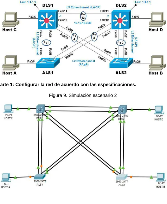
Figura 2. Simulación escenario 1 ... 10
Figura 3. Tabla de enrutamiento R1 ... 17
Figura 4. Tabla de enrutamiento R2 ... 18
Figura 5. Tabla de enrutamiento R3 ... 19
Figura 6. Ping desde R1 ... 20
Figura 7. Rutas filtradas ... 21
Figura 8. Escenario 2 ... 22
Figura 9. Simulación escenario 2 ... 22
Figura 10. VLAN en DLS1 ... 32
Figura 11. VLAN en DLS2 ... 32
Figura 12. VLAN en ALS1 ... 33
Figura 13. VLAN en ALS2 ... 33
Figura 14. EtherChannel en DLS1 ... 34
Figura 15. EtherChannel en ALS1 ... 34
Figura 16. Spanning tree en DLS1 ... 35
8 RESUMEN
En el siguiente trabajo, se realiza la actividad final del curso de profundización CISCO CCNP, en el cual se pone a prueba al estudiante mediante la solución de problemas relacionados con redes; aquí se abordan dos (2) escenarios propuestos, acompañado de los respectivos procesos de documentación de la solución, correspondientes al registro de la configuración de cada uno de los dispositivos, el registro de los procesos de verificación de conectividad mediante el uso de comandos ping, traceroute, show ip route y las respectivas evidencias de configuración de los dispositivos en el simulador Packet Tracer, las cuales dan veracidad del trabajo realizado.
Palabras clave: CISCO, CCNP, Redes, Ping, Traceroute.
ABSTRACT
In the following work, the final activity of the CISCO CCNP deepening course is carried out, in which the student is tested by solving problems related to networks; Here two (2) proposed scenarios are addressed, accompanied by the respective documentation processes of the solution, corresponding to the registration of the configuration of each of the devices, the registration of the connectivity verification processes through the use of ping commands, traceroute, show ip route and the respective evidence of configuration of the devices in the Packet Tracer simulator, which give veracity of the work done.
9
INTRODUCCIÓN
El curso de profundización CISCO CCNP, busca identificar el grado de desarrollo de competencias y habilidades que fueron adquiridas a lo largo del mismo. Lo esencial es poner a prueba los niveles de comprensión y solución de problemas relacionados con diversos aspectos de Networking.
10
DESARROLLO
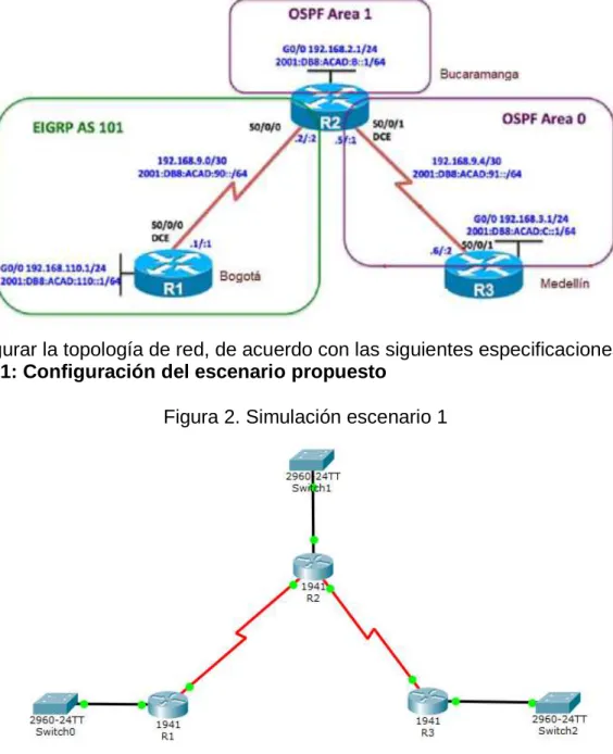
1. Escenario 1
Topología de red
Figura 1. Escenario 1
Configurar la topología de red, de acuerdo con las siguientes especificaciones. Parte 1: Configuración del escenario propuesto
11
1. Configurar las interfaces con las direcciones IPv4 e IPv6 que se muestran en la topología de red.
R1:
enable
configure terminal no ip domain-lookup hostname R1
ipv6 unicast-routing line console 0
logging synchronous exec-timeout 0 0 exit
interface g0/0
ip address 192.168.110.1 255.255.255.0 ipv6 address 2001:db8:acad:110::1/64 no shutdown
exit
interface s0/0/0
ip address 192.168.9.1 255.255.255.252 ipv6 address 2001:db8:acad:90::1/64 ipv6 address fe80::1 link-local
exit R2: enable configure terminal hostname R2 ipv6 unicast-routing no ip domain-lookup line console 0
logging synchronous exec-timeout 0 0 interface s0/0/0
ip address 192.168.9.2 255.255.255.252 ipv6 address 2001:db8:acad:90::2/64 ipv6 address fe80::2 link-local
no shutdown exit
interface s0/0/1
12 clock rate 128000
no shutdown exit
interface g0/0
ip address 192.168.2.1 255.255.255.0 ipv6 address 2001:db8:acad:b::1/64 no shutown exit R3: enable configure terminal hostname R3 ipv6 unicast-routing no ip domain-lookup line console 0
logging synchronous exec-timeout 0 0 exit
interface s0/0/1
ip address 192.168.9.6 255.255.255.252 ipv6 address 2001:db8:acad:91::2/64 ipv6 address fe80::3 link-local
no shutdown exit
interface g0/0
ip address 192.168.3.1 255.255.255.0 ipv6 address 2001:db8:acad:c::1/64 no shutdown
exit
2. Ajustar el ancho de banda a 128 kbps sobre cada uno de los enlaces seriales ubicados en R1, R2, y R3 y ajustar la velocidad de reloj de las conexiones de DCE según sea apropiado.
R1:
13 R2: interface s0/0/0 bandwidth 128 no shutdown exit interface s0/0/1 bandwidth 128 clock rate 128000 no shutdown exit R3: interface s0/0/1 bandwidth 128 no shutdown exit
3. En R2 y R3 configurar las familias de direcciones OSPFv3 para IPv4 e IPv6. Utilice el identificador de enrutamiento 2.2.2.2 en R2 y 3.3.3.3 en R3 para ambas familias de direcciones.
R2:
router ospfv3 1
address-family ipv4 unicast router-id 2.2.2.2
exit
address-family ipv6 unicast router-id 2.2.2.2
exit
R3:
router ospfv3 1
address-family ipv4 unicast router-id 3.3.3.3
passive-interface g0/0
default-information originate always exit
address-family ipv6 unicast router-id 3.3.3.3
passive-interface g0/0
14
4. En R2, configurar la interfaz F0/0 en el área 1 de OSPF y la conexión serial entre R2 y R3 en OSPF área 0.
R2:
interface g0/0
ospfv3 1 ipv4 area 1 ospfv3 1 ipv6 area 1 exit
interface s0/0/1 ospfv3 1 ipv4 area 0 ospfv3 1 ipv6 area 0 exit
5. En R3, configurar la interfaz F0/0 y la conexión serial entre R2 y R3 en OSPF área 0.
R3:
interface g0/0
ospfv3 1 ipv4 area 1 ospfv3 1 ipv6 area 1 exit
interface s0/0/1 ospfv3 1 ipv4 area 0 ospfv3 1 ipv6 area 0 exit
6. Configurar el área 1 como un área totalmente Stubby.
R2:
router ospfv3 1
address-family ipv4 unicast area 1 stub no-summary exit
address-family ipv6 unicast area 1 stub no-summary exit
15 R3:
router ospfv3 1
address-family ipv4 unicast
default-information originate always exit-address-family
address-family ipv6 unicast
default-information originate always exit
8. Realizar la configuración del protocolo EIGRP para IPv4 como IPv6. Configurar la interfaz F0/0 de R1 y la conexión entre R1 y R2 para EIGRP con el sistema autónomo 101. Asegúrese de que el resumen automático está desactivado.
R1:
router eigrp DUAL-STACK
address-family ipv4 unicast autonomous-system 101 interface g0/0
passive-interface exit
topology base exit
network 192.168.9.0 0.0.0.3 network 192.168.110.0 0.0.0.255 eigrp router-id 1.1.1.1
exit
address-family ipv6 unicast autonomous-system 101 interface g0/0
passive-interface exit
topology base exit
eigrp router-id 1.1.1.1 exit
9. Configurar las interfaces pasivas para EIGRP según sea apropiado.
R1:
int g0/0
passive-interface exit
16 R2:
router eigrp DUAL-STACK
address-family ipv4 unicast autonomous-system 101 topology base
distribute-list 1 out
distribute-list R3-to-R1 out
redistribute ospfv3 1 metric 1500 100 255 1 1500 exit-af-topology
address-family ipv6 unicast autonomous-system 101 topology base
redistribute ospf 1 metric 1500 100 255 1 1500 exit-af-topology
exit
11. En R2, de hacer publicidad de la ruta 192.168.3.0/24 a R1 mediante una lista de distribución y ACL.
R2:
access-list 1 deny 192.168.3.0 0.0.0.255 access-list 1 permit any
Parte 2: Verificar conectividad de red y control de la trayectoria.
17
18
19
20
b. Verificar comunicación entre routers mediante el comando ping y traceroute
21
c. Verificar que las rutas filtradas no están presentes en las tablas de enrutamiento de los routers correctas.
Figura 7. Rutas filtradas
Nota: Puede ser que Una o más direcciones no serán accesibles desde todos los routers después de la configuración final debido a la utilización de listas de
22 2. Escenario 2
Topología de red
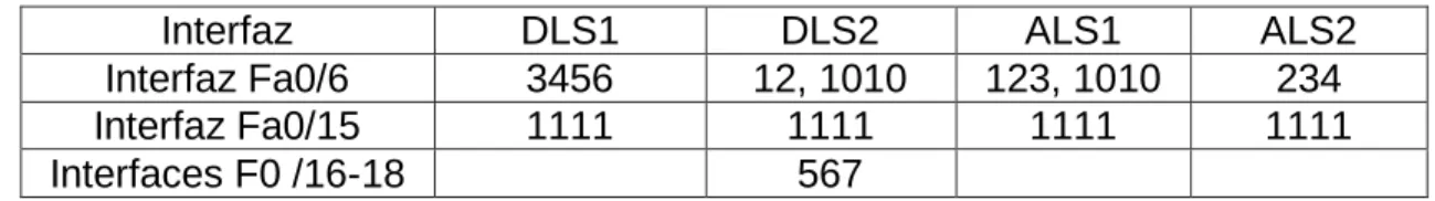
Figura 8. Escenario 2
Parte 1: Configurar la red de acuerdo con las especificaciones.
23
a. Apagar todas las interfaces en cada switch. DLS1:
Interface range f0/1-24, g0/1-2 shutdown
exit
DLS2:
interface range f0/1-24, g0/1-2 shutdown
exit
ALS1:
interface range f0/1-24, g0/1-2 shutdown
exit
ALS2:
interface range f0/1-24, g0/1-2 shutdown
exit
24
c. Configurar los puertos troncales y Port-channels tal como se muestra en el diagrama.
1) La conexión entre DLS1 y DLS2 será un EtherChannel capa-3 utilizando LACP. Para DLS1 se utilizará la dirección IP
10.12.12.1/30 y para DLS2 utilizará 10.12.12.2/30.
2) Los Port-channels en las interfaces Fa0/7 y Fa0/8 utilizarán LACP.
3) Los Port-channels en las interfaces F0/9 y fa0/10 utilizará PAgP.
4) Todos los puertos troncales serán asignados a la VLAN 800 como la VLAN nativa.
DLS1:
interface range f0/11-12 no switchport
channel-group 12 mode active no shutdown
exit
interface port-channel 12
ip address 10.12.12.1 255.255.255.252 exit
interface range f0/7-10
switchport trunk encapsulation dot1q switchport trunk native vlan 800 switchport mode trunk
switchport nonegotiate no shutdown
exit
interface range f0/7-8
desc member of po1 to ALS1 channel-group 1 mode active exit
interface range f0/9-10
desc member of po4 to ALS2 channel-group 4 mode desirable exit
DLS2:
interface range f0/11-12 no switchport
channel-group 12 mode active no shutdown
25 interface port-channel 12
ip address 10.12.12.2 255.255.255.252 exit
interface range f0/7-10
switchport trunk encapsulation dot1q switchport trunk native vlan 800 switchport mode trunk
switchport nonegotiate no shutdown
exit
interface range f0/7-8
desc member of po1 to ALS2 channel-group 2 mode active exit
interface range f0/9-10
desc member of po3 to ALS1 channel-group 3 mode desirable exit
ALS1:
interface range f0/7-10
switchport trunk native vlan 800 switchport mode trunk
switchport nonegotiate no shutdown
exit
interface range f0/7-8
desc member of po1 to DLS1 channel-group 1 mode active
switchport trunk allowed vlan 12,123,234,800,1010,1111,3456 no shutdown
exit
interface range f0/9-10
desc member of po 3 to DLS2 channel-group 3 mode desirable
switchport trunk allowed vlan 12,123,234,800,1010,1111,3456 no shutdown
exit
interface vlan 3456
ip address 10.34.56.101 255.255.255.0 no shutdown
exit
26 ALS2:
interface range f0/7-10
switchport trunk native vlan 800 switchport mode trunk
switchport nonegotiate exit
interface range f0/7-8
desc member of po2 to DLS2 channel-group 2 mode active
switchport trunk allowed vlan 12,123,234,800,1010,1111,3456 no shutdown
exit
interface range f0/9-10
desc member of po 4 to DLS1 channel-group 4 mode desirable
switchport trunk allowed vlan 12,123,234,800,1010,1111,3456 no shutdown
exit
interface vlan 3456
ip add 10.34.56.102 255.255.255.0 no shutdown
exit
ip default-gateway 10.34.56.254
d. Configurar DLS1, ALS1, y ALS2 para utilizar VTP versión 3
1) Utilizar el nombre de dominio UNAD con la contraseña cisco123
2) Configurar DLS1 como servidor principal para las VLAN. 3) Configurar ALS1 y ALS2 como clientes VTP.
DLS1:
vtp domain UNAD vtp version 3
vtp password cisco123 vtp primary vlan
ALS1:
vtp domain UNAD vtp version 3 vtp mode client
27 ALS2:
vtp domain UNAD vtp version 3 vtp mode client
vtp password cisco123
e. Configurar en el servidor principal las siguientes VLAN:
Tabla 1. VLAN
Número de VLAN Nombre de VLAN Número de VLAN Nombre de VLAN
800 NATIVA 434 ESTACIONAMIENTO
12 EJECUTIVOS 123 MANTENIMIENTO
234 HUESPEDES 1010 VOZ
1111 VIDEONET 3456 ADMINISTRACIÓN
28 f. En DLS1, suspender la VLAN 434.
DLS1:
vlan 434 state suspend exit
g. Configurar DLS2 en modo VTP transparente VTP utilizando VTP versión 2, y configurar en DLS2 las mismas VLAN que en DLS1.
DLS2:
vtp version 2
vtp mode transparent vlan 800 name NATIVA exit vlan 434 name ESTACIONAMIENTO exit vlan 12 name EJECUTIVOS exit vlan 123 name MANTENIMIENTO exit vlan 234 name HUESPEDES exit vlan 1010 name VOZ exit vlan 1111 name VIDEONET exit vlan 3456 name ADMINISTRACION
h. Suspender VLAN 434 en DLS2. DLS2:
29
i. En DLS2, crear VLAN 567 con el nombre de CONTABILIDAD. La VLAN de CONTABILIDAD no podrá estar disponible en cualquier otro Switch de la red.
DLS2:
vlan 567
name CONTABILIDAD exit
j. Configurar DLS1 como Spanning tree root para las VLAN 1, 12, 434, 800, 1010, 1111 y 3456 y como raíz secundaria para las VLAN 123 y 234. DLS1:
spanning-tree vlan 1,12,434,800,1010,1111,3456 root primary spanning-tree vlan 123,234 root secondary
k. Configurar DLS2 como Spanning tree root para las VLAN 123 y 234 y como una raíz secundaria para las VLAN 12, 434, 800, 1010, 1111 y 3456. DLS2:
spanning-tree vlan 123,234 root primary
spanning-tree vlan 1,12,434,800,1010,3456 root secondary
l. Configurar todos los puertos como troncales de tal forma que solamente las VLAN que se han creado se les permitirá circular a través de éstos puertos. DLS1:
interface port-channel 1
switchport trunk allowed vlan 12,123,234,800,1010,1111,3456 exit
interface port-channel 4
switchport trunk allowed vlan 12,123,234,800,1010,1111,3456
DLS2:
interface port-channel 2
switchport trunk allowed vlan 12,123,234,800,1010,1111,3456 exit
interface port-channel 3
30
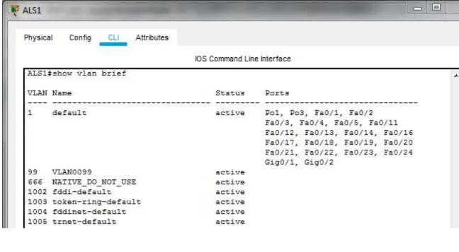
m. Configurar las siguientes interfaces como puertos de acceso, asignados a las VLAN de la siguiente manera:
Tabla 2. Configuración de Interfaces como puertos de acceso
Interfaz DLS1 DLS2 ALS1 ALS2
Interfaz Fa0/6 3456 12, 1010 123, 1010 234
Interfaz Fa0/15 1111 1111 1111 1111
Interfaces F0 /16-18 567
DLS1:
interface f0/6 switchport host
switchport access vlan 3456 no shutdown
exit
interface f0/15 switchport host
switchport access vlan 1111 no shutdown
exit
DLS2:
interface f0/6 switchport host
switchport access vlan 12 switchport voice vlan 1010 no shutdown
exit
interface f0/15 switchport host
switchport access vlan 1111 no shutdown
exit
interface range f0/16-18 switchport host
31 ALS1:
interface f0/6 switchport host
switchport access vlan 123 switchport voice vlan 1010 no shutdown
exit
interface f0/15 switchport host
switchport access vlan 1111 no shutdown
exit
ALS2:
interface f0/6 switchport host
switchport access vlan 234 no shutdown
exit
interface f0/15 switchport host
switchport access vlan 1111 no shutdown
32
Part 2: conectividad de red de prueba y las opciones configuradas. a. Verificar la existencia de las VLAN correctas en todos los switches y la
asignación de puertos troncales y de acceso
Figura 10. VLAN en DLS1
33
Figura 12. VLAN en ALS1
34
b. Verificar que el EtherChannel entre DLS1 y ALS1 está configurado correctamente
Figura 14. EtherChannel en DLS1
35
c. Verificar la configuración de Spanning tree entre DLS1 o DLS2 para cada VLAN.
Figura 16. Spanning tree en DLS1
36
CONCLUSIONES
Se logra configurar plataformas de conmutación basadas en switches, mediante el uso de protocolos como STP y la configuración de VLANs en escenarios de red corporativos, para comprender el modo de operación de las subredes y los beneficios de administrar dominios de broadcast independientes, en múltiples escenarios al interior de una red jerárquica convergente.
Se usa comandos IOS de configuración avanzada en routers (con direccionamiento IPv4 e IPv6) para protocolos de enrutamiento como: OSPFv3, EIGRP y BGP, en entornos de direccionamiento sin clase, con la intención de diseñar e implementar soluciones de redes escalables, mediante el uso de los principios de enrutamiento y conmutación de paquetes en ambientes LAN y WAN.
37
BIBLIOGRAFÍA
Teare, D., Vachon B., Graziani, R. (2015). CISCO Press (Ed). Basic Network and Routing Concepts. Implementing Cisco IP Routing (ROUTE) Foundation Learning Guide CCNP ROUTE 300-101. Recuperado de https://1drv.ms/b/s!AmIJYei-NT1IlnMfy2rhPZHwEoWx
Teare, D., Vachon B., Graziani, R. (2015). CISCO Press (Ed). EIGRP
Implementation. Implementing Cisco IP Routing (ROUTE) Foundation Learning Guide CCNP ROUTE 300-101. Recuperado de https://1drv.ms/b/s!AmIJYei-NT1IlnMfy2rhPZHwEoWx
Teare, D., Vachon B., Graziani, R. (2015). CISCO Press (Ed). OSPF
Implementation. Implementing Cisco IP Routing (ROUTE) Foundation Learning Guide CCNP ROUTE 300-101. Recuperado de https://1drv.ms/b/s!AmIJYei-NT1IlnMfy2rhPZHwEoWx
Teare, D., Vachon B., Graziani, R. (2015). CISCO Press (Ed). Manipulating Routing Updates. Implementing Cisco IP Routing (ROUTE) Foundation Learning Guide CCNP ROUTE 300-101. Recuperado de https://1drv.ms/b/s!AmIJYei-NT1IlnMfy2rhPZHwEoWx
Teare, D., Vachon B., Graziani, R. (2015). CISCO Press (Ed). Enterprise Internet Connectivity. Implementing Cisco IP Routing (ROUTE) Foundation Learning Guide CCNP ROUTE 300-101. Recuperado de
https://1drv.ms/b/s!AmIJYei-NT1IlnMfy2rhPZHwEoWx
Teare, D., Vachon B., Graziani, R. (2015). CISCO Press (Ed). Implementing a Border Gateway Protocol (BGP). Implementing Cisco IP Routing (ROUTE) Foundation Learning Guide CCNP ROUTE 300-101. Recuperado
de https://1drv.ms/b/s!AmIJYei-NT1IlnMfy2rhPZHwEoWx
Macfarlane, J. (2014). Network Routing Basics : Understanding IP Routing in Cisco Systems. Recuperado
de http://bibliotecavirtual.unad.edu.co:2048/login?url=http://search.ebscohost.com/l
38
Froom, R., Frahim, E. (2015). CISCO Press (Ed). Network Design Fundamentals. Implementing Cisco IP Switched Networks (SWITCH) Foundation Learning Guide CCNP SWITCH 300-115. Recuperado de
https://1drv.ms/b/s!AmIJYei-NT1IlnWR0hoMxgBNv1CJ
Hucaby, D. (2015). CISCO Press (Ed). CCNP Routing and Switching SWITCH 300-115 Official Cert Guide. Recuperado
de https://1drv.ms/b/s!AgIGg5JUgUBthF16RWCSsCZnfDo2
Donohue, D. (2017). CISCO Press (Ed). CCNP Quick Reference. Recuperado
de https://1drv.ms/b/s!AgIGg5JUgUBthFt77ehzL5qp0OKD
Froom, R., Frahim, E. (2015). CISCO Press (Ed). First Hop Redundancy Protocols. Implementing Cisco IP Switched Networks (SWITCH) Foundation Learning Guide CCNP SWITCH 300-115. Recuperado de
https://1drv.ms/b/s!AmIJYei-NT1IlnWR0hoMxgBNv1CJ
Froom, R., Frahim, E. (2015). CISCO Press (Ed). Network Management.
Implementing Cisco IP Switched Networks (SWITCH) Foundation Learning Guide CCNP SWITCH 300-115. Recuperado de
https://1drv.ms/b/s!AmIJYei-NT1IlnWR0hoMxgBNv1CJ
Froom, R., Frahim, E. (2015). CISCO Press (Ed). v. Implementing Cisco IP Switched Networks (SWITCH) Foundation Learning Guide CCNP SWITCH 300-115. Recuperado de https://1drv.ms/b/s!AmIJYei-NT1IlnWR0hoMxgBNv1CJ
Froom, R., Frahim, E. (2015). CISCO Press (Ed). Campus Network Security. Implementing Cisco IP Switched Networks (SWITCH) Foundation Learning Guide CCNP SWITCH 300-115. Recuperado de