Optimal Design of an Axially Displaced Ellipse
Myriam Tipán
Antenna
Germán V. Arévalo B. Galocha Iragüen
Abstract— Reflectors antennas in Ku band are primarily
used for satellite communications. They are mainly employed for establishing the communications for data transmission. In this paper, a displaced axis dual reflector antenna, usually referred as Axially Displaced Ellipse (ADE) antenna, is presented, demonstrating its advantages compared to the classical dual reflector antennas. Results show that the design antenna meets the expectations for SAT COM communications.
Keywords- ADE, reflector antenna, axially displaced ellipsoid
i. INTRODUCTION
The parabolic reflector antennas or dish antennas have been used far more widely in recent years with the high spread of satellite communications, the Axially Displaced Ellipse (ADE) antenna supposes an advantage from the constructive point of view by its compactness and high profit, that is why its use has extended. However, the dish antenna is used in many radio and wireless applications at frequencies usually above 1GHz where gains higher than 30 dBi are required along with narrow beam widths [1],
On one hand, the sophistication of the systems employed in Satellite Communications increases, so does their demand on the communication channel data rates required to relay the acquired information back to the earth. Therefore, increasing the antenna gain is an obvious choice. On the other hand, it is known that the gain of the antenna is directly proportional to its collecting area. Thus, the current trend is to obtain the maximum tolerable antenna aperture dimensions in small structures.
In this paper we use four geometric input parameters for fully defining the system, establishing a good starting point for an optimization process based on genetic algorithms. The antenna surfaces are synthetized with a ray tracing based algorithm, in order to define a function for field aperture and conforming the surfaces to meet the required illumination aperture.
The remaining of this paper has been organized as follows. Section II present the antenna parameters employed for its optimal design. Section III describes the antenna design process. In section IV the simulation and its results are presented and, finally, the conclusions are in section V.
ii. ANTENNA PARAMETERS
The antenna designed works at Ku band, the most important factor is to obtain high efficiency from a small aperture reflector, its gain must be over 30dBi and the cross polar ratio (XPR) in ±1° should be lower than -35dB. Other specifications to the reception link (RX) and transmission link (TX), like the sidelobe levels (SLL) are detailed in Table I.
This project began with the design of the reflective surfaces using geometric optics (ray tracing) to obtain conic parameters from the input parameters [2], The analytic expressions were programed in Matlab®. Several profiles for sub and main reflectors were obtained, by means of changing the optimization parameters.
We kept the feeder size smaller than the sub-reflector, in order to avoid blockage [3]. The feed was simulated in CST in order to get the co-polar and cross-polar pattern [4],
The feeder and the splash (sub reflector surface) were analyzed in the research reported in [5], Those results were used to illuminate the main reflector surface and evaluate the performance of the ADE with the reflector analysis program described in [6], taking into account the specific profiles and optics of our system.
TABLE I. ANTENNA SPECIFICATIONS
Parameter Frequency Polarization Antenna Gain Sidelobes template First SLL Characteristic RX 10.95 to 12.75 GHz Linear H/V TX 13.75 to 14.50 GHz Linear H/V 34.2+20*log(fi/13.75) dBi MIL-STD-188-164B
(3(6) = 32-25 loglO 6 (dBi), for 166 1/D ° < 6 < 48° (3(6) = -16 (dBi), for 48° < 6 < 186°
A6 1 ^18
III. ANTENNA DESIGN
The design parameters for the ADE are, the main reflector diameter (Dm), the focal distance of the main reflector (F), the
diameter of the subreflector (Ds), and the angle between the Z
axis and the ray emanating from the antenna's focus (F0) in
direction to the subreflector edge (9e). For The analysis of the
structure it was employed geometric optics (GO). The aim is to improve the efficiency and reduce the sidelobe levels.
•Xmr Ri
2I \>^ 1 % • Zmr
Ls —+•
The geometry of the antenna suggested in Fig.1 was selected for accomplishing all requirements specified in Table I. The main reflector is parabolic and the subreflector is a portion of an ellipse. In a Gregorian System, the rays emitted by the feeder are inverted, so that the lower portion of the subreflector reflects the incident rays to the upper section of the main reflector.
Calculus and procedure
• Main Reflector
The design of the antenna is for an application in Ku band. For calculating the frequency of work (Fwork) it was used
the frequency range from 10.95GHz (LF) to 14.5GHz (UF).
Fwork = ^LF-UF = 12.6GHz
X = c/Fwork = 3xl08 m/s /12.6 GHz = 0.0238
(1) (2)
The optimum point for having a good efficiency factor (εg ) is typically at an edge illumination (C) between -10,
-12 dB, so that (nt )parameter which is the relation among
spillover, blockage and aperture efficiency was chosen as 0.6, replacing all values of the parameters in the expression which relate the gain of the antenna (Gt ) and the area of
the reflector dish (A) the main reflector diameter was obtained. Gt= nt· (4 % A /?.2) A=7ir2 Dm=45.9cm = 46 cm (3) (4) (5) Subreflector
To calculate the dimension of the subreflector, based on reference [1], it was stablished that, to avoid excessive diffraction losses the subreflector diameter sould be at least 3 to 5 times the wavelenght. On the other hand for 99% blockage efficiency, the subreflector diameter should be 10 % to 15 % the main reflector diameter. So:
DS > 5^ DS =0.1Dm DS =0.1-46cm=4.6cm (6) (7) (8) Dm
Fig. 2. Substended angle of the main reflector.
• Feder
To design the horn, there are several models of radiating horns with low cross polarization over a large bandwidth. As feeder, a frontal choke horn with the next dimensions in terms of lambda, was chosen, [3]. The addition of one,
two and then three additional chokes, in cascade, could make possible to improve certain radioelectric characteristics (cross polarization, stability of frequency diagrams) while slightly increasing the directivity.
IV. SIMULATION AND RESULTS
An axial displaced elliptical reflector has been designed with a parabolic reflector as main surface and an ellipsoid as subreflector.
Fig. 3. One frontal choke horn.
In the first stage, an initial solution for main reflector, a paraboloid with circular rim of 460 mm diameter, was designed to verify if it could meet the electrical specification as well as the mechanical restrictions.
In the second stage are shown 2 designs, where the aperture was defined as hypo-elliptical type, with exponent 1.95 but the simulations were made with an elliptical opening, because, as detailed in [6], it will not support this contour [7]. A program that optimizes reflector surfaces is used, starting from the initial data. The program [5] generates a geometry for the sub-reflector and main reflector and obtains the spherical modes produced by the horn and subreflector. Then the program takes these results from [6] and obtain the directivity in Ku band frequencies and the side lobe levels, all this defining a target value.
First Stage: Complete System Optimization
Different cases were running, varying the limits of the optimization parameters.
Optimization process is performed as follows:
1) Definition of optimization function: Gain and SLL at lower and upper frequencies have been used to define the goal function, with different weights for each of them, according to design requirements.
2) Definition of optimization parameters: In this case, optimization parameters are:
a) Subreflector diameter b) Subreflector subtended angle c) Edge subreflector illumination d) Reflector focal length
e) Displacement of main reflector in the y axis f) Displacement of subreflector in the y axis 3) Chromosomes are made up of 6 genes (number of
optimization parameters).
4) Lower and upper limits are fixed for each optimization parameter to define the optimization domain.
5) Definition of shaping function: a) Uniform
b) Taylor c) Donougth
In this case, Uniform shaping has been used due to the efficiency that has to be reached.
6) Definition of starting focused geometry 7) Geometry shaping
8) Modification of geometry shaping with “y” axis displacement of main and subreflector.
Only those cases for which all goals have been met are selected for the graphic analysis of the radiation pattern, when the optimization process reach the zero (“0”) for the optimization value the results are saved. It has been done in this way to prevent results for which some goal is reached with a large margin while other is not met.
From the input data, many chromosomes of the genetic algorithm are generated and analyzed with the corresponding geometry (the focal length, the sub-reflector diameter, the illumination on the edge) and for each of these chromosomes the program analyzes the objective function. Using all the chromosomes it is compared the objective function. Some chromosomes are discarded while others are mutated. This analysis is continuously made until the optimizer decides that the constraints of Table I are fulfilled.
In Fig.4, which relate the number of cases analyzed and the value of the objective function, in axis X and Y respectively, it can be seen that the program converges in a value around zero. Table II presents some convergence parameters for 3 different residual values of different algorithm runs, each one of them was approximately zero.
Fig. 4. Estimation of the convergence value of the genetic algorithm.
T A B L E I I . CONVERGENCE PARAMETERS RESULTS
Converged value -2.59 -0.20 -0.19 Parameters Dm 652 mm 668 mm 586 mm DS 57.8 mm 47.4 mm 58.6 mm Edge illumination -11.8 dB -13.1 dB -8.1 dB Focal distance 141.1 mm 156.2 mm 144.5 mm
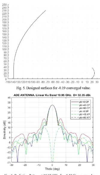
The best result of these first stage was found at -0.19 value, profiles of ADE antenna are shown in Fig.5, Fig.6 and Fig.7 shows that level of cross-polar component is around
43dB so the requirement is reached, the directivity for reception frequencies at Ku band are 32.35 dBi and 34.05 dBi Respectively to both lower frequencies. SLL are acceptable for 10.95 GHz and 12.7 GHz around -14 dB and -13 dB for each case.
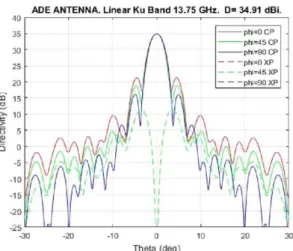
Results presented in Fig.8 and Fig 9 show that the reached level of the cross-polar component has a value around 40 dB. The directivity for reception frequencies at Ku band are 34.91 dBi and 35.44dBi Respectively, to both upper frequencies. SLL for 13.75GHz and 14.5GHz are -14 dB and -13.5 dB respectively.
Fig. 5. Designed surfaces for -0.19 converged value.
Fig. 6. Radiation Pattern at 10.95 GHz for -0.19 Converge value.
Thets (deg)
-10 o
Thela (deg)
Fig. 8. Radiation Pattern at 13.75 GHz for -0.19 Converged value.
Fig. 9. Radiation Pattern at 14.5 GHz for -0.19 Converged value.
Second Stage
• First Design
Results were obtained from the optimized program with different objective values. A parabolic reflector with elliptical rim (n=2 instead of n=1.95) with dimensions 458 mm x 440 mm. Table III presents a summary of the results obtained from optimization program: Directivity and Cross polar Component (XP) in -1dB main beam are presented:
• Subreflector diameter is 63.64 mm.
• Length from the reflector vertex to reflector edge at 229 mm is 64.92 mm.
• Length from the reflector vertex to reflector edge at 220 mm is 59.26 mm.
• Length from the reflector vertex to subreflector further point is 174.74 mm (without thickness).
T A B L E III. RESULTS OF THE FIRST DESIGN OF RADIATION PATTERN
LINK RX TX Frequency [GHz] 10.95 12.75 13.75 14.50 Parameters Directivity [dBi] 32.23 33.95 34.35 34.86 CP/XP at -1dB 47.79 41.50 43.79 46.32 First SLL [dB] -19.00 -18.19 -18.32 -18.02
Fig. 10. Designed surfaces of selected solution.
• Second Design
The geometry that is shown in this section is the one which has the best results tanks to low side lobe levels in high frequencies and the cross-polar component, these two facts are the most significant requirements when implementing an antenna in satellite communications. these results were obtained from the optimized program with different objective values, the main idea was design a parabolic reflector with elliptical rim (n=2 instead of n=1.95) with dimensions: 458 mm x 440 mm. Fig. 10 shows the geometry of the system and Table IV presents the summary of results from this optimization.
Fig.11. Radiation Pattern at 10.95 GHz of selected solution.
Subreflector diameter is 64.42 mm.
Length from the reflector vertex to reflector edge at 229 mm is 69.2 mm.
Length from the reflector vertex to reflector edge at 220 mm is 63.12 mm.
Length from the reflector vertex to subreflector further point is 162.67 mm (without thickness).
Fig.12. Radiation Pattern at 12.75 GHz of selected solution.
Fig.14. Radiation Pattern at 13.75GHz of selected solution.
Fig.13. Radiation Pattern at 14.5 GHz of selected solution. In Fig. 11 and Fig. 12 it can be seen that level of cross-polar component is reached, it has a value around 40 dB, looking at the Radiation Pattern. The directivity for reception frequencies at Ku band are 32.33 dBi and 33.22 dBi respectively. SLL for 13.75 GHz and 14.5 GHz are -17 dB and -20 dB for each case, which is an important limitation in this design.
The results shown in Fig. 13 and Fig. 14 stablish that the reached level of cross-polar component has a value around 40 dB, the directivity for transmission frequencies at Ku band are 34.10 dBi and 33.22 dBi for both frequencies. SLL for 13.75 GHz and 14.5 GHz are -18 dB and -17 dB.
T A B L E I V . RESULTS OF THE SECOND DESIGN OF RADIATION PATTERN LINK RX TX Parameters Frequency [GHz] 10.95 12.75 13.75 14.50 Directivity [dBi] 32.33 33.22 34.10 34.95 CP/XP at -1dB 39.90 41.86 46.58 45.66 First SLL [dB] -17.69 -20.43 -18.05 -17.19 V. CONCLUSIONS
A D E (Axially displaced Ellipse) configuration antenna offers compactness to meet lightweight requirements in satellite applications. In general terms the results from convergence value equal to -0.19, meets the design expectations for S A T C O M applications.
The industry is interested in meeting the requirements at the secondary lobes for high frequencies, from last design results of second stage, we conclude that the SLL are at -18 dB, despite of not meeting directivity at frequencies of
12.7GHz and 13.75 GHz. The SLL objectives at high frequencies were reached and the cross-polar component (XPD) goals defined in the specifications, in all cases were successfully fulfilled.
REFERENCES
[1] B. P. Kumar, C. Kumar, V. S. Kumar and V. V. Srinivasan, "Design of an axially displaced ellipsoid reflector antenna for a 4.6m diameter ship-borne transportable terminal at S-band," 2015 I E E E Applied Electromagnetics Conference (AEMC), Guwahati, 2015, pp. 1-2. [2] C . Granet, “Designing axially symmetric Cassegrain or Gregorian
dual-reflector antennas from combinations of prescribed geometric parameters,” I E E E Antennas and Propagation Magazine, pp. 82-89, April 1998.
[3] Telecomunications Centre National d'Etudes des Télécommunication, “Radiating Horns with low crosspolarisation over a Large Bandwith,” France, 1989.
[4] C. A. Balanis, “Antenna Theory : Analysis and Design,” John Wiley & Sons, 2016.
[5] C H A M P , from T I C R A , v. 1. [6] G R A S P , from T I C R A , v. 8.
[7] B . Galocha Iragüen, "Design report of a reflector for "Terminal S A T C O M Submarino P1"project at Ku band," Grupo de Radiacion: Departamento de Señales, Sistemas y Radiocomunicaicones. Universidad Politecnica de Madrid, M A D R I D , January 2017.