Performance Improvement of Ad Hoc Networks with ZRP using Route Maintenance
84
0
0
Texto completo
(2)
(3) c Alejandro Amı́n Lemus Amezcua, 2002 °.
(4)
(5) Instituto Tecnológico y de Estudios Superiores de Monterrey Campus Monterrey División de Electrónica, Computación, Información y Comunicaciones The members of the thesis committee recommended the acceptance of the thesis of Alejandro Amı́n Lemus Amezcua as a partial fulfillment of the requirements for the degree of Master of Science in. Electronic Engineering Major in Telecommunications Thesis Committee. César Vargas Rosales, Ph.D. Advisor. Daniel Sergio Martı́nez Ramı́rez, M.Sc.. José Ramón Rodrı́guez Cruz, Ph.D. Synodal. Synodal. Approved. David Garza Salazar Ph.D. Director de los programas de Posgrado en Electrónica, Computación, Información y Comunicaciones. December 2002.
(6)
(7) Acknowledgments To God To let to me arrive at this moment and for helping me to make specific this so important goal in my life. I want to thank to the Instituto Tecnológico y de Estudios Superiores de Monterrey for allowing me to study graduate studies. I am very grateful with my thesis advisor, Ph.D. César Vargas Rosales, for his teaching, suggestions, friendship and patient. I wish to thank to Ph.D. José Ramón Rodrı́guez Cruz and M.Sc. Daniel Sergio Martı́nez Ramı́rez, for their comments and suggestions to enhance my thesis. I also thank for all the professors who contributed in each stage of my formation, by to have shared their knowledge and experiences, by their patience, dedication, support and motivation to follow ahead, since without its important east contribution work had not been possible. To my girlfriend and friend Ing. Cecilia González Ortı́z by her love, understanding and support. To all my friends at the CET, specially to Dulce, Rafael, Paty, Araceli, LLuvia, Rodolfo, Abraham, Luis, Aldo, Edson and Rene without excluding any person..
(8)
(9) ♦ To my parents, for their effort, love, attentions, constant and disinterested support that always have offered to me and for having believed in me and to my dear sister Brenda Nely. ♦ Alejandro Amı́n Lemus Amezcua.
(10)
(11) Abstract. Zone Routing Protocol (ZRP) is a hybrid routing protocol for Ad-Hoc networks. This protocol divides the network into overlapping routing zones and runs independent protocols that study within and between these zones. Intra-zone protocol (IARP) operates within a zone and learns all possible routes. So, all nodes inside of a zone know about its zone topology very well. This protocol that will run in an intrazone is not defined, but can be any proactive protocol. Different zones may operate with different protocols. Interzone protocol (IERP) is a reactive protocol which consist of a source node by finding a destination node which is not located inside of the same zone by sending RREQ messages to all border nodes until the destination node is found. The routing zone diameter is variable and this should be chosen optimally for a scaled topology. ZRP is based on two procedures: Intrazone Routing Protocol (IARP) and Interzone Routing Protocol (IERP). Through the use of IARP, each node knows the distance which separates it from other node present in its routing zone. The true protocol IARP is not specified and can be implemented starting from various derivated protocols based on “Distance Vector Protocol” such as AODV, for example. In this research, we evaluate and measure using simulation the different maintenance strategies of a route in Ad-Hoc networks with ZRP by employing the Floyd-Warshall algorithm, with the objective of obtaining a better performance..
(12)
(13) Resumen. El Protocolo de Enrutamiento (ZRP por sus siglas en inglés) es un protocolo hibrido para redes Ad-Hoc. Este protocolo divide la red en zonas de enrutamiento sobrepuestas y corre protocolos independientes que estudia dentro y entre estas zonas. El protocolo Intrazona opera dentro de una zona y aprende todas las rutas posibles. Ası́ que, todos los nodos dentro de una zona conocen muy bien su topologı́a de zona. El protocolo, correrá en una intrazona no está definido, pero puede ser cualquier protocolo proactivo. Las diferentes zonas pueden operar con diferentes protocolos. El protocolo intrazona es un protocolo reactivo donde un nodo origen encuentra un nodo destino, el cual no está localizado dentro de la misma zona y mediante el envı́o de mensajes RREQ a todos los nodos de las fronteras. Esto continúa hasta que el nodo estino es encontrado. El diámetro de la zona de ruta es variable y puede ser escogido optimamente mediante una topologı́a escalada. El ZRP está basado en dos procedimientos: Protocolo de enrutamiento de Intrazona (IARP, por sus siglas en inglés) y Protocolo de enrutamiento de Interzona (IERP, por sus siglas en inglés). A través del uso de IARP, cada nodo conoce la distancia que lo separa de cada uno de los nodos presentes en su zona de enrutamiento. IARP, no está especificado y puede ser implementado comenzando a partir de varios protocolos derivados de los “protocolos de vector de distancia” tales como el AODV, por ejemplo. En esta nvestigación, evaluamos y medimos mediante simulación las diversas estrategias de mantenimiento de una ruta en una red Ad-Hoc, empleando para ello el algoritmo de Floyd-Warshall, con el objetivo de obtener un mejor desempeño..
(14)
(15) Contents. List of Figures. v. List of Tables Chapter 1 Introduction 1.1 Definition of the problem 1.2 Objective . . . . . . . . 1.3 Justification . . . . . . . 1.4 Thesis Organization . . .. vii. . . . .. . . . .. . . . .. . . . .. . . . .. . . . .. . . . .. . . . .. . . . .. . . . .. . . . .. . . . .. . . . .. . . . .. . . . .. . . . .. . . . .. . . . .. . . . .. Chapter 2 Routing and Ad-Hoc Networks 2.1 Routing . . . . . . . . . . . . . . . . . . . . . . . . . . . . 2.1.1 Circuit Switching and Packet Switching . . . . . . . 2.1.2 Route Discovery . . . . . . . . . . . . . . . . . . . . 2.1.3 Route Maintenance . . . . . . . . . . . . . . . . . . 2.2 Ad-Hoc Routing Protocols . . . . . . . . . . . . . . . . . . 2.2.1 Reactive Routing Protocol . . . . . . . . . . . . . . 2.2.2 Proactive protocols . . . . . . . . . . . . . . . . . . 2.2.3 Reactive protocols . . . . . . . . . . . . . . . . . . 2.2.4 Hybrid protocols . . . . . . . . . . . . . . . . . . . 2.2.5 Optimized Link State Routing (OLSR) . . . . . . . 2.2.6 Temporally-Ordered Routing Algorithm (TORA) . 2.2.7 The Ad Hoc On Demand Distance Vector (AODV) 2.3 Zone Routing Protocol (ZRP) . . . . . . . . . . . . . . . . 2.3.1 Protocol of Interzone Routing (IERP) . . . . . . . . 2.3.2 The Intrazone Routing Protocol (IARP) . . . . . . 2.3.3 Routing Zones and Intrazone Routing . . . . . . . . 2.3.4 The Bordercast Resolution Protocol (BRP) . . . . . 2.3.5 Routing Zone Based Querying . . . . . . . . . . . . i. . . . .. . . . . . . . . . . . . . . . . . .. . . . .. . . . . . . . . . . . . . . . . . .. . . . .. . . . . . . . . . . . . . . . . . .. . . . .. . . . . . . . . . . . . . . . . . .. . . . .. . . . . . . . . . . . . . . . . . .. . . . .. . . . . . . . . . . . . . . . . . .. . . . .. . . . . . . . . . . . . . . . . . .. . . . .. . . . . . . . . . . . . . . . . . .. . . . .. 1 1 1 2 2. . . . . . . . . . . . . . . . . . .. 3 3 4 5 5 6 6 6 6 7 7 8 9 9 10 12 12 13 14.
(16) ii. CONTENTS. Chapter 3 Survivable Networks 3.1 Overview . . . . . . . . . . . . . . . . . . . 3.2 Definition of Survivability . . . . . . . . . 3.3 Characteristics of Survivable Systems . . . 3.4 Network Management Basics . . . . . . . . 3.4.1 Network Management Architecture 3.4.2 Performance Management . . . . . 3.4.3 Accounting Management . . . . . . 3.4.4 Fault Management . . . . . . . . . 3.4.5 Security Management . . . . . . . .. . . . . . . . . .. . . . . . . . . .. . . . . . . . . .. . . . . . . . . .. . . . . . . . . .. . . . . . . . . .. Chapter 4 Simulation of ZRP 4.1 Evaluation of ZRP . . . . . . . . . . . . . . . . . . . 4.1.1 Explanations Of The “Zone Routing Protocol” 4.2 Route Maintenance . . . . . . . . . . . . . . . . . . . 4.3 Constructing the Bordercast Tree . . . . . . . . . . . 4.4 Routing Zone Based Route Maintenance . . . . . . . 4.4.1 IERP Implementation . . . . . . . . . . . . . 4.4.2 State Machine IERP . . . . . . . . . . . . . . 4.4.3 IARP Implementation . . . . . . . . . . . . . 4.4.4 State Machine IARP . . . . . . . . . . . . . . 4.4.5 BRP Implementation . . . . . . . . . . . . . . 4.4.6 State Machine BRP . . . . . . . . . . . . . . . 4.5 Performance Measures . . . . . . . . . . . . . . . . . Chapter 5 Numerical Results 5.1 Evaluated Scenarios . . . . 5.2 Scenario One Results . . . 5.3 Scenario Two Results . . . 5.4 Scenario Three Results . . 5.5 Scenario Four Results . . . 5.6 Comparison . . . . . . . .. . . . . . .. . . . . . .. . . . . . .. . . . . . .. . . . . . .. . . . . . .. . . . . . .. . . . . . .. . . . . . .. . . . . . .. . . . . . .. . . . . . .. . . . . . .. . . . . . .. . . . . . .. . . . . . . . . .. . . . . . . . . .. . . . . . . . . .. . . . . . . . . .. . . . . (ZRP) . . . . . . . . . . . . . . . . . . . . . . . . . . . . . . . . . . . . . . . .. . . . . . .. . . . . . .. . . . . . .. . . . . . .. . . . . . . . . .. . . . . . . . . . . . .. . . . . . .. . . . . . . . . .. . . . . . . . . . . . .. . . . . . .. . . . . . . . . .. . . . . . . . . . . . .. . . . . . .. . . . . . . . . .. . . . . . . . . . . . .. . . . . . .. . . . . . . . . .. . . . . . . . . . . . .. . . . . . .. . . . . . . . . .. . . . . . . . . . . . .. . . . . . .. . . . . . . . . .. . . . . . . . . . . . .. . . . . . .. . . . . . . . . .. 17 17 18 19 20 20 21 21 22 22. . . . . . . . . . . . .. 23 23 23 24 25 25 26 28 30 31 32 35 38. . . . . . .. 41 41 42 45 49 53 56. Chapter 6 Conclusions. 59. Appendix A Network Algorithms A.1 Shortest Path Algorithm . . . . . . . . . . . . . . . . . . . . . . . . . . . . A.1.1 The Floyd-Warshall Algorithm . . . . . . . . . . . . . . . . . . . .. 61 61 61.
(17) CONTENTS. iii. Bibliography. 63. Vita. 65.
(18) iv. CONTENTS.
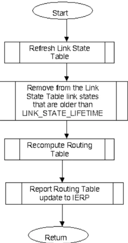
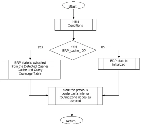
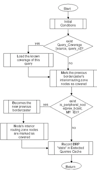
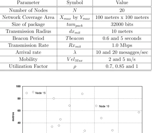
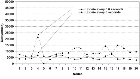
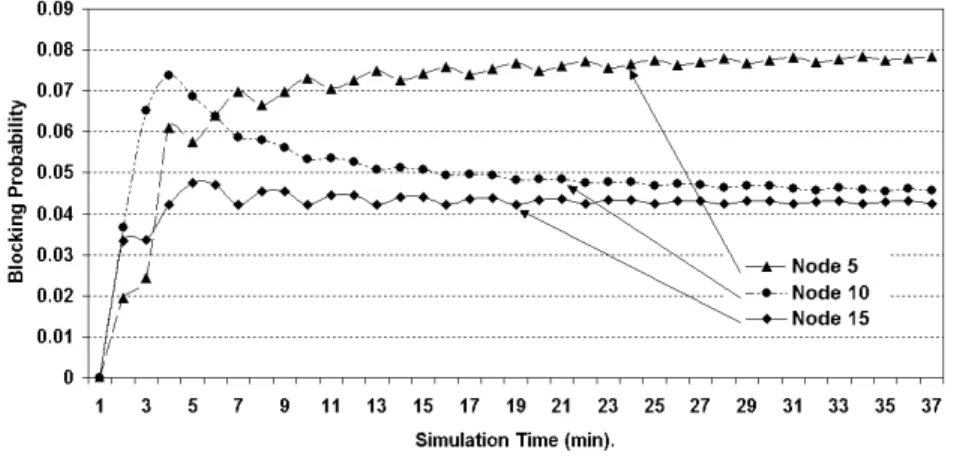
(19) List of Figures. 2.1 2.2 2.3 2.4 2.5. Previous Routing Tendencies. . . . . . . . New ZRP Architecture. . . . . . . . . . . . An example of IERP operation. . . . . . . Routing Zone of node A (radius = 2 hops). Route zone based querying. . . . . . . . .. . . . . .. . . . . .. . . . . .. . . . . .. . . . . .. . . . . .. . . . . .. . . . . .. . . . . .. . . . . .. . . . . .. . . . . .. . . . . .. . . . . .. . . . . .. . . . . .. 7 10 12 13 14. 4.1 4.2 4.3 4.4 4.5 4.6 4.7 4.8 4.9 4.10 4.11 4.12 4.13. Root Directed Bordercast (RDB) . . . . . . . . Packet Format IERP . . . . . . . . . . . . . . . Flow chart for the Route Request . . . . . . . . Flow chart for the Route Reply . . . . . . . . . Packet Format IARP . . . . . . . . . . . . . . . Flow chart for the IARP updated . . . . . . . . Flow chart for the Deliver . . . . . . . . . . . . Flow chart for the Refresh Link State Table . . Packet Format BRP . . . . . . . . . . . . . . . Send BRP . . . . . . . . . . . . . . . . . . . . . Deliver BRP . . . . . . . . . . . . . . . . . . . . Network . . . . . . . . . . . . . . . . . . . . . . Route from node source 1 to node destination 6. . . . . . . . . . . . . .. . . . . . . . . . . . . .. . . . . . . . . . . . . .. . . . . . . . . . . . . .. . . . . . . . . . . . . .. . . . . . . . . . . . . .. . . . . . . . . . . . . .. . . . . . . . . . . . . .. . . . . . . . . . . . . .. . . . . . . . . . . . . .. . . . . . . . . . . . . .. . . . . . . . . . . . . .. . . . . . . . . . . . . .. . . . . . . . . . . . . .. . . . . . . . . . . . . .. 25 27 29 29 30 32 33 34 34 36 37 40 40. 5.1 5.2 5.3 5.4 5.5 5.6. Generation of the scenario of 20 Nodes in the network. . . . . . . . . . . . Average delay for the 20 Nodes in the network. . . . . . . . . . . . . . . . Comparative of average delay for 20 Nodes in the network, ρ = 0.85. . . . . Blocking Probability update every 0.6 seconds, ρ = 0.85. . . . . . . . . . . Blocking Probability update every 5 seconds, ρ = 0.85. . . . . . . . . . . . Generation of average delay of the 20 Nodes with Maintenance in the network, update every 0.6 seconds. . . . . . . . . . . . . . . . . . . . . . . . . Comparative of average delay with Maintenance in the network, update every 0.6 seconds. . . . . . . . . . . . . . . . . . . . . . . . . . . . . . . . . . . . Average delay with Maintenance and ρ = 0.85. . . . . . . . . . . . . . . . .. 42 43 43 44 44. 5.7 5.8. v. . . . . .. . . . . .. 45 46 46.
(20) vi. LIST OF FIGURES 5.9 5.10 5.11 5.12 5.13 5.14 5.15 5.16 5.17 5.18 5.19 5.20 5.21 5.22 5.23 5.24 5.25. Blocking Probability with Maintenance, ρ = 0.85, update every 0.6 seconds. Average delay with Maintenance, update every 5 seconds. . . . . . . . . . . Blocking Probability with Maintenance, update every 5 seconds, ρ = 0.85. . Comparative of average delay with double λ and Maintenance, update every 0.6 seconds. . . . . . . . . . . . . . . . . . . . . . . . . . . . . . . . . . . . Comparative of average delay with double λ and Maintenance, update every 0.6 seconds. . . . . . . . . . . . . . . . . . . . . . . . . . . . . . . . . . . . Simulation Time of Blocking Probability with double λ and Maintenance, update every 0.6 seconds. . . . . . . . . . . . . . . . . . . . . . . . . . . . . Generation of Delay with double λ and Maintenance, update every 5 seconds. Simulation Time of Delay with double λ and Maintenance, update every 5 seconds. . . . . . . . . . . . . . . . . . . . . . . . . . . . . . . . . . . . . . Simulation Time of Blocking Probability with double λ and Maintenance, update every 5 seconds, ρ = 0.85. . . . . . . . . . . . . . . . . . . . . . . . Comparative of Delay for 20 Nodes with velocity at 5 m/s and Maintenance, update every 0.6 seconds. . . . . . . . . . . . . . . . . . . . . . . . . . . . . Comparative of average delay with velocity at 5 m/s and Maintenance, ρ = 0.85, update every 0.6 seconds. . . . . . . . . . . . . . . . . . . . . . . . . Simulation Time of Delay with velocity at 5 m/s and Maintenance, update every 0.6 seconds. . . . . . . . . . . . . . . . . . . . . . . . . . . . . . . . . Simulation Time of Blocking Probability with velocity at 5 m/s and Maintenance, update every 0.6 seconds. . . . . . . . . . . . . . . . . . . . . . . Comparative of Blocking Probability for 20 Nodes in the Network. . . . . . Comparative of Blocking Probability with Maintenance in the network. . . Comparative of Blocking Probability with double λ. . . . . . . . . . . . . . Comparative of Blocking Probability with velocity at 5 m/s. . . . . . . . .. A.1 Flow Chart of Maintenance Process . . . . . . . . . . . . . . . . . . . . . .. 47 47 48 49 50 51 51 52 52 53 54 54 55 56 56 57 57 62.
(21) List of Tables. 4.1 4.2 4.3 4.4 4.5. Structures Neighbor Table. Data Structure IERP. . . . Link State IARP. . . . . . Detected Query Cache. . . Query Coverage. . . . . .. . . . . .. . . . . .. . . . . .. . . . . .. . . . . .. . . . . .. . . . . .. 24 28 31 35 35. 5.1. Fixed Simulation Parameters for scenarios. . . . . . . . . . . . . . . . . . .. 42. vii. . . . . .. . . . . .. . . . . .. . . . . .. . . . . .. . . . . .. . . . . .. . . . . .. . . . . .. . . . . .. . . . . .. . . . . .. . . . . .. . . . . .. . . . . .. . . . . .. . . . . .. . . . . .. . . . . .. . . . . ..
(22) viii. LIST OF TABLES.
(23) Chapter 1 Introduction. An important element in network management is routing, which consists of a set of decision rules used to establish the connection from origin to a destination in the network. Routing is the selection of a trajectory with the purpose of making a connection of origin and destination nodes by means of a of links concatenation. The Zone Routing Protocol (ZRP) takes a first yet time-tested approach for protocol improvement by constructing a way to hybridize table-driven and on-demand protocols. ZRP uses zones that are similar like clusters, but instead of hierarchical routing between clusters still being used, the special border nodes are dynamically selected that connect adjacent zones. A zone radius parameter dynamically adjusts the size of the zone, in terms of the number of hops like the network topology changes. A different routing protocol can be used between zones as compared to the one used within a zone. A proactive scheme is used inside the zone, and outside the path zones are discovered only reactively. This approach is almost guaranteed to find a happy medium between the two extremes that exhibit improved properties, [21].. 1.1. Definition of the problem. The problem consists on evaluation and determining a more efficient network management which employs routing maintenance by means of a routing protocol and as consequence a better information maintenance, which is carried on the network.. 1.2. Objective. To evaluate and to measure the different maintenance strategies of a route in an Ad-Hoc network when the routes are interrupted by fault, interference, or mobility of a node. 1.
(24) 2. 1.3. CHAPTER 1. INTRODUCTION. Justification. Because the maintenance of a route in an Ad-Hoc network is very important for the information security which travels through it, we will focus to study some important problems for the improvement of these. For example, when a node moves or the route breaks due to a fault, or there is high interference between transmitter and the receiver.. 1.4. Thesis Organization. This research is organized as follows. In Chapter 2, the fundamental concepts about Ad-Hoc networks are presented. Next, in Chapter 3, some definitions about survivable networks and their characteristics will be presented. In Chapter 4 the implementation of ZRP is described by simulations just as the performance parameters: blocking and network probability, average and network delays and route maintenance will be explained. In addition, in Chapter 5, the numerical results and their discussions are shown. Finally, in Chapter 6, the conclusions are presented..
(25) Chapter 2 Routing and Ad-Hoc Networks In this chapter, some concepts for Routing and basic descriptions about Circuit Switching, Packet Switching, Route Discovery and Route Maintenance will be explained. Finally, some Ad-Hoc protocols are also discussed.. 2.1. Routing. Routing is the main process used by Internet hosts to deliver packets. Internet uses a hop-by-hop routing model, which means that each host or router that handles a packet examines the Destination Address in the IP header, computes the next hop that will bring the packet one step closer to its destination, and delivers the packet to the next hop, while the process is repeated. To make this work, two things are needed. First, routing tables match destination addresses with next hops. Second, routing protocols determine the contents of these tables, [15]. Routing is the act of moving information across an internetwork from a source to a destination. Along the way, at least one intermediate node typically is encountered. Routing is often contrasted with bridging, which might seem to accomplish precisely the same thing to the casual observer. The primary difference between both is the following: bridging occurs at Layer 2 (the link layer) of the OSI reference model. Whereas routing occurs at Layer 3 (the network layer). This distinction provides routing and bridging with different information to use in the process of moving information from source to destination, so both functions accomplish their task in different ways. The topic of routing has been covered in computer science literature for more than two decades, but routing achieved commercial popularity as late as the mid-1980s. The primary reason for this time lag is that networks in the 1970s were simple, homogeneous environments. Only relatively recently has large-scale internetworking become popular. Routing involves two basic activities: determining optimal routing paths and transporting information groups (typically called packets) through an internetwork. In the 3.
(26) 4. CHAPTER 2. ROUTING AND AD-HOC NETWORKS. context of routing process, the latter of these is referred to as packet switching. Although packet switching is relatively straightforward, the path determination can be very complex. Routing protocols use metrics to evaluate which path will be the best for a packet to travel. A metric is a measurement standard, such as path bandwidth, that is used by routing algorithms to determine the optimal path to a destination. To aid the process of path determination, routing algorithms initialize and maintain routing tables, which contain the route information. The route information varies depending of the routing algorithm used. Routing algorithms fill routing tables with a variety of information. Destination/next hop associations tell a router that a particular destination can be reached optimally by sending the packet to a particular router representing the “next hop” on the way to the final destination. When a router receives an incoming packet, it checks the destination address and attempts to associate this address with a next hop. It can be differentiated based on several key characteristics. First, the algorithm designer particular goals affect the operation of the resulting routing protocol. Second, various types of routing algorithms exist, and each algorithm has a different impact on network and router resources. Finally, routing algorithms use a variety of metrics that affect calculation of optimal routes. The following sections analyze these routing algorithm attributes.. 2.1.1. Circuit Switching and Packet Switching. Circuit Switching is a type of communications in which a dedicated channel (or circuit) is established for the duration of a transmission. The most ubiquitous circuit-switching network is the telephone system, which links together wire segments to create a single unbroken line for each telephone call. Circuit-switching systems are ideal for communications that require data to be transmitted in real-time. Packet-switching networks are more efficient if some amount of delay is acceptable. Circuit-switching networks are sometimes called connection-oriented networks. Note, however, that although packet switching is essentially connectionless, a packet switching network can be made connection-oriented by using a higher-level protocol. TCP, for example, makes IP networks connection-oriented. Refers to protocols in which messages are divided into packets before they are sent. Each packet is then transmitted individually and can even follow different routes to its destination. Once all the packets forming a message arrive at the destination, they are recompiled into the original message..
(27) 2.1. ROUTING. 2.1.2. 5. Route Discovery. Any routing protocol depends on connectivity information. The active discovery packets collect this information and store it on neighbor nodes. In fact, the neighbor discovery packets are more complex, since they also announce interface names and link status information. Each node in the ad hoc network periodically broadcasts an active beacon packet whose task is to announce the node’s presence. This is done by putting information in the persistent data storage area of all neighbor nodes. The most important information is the sending node’s and outgoing interface’s names, [4]. When an incoming call arrives at node i toward a destination node j and there is no route available to route the packet to j, i initiates a route discovery phase. Here, i has two options; either to flood the network with a route query in whose case the route query packets are broadcasted into the whole network, or instead, to limit the discovery in a smaller region of the network, if some kind of location prediction model for j can be established.. 2.1.3. Route Maintenance. An intermediate node i, upon reception of a data packet, first processes the routing header and then forwards the packet to the next hop. In addition of this, node i sends an explicit message to the previous node on an attempt to examine whether bi-directional link can be established with the node where the packet is received from it. The protocol, therefore, does not assume bidirectional links but in contrast,the nodes exercise the possibility of having bidirectional links. In this way, nodes that forward a data packet will always have routing information to send the future acknowledgement back to the source. After a route is acquired, knowledge of the local topology can be used to bypass link failures and sub-optimal route segments. The resulting increase in route lifetime and reduction in route length translates in to a more stable, lower latency, higher throughput network application, [1]. When neighboring nodes in a route move out of direct radio contact, the resulting link failure interrupts data flow across the route. For a purely reactive routing protocol, any route that includes the broken link immediately fails. To maintain end-to-end connectivity, a new route discovery / repair would have to be initiated. Until a replacement route or route segment is discovered, incoming data packets are either delayed or dropped, degrading application performance. Because the routing zone provides a node with a view beyond its own neighborhood, many link failures can be instantly bypassed. As long as the former neighbor remains within the routing zone, incoming data packets can be redirected around a broken link, through an active multi-hop path to the former neighbor..
(28) 6. CHAPTER 2. ROUTING AND AD-HOC NETWORKS. 2.2 2.2.1. Ad-Hoc Routing Protocols Reactive Routing Protocol. Reactive Routing Protocol is a bandwidth efficient on-demand routing protocol for Mobile Ad-Hoc Networks. The protocol comprises of two main functions of Route Discovery and Route Maintenance. Route Discovery function is responsible for the discovery of new route, when one is needed and Route Maintenance function is responsible for the detection of broken links and repair an existing route, [1]. The protocol achieves its bandwidth efficiency by using Incremental Search Method for Route Discovery and Surroundings Repair Method for Route Maintenance. Incremental Search Method limits the number of routing messages such that the number of links traversed during Route Discovery are minimized and hence bandwidth is efficiently utilized. And by using Surroundings Repair Method a node attempts to repair its surroundings in the event of a link failure, in order to find an alternate route skipping this broken link and thus it attempts to minimize the routing overhead. Simulation results an illustrative way to show the performance and an efficient utilization of bandwidth by Reactive Routing Protocol. The Ad-Hoc routing protocols and their key characteristics are the following.. 2.2.2. Proactive protocols. 1. Adaptive system of routing based on the exchange of control packets. 2. Continuously update the information reachability in the routing tables of the nodes. 3. Route is immediately available when is requested. 4. Substantial bandwidth is used for large traffic control, which may never be used.. 2.2.3. Reactive protocols. 1. Do not take initiative by finding a route. 2. Attempt to discover a route only “on demand” by flooding its Query. 3. Bandwidth is not consumed for sending information which is not required. 4. Once a route is known, bandwidth is consumed for data transmission. 5. Enormous bandwidth is consumed for the global search (flooding). 6. Large delays in sending data packets..
(29) 2.2. AD-HOC ROUTING PROTOCOLS. 2.2.4. 7. Hybrid protocols. 1. A mixture of proactive and reactive schemes or a derivative of any both schemes. 2. Optimization of either of two routing techniques. 3. Difficulty to specify its application domain, so an optimization is arbitrarily dispersed.. Figure 2.1: Previous Routing Tendencies.. 2.2.5. Optimized Link State Routing (OLSR). OLSR is a proactive routing protocol for mobile ad- hoc networks. The protocol inherits the stability of a link state algorithm and has the advantage of having routes immediately available when needed due to its proactive nature. OLSR is an optimization over the pure link state protocol, tailored for mobile ad hoc networks, [25]. The Optimized Link State Routing Protocol (OLSR) is developed for mobile ad hoc networks. It operates like a table driven and proactive protocol thus exchanges topology information with other nodes in the network regularly. The nodes which are selected as a multipoint relay (MPR) by some neighbor nodes that announce this information periodically in their control messages. Thereby, a node announces to the network, that it has reachability to the nodes, which have selected it as MPR. In route calculation, the MPRs are used to form the route from a given node to any destination in the network. The protocol uses the MPRs to facilitate efficient flooding of control messages in the network, [25]..
(30) 8. CHAPTER 2. ROUTING AND AD-HOC NETWORKS. 2.2.6. Temporally-Ordered Routing Algorithm (TORA). TORA is a network routing protocol which has been designed for use in Mobile Wireless Networks. Such, a network can be envisioned as a collection of routers (equipped with wireless receiver/transmitters) which are free to move arbitrarily. The status of the communication links between the routers, at any given time, is a function of their positions, transmission power levels, antenna patterns, cochannel interference levels, etc. The mobility of the routers and variability of other connectivity factors result in a network with a potentially rapid and unpredictably changing topology. Congested links are also an expected characteristic of such a network as wireless links inherently have significantly a lower capacity than hardwired links and are therefore more prone to congestion. TORA is designed to minimize reaction to topological changes. A key concept in its design is that it decouples the generation of potentially far-reaching control message propagation from the rate of topological changes. Such messaging is typically localized in a very small set of nodes near the change without having to resort to a dynamic, hierarchical routing solution with its attendant complexity, [20]. TORA has the following desirable properties, which make it well suited for use in the mobile wireless-networking environment: 1. Executes distributedly. 2. Provides loop-free routes. 3. Provides multiple routes (to alleviate congestion). 4. Establishes routes quickly (so they may be used before the topology changes). 5. Minimize algorithmic reactions/communication overhead (to conserve available bandwidth and increase adaptability). The basic concepts used to minimize communication overhead and maximize routing efficiency are as follows: 1. Routes established only when are necessary by constructing a directed acyclic graph rooted at the destination using a “query/reply” process. 2. Reaction to link failure only when is necessary (i.e., when a node loses its last downstream link). 3. Scope of failure reactions minimized (i.e., the number of nodes that must participate). 4. No reaction to link activation..
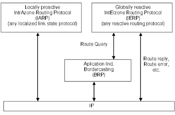
(31) 2.3. ZONE ROUTING PROTOCOL (ZRP). 2.2.7. 9. The Ad Hoc On Demand Distance Vector (AODV). The Ad hoc On Demand Distance Vector (AODV) routing algorithm is a routing protocol designed for ad hoc mobile networks. AODV is capable of both unicast and multicast routing. It is an on demand algorithm, meaning that it builds routes between nodes only as desired by source nodes. It maintains these routes as long as they are needed by the sources. Additionally, AODV forms trees which connect multicast group members. The trees are composed of group members and the nodes needed to connect these members. AODV uses sequence numbers to ensure the freshness of routes. It is loop-free, self-starting, and scales to large numbers of mobile nodes. AODV builds routes using a route request / route reply query cycle. When a source node desires a route to a destination for which it does not already have a route, it broadcasts a route request (RREQ) packet across the network. Nodes receiving this packet and update their information from the source node and set up backwards pointers to the source node in the route tables. In addition to the source node’s IP address, current sequence number, and broadcast ID, the RREQ also contains the most recent sequence number for the destination of which the source node is aware. A node receiving the RREQ may send a route reply (RREP) if it is either the destination or if it has a route to the destination with corresponding sequence number greater than or equal to that contained in the RREQ. If this in case, it unicasts a RREP back to the source. Otherwise, it rebroadcasts the RREQ. Nodes keep track of the RREQ’s source IP address and broadcast ID. If they receive a RREQ packet which they have already processed, they discard the RREQ and do not forward it. [23].. 2.3. Zone Routing Protocol (ZRP). ZRP is a hybrid model between a proactive protocol and a reactive protocol, (see Figure 2.1). The principal problem in the development of a routing protocol for Ad Hoc networks lies on the fact that to determine the course of a package of data, the source node must at least know information making it possible to reach its close relations. On the other side, the network topology frequently changes. Moreover, as the number of nodes can be large, the number of potential destinations can also be, which requires significant data exchanges in frequent form. Thus the quantity of data update of the traffic can be consequent. That is in contradiction with the fact that all the updates in an inter-connected Ad-Hoc network circulate in the air and thus are expensive in resources, [11]. Protocol ZRP limits the proactive procedure only those close nodes and researching them through the network, although naturally it, is carried out through an efficient selection in the network, instead through researching all the network..
(32) 10. CHAPTER 2. ROUTING AND AD-HOC NETWORKS. Although a routing protocol is effective, the changes of network topologies must have only a local impact. In other words, the creation of a new bond for an end of network is a significant local event but not to reflect with the other end of the network. The proactive protocols tend to extend such topological changes on all the network, including broad costs. ZRP limits the propagation of such information in the vicinity only the zone where the modification of network topology took place, which limits the updates. In Figure 2.2 we can see the new architecture of ZRP, which is divided in three modules IARP, IERP, and BRP; the last two items are in narrow communication by means of route query in addition of which the three maintain communication with IP.. Figure 2.2: New ZRP Architecture.. 2.3.1. Protocol of Interzone Routing (IERP). The design of routing protocols in Ad-Hoc networks is influenced by link instability (due to node mobility) and limitations in available bandwidth just as transmission power. Traditional wired networks use proactive routing protocols, like OSPF [16] and RIP [9] to maintain up-to-date routes to all network nodes. More efficient proactive routing protocols have been developed for ad hoc networks, [6], [12], [17], [18], [24]. However, if we change frequently the topology in a practical ad hoc network can still produce an overwhelming amount of control traffic. Even worse, most of the acquired route information expires before it is ever used, making the proactive control traffic a poor investment of bandwidth. In contrast, reactive routing protocols, [13], [19], [21] only initiate a global, query-based, route discovery as routes are needed. While some delay is incurred in route acquisition, the amount of overhead traffic is generally much less than proactive routing protocols, because routing information is not wasted. For this reason, reactive protocols are generally viewed as being more suitable than proactive routing protocols for the power/ bandwidth limited mobile ad hoc network..
(33) 2.3. ZONE ROUTING PROTOCOL (ZRP). 11. Whereas IARP makes it possible to find paths inside a zone, IERP by itself is responsible to establish links between nodes whose distance, which separates them, is higher than the ray of zone. IERP support the techniques of bordercasting. This procedure is possible if each node knows the distance which separates it from all the nodes of its zone like their identity by the intermediary of protocol IARP. IERP operates as follows: the node source checks initially that the recipient is on its zone (once again, that is not possible if each node knows the contents of its zone). The Interzone Routing Protocol (IERP) is the global reactive routing component of Zone Routing Protocol (ZRP). IERP adapts existing reactive routing protocol implementations to take advantage of the known topology of each node’s surrounding r-hop neighborhood (routing zone), provided by the Intrazone Routing Protocol (IARP). The availability of routing zone routes allows IERP to suppress route queries for local destinations. When a global route discovery is required, the routing zone based bordercast service, [8] can be used to efficiently guide route queries outward, rather than blindly relaying queries from neighbor to neighbor. Once a route has been discovered, IERP can use routing zones to automatically redirect data around broken links. Similarly, suboptimal route segments can be identified and traffic re-routed along shorter paths. The effectiveness of bordercasting and zone based route maintenance improves with a increased routing zone radius. However, an increased routing radius requires additional proactive traffic to maintain a current view of a larger routing zone. Based on this tradeoff, it follows that networks characterized by a highly dynamic topology and/or low route demand favor smaller routing zones. In extreme cases, the routing zone reduces to zero hops (or one hop, for multiple channel networks) and route discovery degenerates into traditional flood searching. As the demand for new routes increases and/or the network topology stabilizes, larger routing zones become more appropriate. An example of this Route Discovery procedure is demonstrated in Figure 2.3. The source node S prepares to send data to the destination node D. The node S first checks if D is within its routing zone. If so, S already knows the route to node D. Otherwise, S sends a query to all its peripheral nodes (C, G, and H). Now, in turn, each one of these nodes, after verifying that D is not in its routing zone, forward the query to its peripheral nodes. In particular, the node H sends the query to node B, which recognizes D as being in its routing zone and responds to the query, indicating the forwarding path: S − H − B − D. A nice feature of this route discovery process is that a single route query can return multiple route replies. The quality of these returned routes can be determined based on hop count (or any other path metric) accumulated during the propagation of the query). The best route can be selected based on the relative quality of the route (i.e., choose the with the smallest hop count, or shortest accumulated delay), [7]..
(34) 12. CHAPTER 2. ROUTING AND AD-HOC NETWORKS. Figure 2.3: An example of IERP operation.. 2.3.2. The Intrazone Routing Protocol (IARP). Within the context of ZRP, we refer to the local proactive routing component as the IARP. IARP is not a specific routing protocol. In addition, it is a member of the limited-depth protocol family, it is to say, it belongs to proactive or link state routing protocols. In this document, we provide an implementation of a simple timer-based IARP. In addition, we provide a set of basic guidelines which can be used to convert an existing proactive routing protocol to an IARP. The IARP is a limited scope proactive routing protocol, which is used to support a primary global routing protocol. The scope of IARP is defined by the routing zone radius: the distance in hops which IARP route updates are relayed. IARP proactive tracking of local network connectivity provides support for route acquisition and route maintenance. First, routes to local destinations are immediately available, avoiding the traffic overhead and latency of a route discovery. When a global route discovery is required for more distant destinations, inefficient query broadcasting can be replaced by a more bandwidth efficient query bordercasting, [8], which directs queries to the periphery of the routing zone. Once routes have been discovered, IARP routing zone offers enhanced, real-time, route maintenance. Link failures can be bypassed by multiple hop paths within the routing zone. Similarly, suboptimal route segments can be identified, enabling traffic to be re-routed along shorter paths.. 2.3.3. Routing Zones and Intrazone Routing. A routing zone for a node X is defined as the set of nodes whose minimum distance in ”hops” from X is no greater than some parameter referred to as the zone radius. An.
(35) 2.3. ZONE ROUTING PROTOCOL (ZRP). 13. example of a radius R = 2 hop routing zone (for node A) is shown in Figure 2.4. Note that in this example nodes B through E are within the routing zone of A. Node G is outside A’s routing zone. Also note that E can be reached by a two link path from A, one with length 2 hops. Since the minimum is less than or equal than 2, E is within A’s routing zone. Peripheral nodes are nodes whose minimum distance to the node in question is equal exactly to the zone radius.. Figure 2.4: Routing Zone of node A (radius = 2 hops).. 2.3.4. The Bordercast Resolution Protocol (BRP). The bordercasting packet delivery service is provided by the Bordercast Resolution Protocol (BRP). BRP uses a map of an extended routing zone, provided by the local proactive Intrazone Routing Protocol (IARP), [8], to construct bordercast (multicast) trees along which query packets are directed. (Within the context of the hybrid ZRP, BRP is used to guide the route requests of the global reactive Interzone Routing Protocol (IERP), [9]). BRP employs special query control mechanisms to steer route requests away from areas of the network that have already been covered by the query. The combination of multicasting and zone based query control makes bordercasting an efficient and tunable service that is more suitable than flood searching for network probing applications like route discovery. Bordercasting is an efficient multicast packet delivery service used for guiding queries through the network. When each node proactively tracks the topology of its surrounding extended routing zone, the queries can be directed to the edge of the node’s routing zone rather than blindly being relayed to all neighbors. Special routing zone based query control mechanisms steer query packets away from regions of the network that have already been covered by the query..
(36) 14. CHAPTER 2. ROUTING AND AD-HOC NETWORKS. Within the context of ad hoc network routing, bordercasting is proposed as a more efficient and tunable alternative to broadcasting of route request messages for reactive (ondemand) routing protocols. We refer to any reactive routing protocol that bordercast route requests as an Interzone Routing Protocol (IERP). The link state information needed to support bordercasting is provided by a local proactive Intrazone Routing Protocol (IARP). Thus, a routing protocol based on bordercasting is actually hybrid reactive/proactive. For a properly chosen routing zone radius, IARP’s cost of tracking routing zone topology is larger than justified by the resulting savings in route discovery overhead through bordercasting.. 2.3.5. Routing Zone Based Querying. We illustrate the basic operation of routing zone based in route discovery through a simple (but as we will see, inefficient) IERP implementation. The source node, in need of a route to a destination node, first checks whether the destination lies within its routing zone. (This is possible since every node knows the content of its routing zone). If a path to the destination is known, no further route discovery processing is required. On the other hand, if the destination is not within the source’s routing zone, the source bordercasts a route query to all of its peripheral nodes. Upon receipt of the route query, each peripheral nodes executes the same algorithm. If the destination lies within its routing zone, a route reply is sent back to the source, indicating the route to the destination. Else where, this node forwards the query to its peripheral nodes. This process continues until the query has spread throughout the network, [8].. Figure 2.5: Route zone based querying. In Figure 2.5, node A has data to send to node L. Assuming each node’s zone radius is 2 hops, node L does not lie within A’s routing zone (which does include B, C, D, E, F , G). Therefore, A bordercasts a routing query to its peripheral nodes: D, F, E and G. Each one of these peripheral nodes checks whether L exists in its routing zone. Since L is not found in any of these nodes routing zones, the nodes bordercast the request to their peripheral.
(37) 2.3. ZONE ROUTING PROTOCOL (ZRP). 15. nodes. In particular, G bordercasts to K, which recognizes that L is in its routing zone and returns the requested route (L − K − G − A) to the query source A. The one-to-many nature of bordercasting lends itself to a multicast implementation. One approach is for a node to compute its bordercast (multicast) tree and append the corresponding packet forwarding instructions to the bordercast packet. Alternatively, each node may re-construct the bordercast tree of its interior routing zone members, by proactively maintaining the topology of an “extended” zone. In particular, if IARP maintains an “extended” routing zone of radius 2R − 1 hops (while queries are still directed at peripheral nodes of an “inner” routing zone of radius R hops), bordercast messages can be relayed without the need for explicit directions from the bordercast source..
(38) 16. CHAPTER 2. ROUTING AND AD-HOC NETWORKS.
(39) Chapter 3 Survivable Networks On a fundamental physical level, survival is a simple thing: staying alive. That does not necessarily mean staying fully functional, or even partially so, unless you modify the definition to include some performance characteristics.. 3.1. Overview. As networks modernize and expand with the increasing deployment of optical technology, the large bandwidth offered by the optical fiber offers tremendous potential for exploration. The number of services offered to customers over a fiber network is proliferating. But at the same time in today’s highly competitive environment, where customers have a large choice of service providers, the customers have come to expect the highest quality of service, including sustained continuity of service during the time that they pay for the service. Service disruption due to a network failure is no longer being tolerated, since it can cause the customers significant loss of revenue during the network down time. Such loss of revenue can lead to bad publicity for the service provider and erosion of customer base due to customer dissatisfaction, [3]. Major network failures are essentially of three types : • Node failure due to equipment breakdown or equipment damage resulting from an event such as an accidental fire, flood or earthquake; as a result, all or some of the communication links terminating on the affected node may fail. • Link Failure due to inadvertent fiber cable cut; the fiber cable carrying traffic from one telecommunication office to another is buried approximately 3 feet underground in a conduit, but due to the ubiquitous construction activities as world economies grow rapidly, accidental fiber cuts occur frequently, despite increased network care and maintenance efforts. 17.
(40) 18. CHAPTER 3. SURVIVABLE NETWORKS • Software failure that can impact a large portion of the given network, and is, in general, hard to identify and recover from; this type of failure is relatively rare.. 3.2. Definition of Survivability. We define survivability as the capability of a system to fulfill its mission, in a timely manner, in the presence of attacks, failures, or accidents. We use the term system in the broadest possible sense, including networks and large-scale systems of systems. The term mission refers to a set of very high-level requirements or goals. Missions are not limited to military settings, because any successful organization or project must have a vision of its objectives whether expressed implicitly or as a formal mission statement. Judgments as to whether or not a mission has been successfully fulfilled are typically made in the context of external conditions that may affect achievement of that mission. For example, imagine that a financial system shuts down for 12 hours during a period of widespread power outages caused by a hurricane. If the system preserves the integrity and confidentiality of its data and resumes its essential services after the period of environmental stress is over, the system can reasonably be judged to have fulfilled its mission. However, if the same system shuts down unexpectedly for 12 hours under normal conditions or minor environmental stress, thereby depriving its users of essential financial services, the system can reasonably be judged to have failed its mission even if data integrity and confidentiality are preserved, [14]. Timeliness is a critical factor that is typically included in (or implied by) the very high-level requirements that define a mission. However, timeliness is such an important factor that we included it explicitly in the definition of survivability. The terms attack, failure, and accident are meant to include all potentially damaging events; but in using these terms we do not partition these events into mutually exclusive or even distinguishable sets. It is often difficult to determine if a particular detrimental event is the result of a malicious attack, a failure of a component, or an accident. Even if the cause is eventually determined, the critical immediate response cannot depend on such speculative future knowledge. Attacks are potentially damaging events orchestrated by an intelligent adversary. Attacks include intrusions, probes, and denials of service. Moreover, the threat of an attack may have as severe an impact on a system as an actual occurrence. A system that assumes a defensive position because of the threat of an attack may reduce its functionality and divert additional resources to monitor the environment and protect system assets. We include failures and accidents in the definition of survivability. Failures are potentially damaging events caused by deficiencies in the system or in an external element on.
(41) 3.3. CHARACTERISTICS OF SURVIVABLE SYSTEMS. 19. which the system depends. Failures may be due to software design errors, hardware degradation, human errors, or corrupted data. The term accidents comprises a broad range of randomly occurring and potentially damaging events such as natural disasters. We tend to think of accidents as externally generated events (i.e., outside the system) and failures as internally generated events, [14]. With respect to system survivability, a distinction between a failure and an accident is less important than the impact of the event. Nor is it often possible to distinguish between intelligently orchestrated attacks and unintentional or randomly occurring detrimental events. Our approach concentrates on the effect of a potentially damaging event. Typically, for a system to survive, it must react to and recover from a damaging effect (e.g., the integrity of a database is compromised) long before the underlying cause is identified. In fact, the reaction and recovery must be successful whether or not the cause is ever determined.. 3.3. Characteristics of Survivable Systems. A key characteristic of survivable systems is their capability to deliver essential services in case of attack, failure, or accident. A central aspect is the delivery of essential services is the capability of a system to maintain essential properties (i.e., specified levels of integrity, confidentiality, performance, and other quality attributes) in adverse environments. Thus, it is important to define minimum levels of such quality attributes that must be associated with essential services. For example, a launch of a missile by a defensive system is no longer effective if the system performance is slowed to the point that the target is out of range before the system can launch. These quality attributes are so important that definitions of survivability are often expressed in terms of maintaining a balance among multiple quality attributes, such as performance, security, reliability, availability, fault tolerance, modifiability, and affordability. The Architecture Tradeoff Analysis project at the Software Engineering Institute is using this attribute-balancing (i.e., tradeoff) view of survivability to evaluate and synthesize survivable systems, [14]. Quality attributes represent broad categories of related requirements, so a quality attribute may be composed of other quality attributes. For example, the security attribute traditionally includes three sub-attributes, namely, confidentiality, integrity, and availability. The capability to deliver essential services and maintain associated essential properties must be sustained even if a significant portion of a system is incapacitated. Furthermore, this capability should not be dependent upon the survival of a specific information resource, computation, or communication link. In a military setting, essential services might be those.
(42) 20. CHAPTER 3. SURVIVABLE NETWORKS. required to maintain an overwhelming technical superiority, and essential properties may include integrity, confidentiality, and a level of performance sufficient to deliver results in less than one decision cycle of the enemy. In the public sector, a survivable financial system might be one that maintains the integrity, confidentiality, and availability of essential information and financial services, even if particular nodes or communication links are incapacitated through intrusion or accident, and that recovers compromised information and services in a timely manner. The financial systems survivability might be judged by using a composite measure of the disruption of stock trades or bank transactions (i.e., a measure of the disruption of essential services). A key in the concept of survivability, then, is identifying the essential services (and the essential properties that support them) within an operational system. Essential services are defined as the functions of the system that must be maintained when the environment is hostile either failures or accidents occur that threaten the system. [5].. 3.4. Network Management Basics. Network management means different things to different people. In some cases, it involves a solitary network consultant monitoring network activity with an outdated protocol analyzer. In other cases, network management involves a distributed database, autopolling of network devices, and high-end workstations generating real-time graphical views of network topology changes and traffic. In general, network management is a service that employs a variety of tools, applications, and devices to assist human network managers in monitoring and maintaining networks.. 3.4.1. Network Management Architecture. Most network management architectures use the same basic structure and set of relationships. They end stations (managed devices), such as computer systems and other network devices, run software that enables them to send alerts when they recognize problems (for example, when one or more user-determined thresholds are exceeded). Upon receiving these alerts, management entities are programmed to react by executing one, several, or a group of actions, including operator notification, event logging, system shutdown, and automatic attempts at system repair. Management entities also can poll end stations to check the values of certain variables. Polling can be automatic or user-initiated, but agents in the managed devices respond to all polls. Agents are software modules that first compile information about the managed devices in which they reside, then store this information in a management database, and.
(43) 3.4. NETWORK MANAGEMENT BASICS. 21. finally provide it (proactively or reactively) to management entities within network management systems (NMS) via a network management protocol. Well known network management protocols include the Simple Network Management Protocol (SNMP) and Common Management Information Protocol (CMIP). Management proxies are entities that provide management information on behalf of other entities, [14].. 3.4.2. Performance Management. The goal of performance management is to measure and make available various aspects of network performance so that internetwork performance can be maintained at an acceptable level. Examples of performance variables that might be provided include network throughput, user response times, and line utilization. Performance management involves three main steps. First, performance data is gathered on variables of interest to network administrators. Second, the data is analyzed to determine normal (baseline) levels. Finally, appropriate performance thresholds are determined for each important variable so that exceeding these thresholds indicates a network problem worthy of attention. Management entities continually monitor performance variables. When a performance threshold is exceeded, an alert is generated and sent to the network management system, [14]. Each of the steps just described is part of the process to set up a reactive system. When performance becomes unacceptable because of an exceeded user-defined threshold, the system reacts by sending a message. Performance management also permits proactive methods: For example, network simulation can be used to project how network growth will affect performance metrics. Such simulation can alert administrators to impending problems so that counteractive measures can be taken.. 3.4.3. Accounting Management. The goal of accounting management is to measure network utilization parameters so that either individual or a group uses them on the network can be regulated appropriately. Such regulation minimizes network problems (because network resources can be apportioned based on resource capacities) and maximizes the fairness of network access across all users. As with performance management, the first step toward appropriate accounting management is to measure utilization of all important network resources. Analysis of the results provides insight into current usage patterns, and usage quotas can be set at this point. Some correction, of course, will be required to reach optimal access practices. From this point, ongoing measurement of resource use can yield billing information as well as information.
(44) 22. CHAPTER 3. SURVIVABLE NETWORKS. used to assess continued fair and optimal resource utilization, [14].. 3.4.4. Fault Management. The goal of fault management is to detect, log, notify users of, and (to the extent possible) automatically fix network problems to keep the network running effectively. Because faults can cause downtime or unacceptable network degradation, fault management is perhaps the most widely implemented of the ISO network management elements. Fault management involves first determining symptoms and isolating the problem. Then the problem is fixed and the solution is tested on all-important subsystems. Finally, the detection and resolution of the problem is recorded, [14].. 3.4.5. Security Management. The goal of security management is to control access to network resources according to local guidelines so that the network cannot be sabotaged (intentionally or unintentionally) and sensitive information cannot be accessed by those without appropriate authorization. A security management subsystem, for example, can monitor users logging on to a network resource and can refuse access to those who enter inappropriate access codes. Security management subsystems work by partitioning network resources into authorized and unauthorized areas. For some users, access to any network resource is inappropriate, mostly because such users are usually company outsiders. For other (internal) network users, access to information originating from a particular department is inappropriate. Access to Human Resource files, for example, is inappropriate for most users outside the Human Resources department, [14]. Security management subsystems perform several functions. They identify sensitive network resources (including systems, files, and other entities) and determine mappings between sensitive network resources and user sets. They also monitor access points to sensitive network resources and log inappropriate access to sensitive network resources. In the next chapter, we review the form in how by the Floyd-Warshall algorithm we will made that the route survive in an Ad-Hoc network, it means, when a route fails because a link broken, we applied the maintenance algorithm to find a new route, and the packets that travels by the broken link can arrive successfully to destination..
(45) Chapter 4 Simulation of ZRP The proactive maintenance of the routing zone topology is performed by IARP through exchange of route updates packets. Route updates are triggered by the MAC-level Neighbor Discovery Protocol (NDP), which notifies IARP when a link to a neighbor is established or broken. IERP reactively acquires routes to nodes beyond the routing zone using a query-reply mechanism. It forwards queries to its peripheral nodes through the bordercast delivery service, keeping track of the peripheral nodes through up-to-date routing zone topology information to determine whether a queried-for destination belongs to its routing zone.. 4.1. Evaluation of ZRP. The performance the ZRP, [7], was evaluated based on simulations of mobile ad hoc networks, over a range of routing zone radius (ρ), from purely reactive routing (ρ = 1 hops) to purely proactive routing (ρ −→ ∞ hops). Performance was gauged by measurements of control traffic generated by ZRP and the average response time of the reactive route discovery process. Control traffic includes intrazone route update packets and interzone route request/ reply/ failure packets. The neighbor discovery beacons can be considered control overhead, but this additional traffic is independent of both mobile velocity and routing zone radius. Furthermore, the neighbor discovery process not an exclusive component of ZRP, but is the foundation of various MAC protocols as well. Given that, the beacons do not contribute to the relative performance of ZRP and are not accounted for in the analysis.. 4.1.1. Explanations Of The “Zone Routing Protocol” (ZRP). ZRP is based on two procedures: protocol of routing intrazone (IARP) and protocol of routing interzone (IERP). Through the use of IARP, each node learns the distance learns 23.
(46) 24. CHAPTER 4. SIMULATION OF ZRP. which separates it from each other node present in its zone of routing. Real protocol IARP is not specified and can be implemented starting from various protocols like derivatives of protocols known as “Distance Vector Protocol” like AODV for example. In fact, various portions of an ad hoc network can use implementations different from protocol IARP. However, some is the choice of this one, the protocol requires to be modified in order to make sure that the operations carried out by IARP are restricted at the zone of the node in question. Consequently, in spite of the fact that the network can be relatively wide, the updates are propagated only locally. According to [22], a node may receive link-state updates either from an IARP link-state packet or from an interrupt generated by DNP. Link states are maintained in a link-state table. Nodes advertise their presence to their neighbors by periodically transmitting Hello beacons. Upon receipt of a beacon, a node records the beacons source ID in its neighbor table, which it scans at regular intervals to check the status of each of its neighbors. If no beacon was received from a neighbor during the previous M AX LAST RECORDED intervals, the neighbor is considered lost. If a beacon was received, and the neighbor was previously unrecorded, it is considered found. When a neighbor is either lost or found, IARP is notified of this new link status. The protocol is shown in the figure 4.1. Table 4.1: Structures Neighbor Table. Neighbor Arrival Last recorded (node id) (boolean) (int). 4.2. Route Maintenance. Conventional routing protocols integrate route discovery with route maintenance by continuously sending periodic routing updates. If the status of a link or router changes, the periodic updates will eventually reflect the changes to all other routers, presumably resulting in the computation of new routes. Route maintenance can also be performed using end-to-end rather than the hop-byhop acknowledgements, if the particular wireless network interfaces or the environment in which they are used are such that wireless transmissions between two hosts do not network equally well in both directions.As long as some route exists by which the two end hosts can communicate (perhaps different routes in each direction), route maintenance is possible..
(47) 4.3. CONSTRUCTING THE BORDERCAST TREE. 4.3. 25. Constructing the Bordercast Tree. In ZRP, an efficient route discovery is based on a routing zone based packet delivery service called bordercasting. Rather than blindly broadcasting a route query from neighbor to neighbor, broadcasting allows the query to be directed outward, via multicast, to a set of surrounding peripheral nodes, [7]. Execution of a bordercast requires construction of a bordercast tree extends from a root node to all its peripheral nodes, only the root (node Y ) has sufficient topological knowledge to construct this tree. In Figure 4.1, this implies that the root constructs its bordercast tree on behalf of all tree members, appending instructions to the route query packet. This root directed approach adds a per packet overhead that increases more than linearly with the zone radius. The increased query packets, obscuring the benefits of a hybrid proactive/reactive routing strategy.. Figure 4.1: Root Directed Bordercast (RDB). 4.4. Routing Zone Based Route Maintenance. After a route is acquired, knowledge of the local topology can be used to bypass link failures and sub-optimal route segments. The resulting increase in route lifetime and reduction in route length translates in to a more stable, lower latency and higher throughput in network application, [9]..
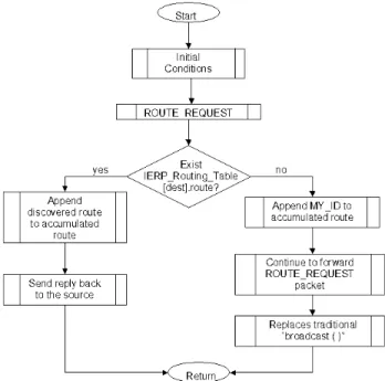
(48) 26. CHAPTER 4. SIMULATION OF ZRP. So when neighboring nodes in a route move out of direct contact radio, the resulting link failure interrupts data flow across the route. For a purely reactive routing protocol, any routes that include the broken link immediately fail. To maintain end-to-end connectivity, a new route discovery / repair would have to be initiated. Until a replacement route or route segment is discovered, incoming data packets are either delayed or dropped, degrading application performance. Because the routing zone provides a node with a view beyond its own neighborhood, many link failures can be instantly bypassed. As long as the former neighbor remains within the routing zone, incoming data packets can be redirected around a broken link, through an active multi-hop path for the former neighbor.. 4.4.1. IERP Implementation. According to [9], this example IERP demostrates the integration of bordercast route discovery and routing zone based route maintenance in a source route reactive routing protocol. When a node has no valid route to forward a data packet, it launches a route discovery, probing the network via bordercast ROUTE REQUEST packets. When a node receives a ROUTE REQUEST packet, it appends its IP address along with metrics for the link on which the packet was received. It then checks its Routing Tables for a valid route to the query destination. If no valid route is found, the node relays the ROUTE REQUEST to the “downstream” neighbors identified by the bordercast service (provided by the Bordercast Resolution Protocol (BRP)). If a valid route to the query destination is known, then the route is appended to the ROUTE REQUEST’s accumulated route. The complete route is copied to a ROUTE REPLY packet. The ROUTE REPLY is forwarded back to the query source, by IERP, along the reversed accumulated route. IERP also leverages the known routing zone topology to support local proactive route maintenance. When a node’s IARP detects a change in its routing zone connectivity, the IERP is notified and proceeds to review the status of its routes. For each IERP route, the node identifies an alternate path through its routing zone that minimizes the distance to the destination. This serves to bypass failed links and sub-optimal route segments. The updated routes are then saved in the IERP routing table, (see Table 4.2). Field Description of Figure 4.2: • Type : Identifies the type of IERP packet. The current version of IERP contains two packet types: • ROUTE REQUEST: Request for a route to the Query Destination. The ROUTE REQUEST records the path that it has travelled from the Query Source..
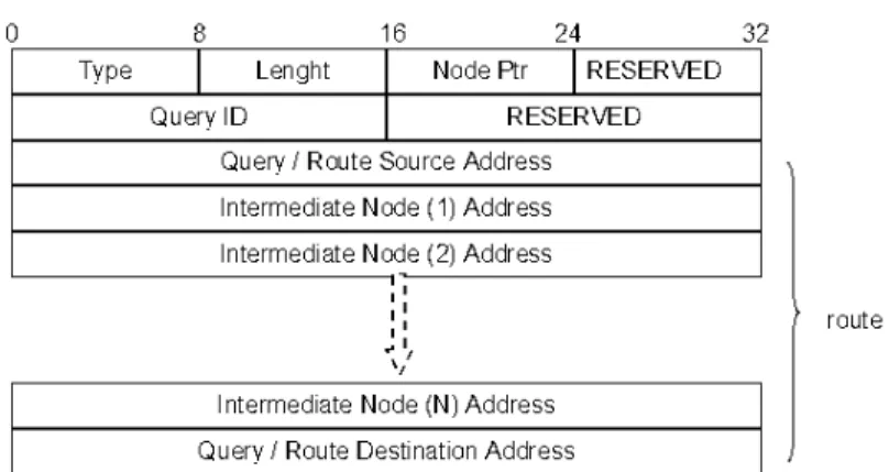
(49) 4.4. ROUTING ZONE BASED ROUTE MAINTENANCE. 27. Figure 4.2: Packet Format IERP • ROUTE REPLY: Response to a ROUTE REQUEST packet, issued by the node that discovers a route to the Query Destination, and sent back to the Query Source. • Length : Length of the packet, in multiples of 32 bit words. • Node Pointer : Index into the route corresponding to the node that has just received, or is next to receive, this packet. • Query ID : Sequence number which, along with the Query Source Address uniquely identifies any ROUTE REQUEST in the network. • Query/Route Source Address : IP address of the node that initiates the ROUTE REQUEST. In subsequent stages, this corresponds to the IP address of the discovered route’s source node. • Query/Route Destination Address : IP address to be located during the ROUTE REQUEST phase. In subsequent stages, this field contains the IP address of the discovered route’s destination node. • Route : Variable length field that contains the recorded IP addresses of nodes along the path travelled by this ROUTE REQUEST packet from the Query Source. After a route to the Query Destination has been discovered, this set of IP addresses provides a specification of the route between the Route Source and Route Destination. In table 4.2 the IERP Routing Table contains the destination address, the subnet mask, the route and route metrics items, which contain the information that IERP needs..
(50) 28. CHAPTER 4. SIMULATION OF ZRP. Table 4.2: Data Structure IERP. Dest Addr Subnet Mask (node id) (node id). 4.4.2. Route (node id list). Route Metrics (metric list). State Machine IERP. IERP consists of only single state (IDLE) [9]. Therefore, no state transitions need to be specified. IERP immediately acts upon an event and then returns back to the IDLE state. 1. IARP reports an update to routing zone connectivity. For each route in X’s IERP routing table, compute a path to each downstream node (based on the IARP routing table). Identify the computed path that minimizes the route length, and update the IERP route with this path. 2. A ROUTE REQUEST packet is received with a destination that appears within X’s routing zone. The packet’s accumulated route information (for the source) is recorded in X’s Routing Table and Temporary Query Cache. The accumulated route is replaced by X’s address and any accumulated route metrics are updated and compressed. X copies the ROUTE REQUEST packet’s contents to a ROUTE REPLY packet. The ROUTE REPLY packet is returned to the query source, along the reversed accumulated route. 3. A ROUTE REQUEST packet is received with a destination that DOES NOT appear within X’s routing zone. X adds its address to the accumulated route and the ROUTE REQUEST packet is bordercast(), (see Figure 4.3). 4. A ROUTE REPLY packet is received. The packet’s accumulated route information (for the destination) is recorded in X’s Routing Table. X adds its address to the accumulated route and adds metrics for the downstream (toward the destination) link to the accumulated metrics. If X is not the query source, then X forwards the message toward the source (directly through IP), along a path selected from the Temporary Query Cache (i.e., based on Diversity Injection), (see Figure 4.4)..
(51) 4.4. ROUTING ZONE BASED ROUTE MAINTENANCE. Figure 4.3: Flow chart for the Route Request. Figure 4.4: Flow chart for the Route Reply. 29.
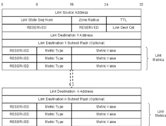
(52) 30. CHAPTER 4. SIMULATION OF ZRP. 4.4.3. IARP Implementation. Nodes compute intrazone routes based on the proactively tracked link state of each routing zone member. Each node periodically advertises its link state (current set of neighbors and corresponding lists of link metrics) throughout its routing zone. Nodes monitor their own link state by means of a neighbor discovery protocol. This IARP relies on the services of a separate protocol (referred to here as the Neighbor Discovery Protocol (NDP)) to provide current information about a node’s neighbors. At the least, this information must include the IP addresses of all the neighbors. IARP and NDP can be configured to support supplemental link quality metrics, [10]. The scope of a link state update is controlled by a TTL (time-to-live) value that is carried in the link state packet. The TTL is initialized by the link source to R-1 hops (where R is the zone radius). Upon receipt of link state update packet, the link state is recorded, the routing table is recomputed and the TTL packet’s value is decremented. As long as the TTL value is greater than 0, the link state update packet is rebroadcast.. Figure 4.5: Packet Format IARP The description field of Packet Format IARP is shown in Figure 4.5: • Link Source Address: IP address of the reported link’s source node. • Link State Seq : Sequence number used to track the link state history of the Source node Link. • Zone Radius : Routing zone radius of the link’s source node. Determines the extent that link state information propagates. • TTL : number of hops remaining until packet is to be discarded..
Figure
+7
Documento similar
In the previous chapters, APR was proposed as a potential route for valorisation and treatment of brewery wastewater, and although good results in terms of removal of organic
Suppose the algorithm was properly applied and it ended by giving the destination vertex a number N, implying the shortest route is N units long, but that there exists a
Chapter 4 “Performance Evaluation of 802.11g Mobile Ad-hoc Networks Supporting Multimedia Traffic: a QoE Perspective” compares two well-known ad- hoc routing
• For those nodes and (mobile) routers with standard MIPv6 support, an address delegation mechanism, based on protocol for carrying authentication for network access (PANA) [15]
In this arti- cle we explore different approaches to Route Optimisation in NEMO and we devise how to adapt some of the Termi- nal Mobility solutions to a NEMO environment, where, as
The rest of the paper is structured as follows: in section II the proposed solution (MIRON) is presented in detail, both for the case of a single NEMO and its extension to
basic network mobility support, as defined by the IETF in the RFC 3963; Route Optimisation support mitigating the effects of the sub-optimal routing introduced by the NEMO Basic
This paper presents an architecture that combines enhanced Network Mobility mechanisms - to provide transparent and route optimised mobility support for roaming networks -
