EC 1251 Guía Thevenin And Norton pdf
36
0
0
Texto completo
(2) determine a requested quantity. The Th¶evenin equivalent method can be broken into the following steps: 1. First calculate the open-circuit voltage. Draw the circuit with the load resistor removed, which creates an open circuit where the resistor once was. Label this circuit with + and ¡ polarity markings and the symbol voc . Then use any circuit analysis technique to determine the value of voc . In the examples we will usually use the mesh current method or the node voltage method. 2. Next calculate the Th¶evenin equivalent resistance if the circuit contains only independent sources and resistors, or the short-circuit current if the circuit also contains dependent sources. To calculate the Th¶evenin equivalent resistance, draw the circuit with the load resistor removed. From the perspective of the resulting open circuit, calculate the equivalent resistance. To do this, replace all voltage sources with short circuits and all current sources with open circuits. Then make series and parallel combinations of the remaining resistors until only one resistor remains. This is the Th¶evenin equivalent resistor. If there are dependent sources in the circuit, you cannot use the previous method to calculate the Th¶evenin equivalent resistance because you cannot remove the independent sources without changing the way the dependent sources behave. Therefore you must calculate the short-circuit current instead. To do this, draw the circuit the the load resistor removed and replaced by a short circuit (a wire). Label the current in the short circuit isc . Then use any circuit analysis technique to determine the value of isc . We usually employ the node voltage method or the mesh current method. Remember that we can use the open-circuit voltage and the short-circuit current to determine the Th¶evenin equivalent resistance with the equation voc : RTh = isc 3. Now draw the Th¶evenin equivalent circuit, which consists of a voltage source with the value voc in series with a resistor whose value is RTh , or the Norton equivalent circuit, which consists of a current source with the value isc in parallel with a resistor whose value is RTh . Then attach the original load resistor to complete the circuit. Use any circuit analysis method to determine the requested voltage, current or power in this simpli¯ed circuit. 4. You can check your result by analyzing the original circuit using any appropriate circuit analysis technique. We will usually employ the node voltage method or the mesh current method. The ¯rst example is a circuit without dependent sources. We consider circuits with dependent sources in the second example. 2.
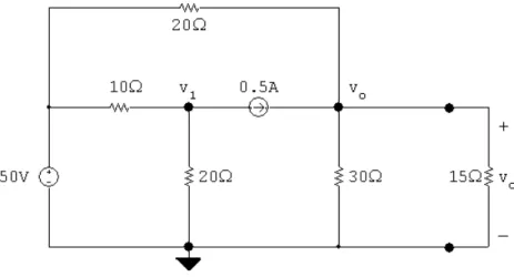
(3) Figure 1: The circuit for Th¶evenin Equivalent Example 1. Figure 2: The circuit for Th¶evenin Equivalent Example 1, con¯gured to determine the open-circuit voltage voc .. Th¶ evenin Equivalent Example 1 Find vo for the circuit in Fig. 1 by replacing the circuit to the left of the 15− resistor with its Th¶evenin equivalent and analyzing the resulting simpli¯ed circuit.. Solution 1. Redraw the circuit in Fig. 1 with the 15− resistor replaced by an open circuit labeled voc and calculate the value of voc . We will use the node voltage method to determine voc , so we have identi¯ed the reference node and labeled the remaining non-reference essential nodes with symbols if the voltage at the node is not known. The resulting circuit is shown in Fig. 2. The node voltage equations are. 3.
(4) Figure 3: The circuit for Th¶evenin Equivalent Example 1, con¯gured to determine the Th¶evenin equivalent resistance RTh . At v1 :. v1 ¡ 50 v1 + + 0:5 10 20. At voc :. voc ¡ 50 voc + ¡ 0:5 = 0 20 30. = 0. Rewriting the node voltage equations in standard form we get At v1 : At voc :. µ. ¶. 1 1 + v1 + (0)voc = (50=10) ¡ 0:5 10 20 µ ¶ 1 1 + (0)v1 + voc = (50=20) + 0:5 20 30. The calculator solution is voc = 36 V.. v1 = 30 V;. 2. Since there are no dependent sources in the circuit in Fig. 1 we can calculate the Th¶evenin equivalent resistance. To do this, redraw the circuit in Fig. 1, replacing the 15− resistor with an open circuit, the current source with an open circuit, and the voltage source with a short circuit. The resulting circuit is shown in Fig. 3. Notice that in Fig. 3 the 10− and 20− resistors in the lower left have been bypassed by a short circuit, and that the remaining 20− and 30− resistors are in parallel. Therefore, the equivalent resistance is given by RTh = 20k30 =. (20)(30) = 12−: 20 + 30. 3. Now draw the Th¶evenin equivalent circuit and attach the 15− resistor. The result is shown in Fig. 4. To ¯nd vo in this simple circuit, use voltage division: 15 (36) = 20 V vo = 15 + 12. 4.
(5) Figure 4: The circuit for Th¶evenin Equivalent Example 1, with the components to the left of the 15− resistor replaced by a Th¶evenin equivalent.. Figure 5: The circuit for Th¶evenin Equivalent Example 1, prepared for node voltage analysis. 4. We can check this result by analyzing the original circuit in Fig. 1 to ¯nd vo . We choose the node voltage method for this analysis, and the circuit in Fig. 5 is con¯gured for such analysis. The node voltage equations are v1 ¡ 50 v1 + + 0:5 10 20. At v1 : At vo :. = 0. vo vo ¡ 50 vo + + ¡ 0:5 = 0 20 30 15. Rewriting the node voltage equations in standard form we get At v1 : At vo :. µ. ¶. 1 1 v1 + (0)voc = (50=10) ¡ 0:5 + 10 20 µ ¶ 1 1 1 (0)v1 + + + = (50=20) + 0:5 20 30 15. The calculator solution is vo = 20 V.. v1 = 30 V;. Thus the solution obtained with the Th¶evenin equivalent circuit is con¯rmed. 5.
(6) Figure 6: The circuit for Th¶evenin Equivalent Example 2. Figure 7: The circuit for Th¶evenin Equivalent Example 1, con¯gured to determine the open-circuit voltage voc .. Th¶ evenin Equivalent Example 2 Find io for the circuit in Fig. 6 by replacing the circuit to the left of the 4− resistor with its Norton equivalent and analyzing the resulting simpli¯ed circuit.. Solution 1. Redraw the circuit in Fig. 6 with the 4− resistor replaced by an open circuit labeled voc and calculate the value of voc . We will use the node voltage method to determine voc , so we have identi¯ed the reference node. The remaining non-reference essential nodes form a single supernode with the dependent source, so we label those nodes with symbols and identify the suprenode. The resulting circuit is shown in Fig. 7. The node voltage analysis equations consist of one supernode equation and two constraint equations, one for the supernode and one for the dependent source. The equations are Supernode:. v1 ¡ 50 v1 voc + + = 2 6 2. Constraint:. v1 ¡ voc. Constraint:. v1 6 6. 0. = 4ix =. ix.
(7) Figure 8: The circuit for Th¶evenin Equivalent Example 2, con¯gured to determine the short-circuit current isc . Rewriting the node voltage equations in standard form we get Supernode:. µ. Constraint: Constraint:. ¶. µ ¶. 1 1 1 + v1 + voc + (0)ix = (50=2) 2 6 2 (1)v + (¡1)voc + (¡4)ix = 0 µ ¶1 1 v1 + (0)voc + (¡1)ix = 0 6. The calculator solution is v1 = 30 V;. voc = 10 V;. ix = 5 A.. 2. Since there is a dependent source in the circuit in Fig. 6 we must calculate the short-circuit current. To do this, redraw the circuit in Fig. 6, replacing the 4− resistor with short circuit and label the current in the short circuit isc . Since we want to ¯nd this short-circuit current the mesh current method is a good choice, so we also identify and label the mesh currents. The resulting circuit is shown in Fig. 8. We need three mesh current equations and a constraint equation for the dependent source. The equations are The equations are Left mesh: ¡50 + 8i1 + 6(i1 ¡ i2 ) Center mesh: 4ix + 2(i2 ¡ isc ) + 6(i2 ¡ i1 ) Right mesh: 3:6isc + 2(isc ¡ i2 ) Constraint: i1 ¡ i2. = 0 = 0 = 0 = ix. Rewriting the mesh current equations in standard form we get Left mesh: (8)i1 Center mesh: (¡6)i1 Right mesh: (0)i1 Constraint: (1)i1. + (¡6)i2 + (8)i2 + (¡2)i2 + (¡1)i2. + (0)isc + (¡2)isc + (5:6)isc + (0)isc. + (0)ix + (4)ix + (0)ix + (¡1)ix. = 50 = 0 = 0 = 0. The calculator solution is i1 = 11:5 A;. i2 = 7 A; 7. isc = 2:5 A;. ix = 4:5 A..
(8) Figure 9: The circuit for Th¶evenin Equivalent Example 2, with the components to the left of the 4− resistor replaced by a Norton equivalent.. Figure 10: The circuit for Th¶evenin Equivalent Example 2, prepared for mesh current analysis. 3. Now draw the Norton equivalent circuit by placing a current source whose value is isc = 2:5A in parallel with a resistor whose value is rTh = voc =isc = 10=2:5 = 4−, attach the 4− load resistor. The result is shown in Fig. 9. To ¯nd io in this simple circuit, use current division: io =. 4 (2:5) = 1:25 A 4+4. 4. We can check this result by analyzing the original circuit in Fig. 6 to ¯nd io . We choose the mesh current method for this analysis, and the circuit in Fig. 10 is con¯gured for such analysis. We need three mesh current equations and one constraint equation, as shown below: Left mesh: ¡50 + 8i1 + 6(i1 ¡ i2 ) Center mesh: 4ix + 2(i2 ¡ io ) + 6(i2 ¡ i1 ) Right mesh: 3:6io + 4io + 2(io ¡ i2 ) Constraint: i1 ¡ i2. = 0 = 0 = 0 = ix. Rewriting the mesh current equations in standard form we get Left mesh: (8)i1 Center mesh: (¡6)i1 Right mesh: (0)i1 Constraint: (1)i1. + (¡6)i2 + (8)i2 + (¡2)i2 + (¡1)i2. + (0)io + (¡2)io + (9:6)io + (0)io. + (0)ix + (4)ix + (0)ix + (¡1)ix. = 50 = 0 = 0 = 0. The calculator solution is i1 = 10:75 A;. i2 = 6 A; 8. io = 1:25 A;. ix = 4:75 A..
(9) Thus the solution obtained with the Norton equivalent circuit is con¯rmed. Now try using the Th¶evenin equivalent method for each of the practice problems below.. 9.
(10) Figure 11: The circuit for Th¶evenin Equivalent Practice Problem 1.. Th¶ evenin Equivalent Practice Problem 1 Find vo for the circuit in Fig. 11 by replacing the circuit to the left of the 36− resistor with its Th¶evenin equivalent. 1. Redraw the circuit in Fig. 11, replacing the 36− resistor with an open circuit. Use this circuit to calculate voc .. 10.
(11) 2. Are there dependent sources in the circuit? If not, ¯nd the Th¶evenin equivalent resistor by redrawing the circuit in Fig. 11 with the load resistor removed, the voltage sources replaced by short circuits, and the current sources replaced with open circuits. Then make series and parallel combinations of resistors until a single equivalent resistor remains. If there are dependent sources in the circuit, ¯nd the short circuit current by redrawing the circuit in Fig. 11, replacing the 36− resistor with a short circuit whose current is isc . Use this circuit to ¯nd isc .. 3. Draw the Th¶evenin equivalent circuit and attach the 36− resistor. Use this circuit to calculate vo .. 11.
(12) 4. Check your solution by analyzing the original circuit in Fig. 11 to ¯nd vo .. 12.
(13) Figure 12: The circuit for Th¶evenin Equivalent Practice Problem 2.. Th¶ evenin Equivalent Practice Problem 2 Find io for the circuit in Fig. 12 by replacing the circuit to the left of the 3− resistor with its Norton equivalent. 1. Redraw the circuit in Fig. 12, replacing the 3− resistor with an open circuit. Use this circuit to calculate voc .. 13.
(14) 2. Are there dependent sources in the circuit? If not, ¯nd the Th¶evenin equivalent resistor by redrawing the circuit in Fig. 12 with the load resistor removed, the voltage sources replaced by short circuits, and the current sources replaced with open circuits. Then make series and parallel combinations of resistors until a single equivalent resistor remains. If there are dependent sources in the circuit, ¯nd the short circuit current by redrawing the circuit in Fig. 12, replacing the load resistor with a short circuit whose current is isc . Use this circuit to ¯nd isc .. 3. Draw the Norton equivalent circuit and attach the 3− resistor. Use this circuit to calculate io .. 14.
(15) 4. Check your solution by analyzing the original circuit in Fig. 12 to ¯nd io .. 15.
(16) Figure 13: The circuit for Th¶evenin Equivalent Practice Problem 3.. Th¶ evenin Equivalent Practice Problem 3 Find vo for the circuit in Fig. 13 by replacing the circuit to the left of the 16− resistor with its Th¶evenin equivalent. 1. Redraw the circuit in Fig. 13, replacing the 16− resistor with an open circuit. Use this circuit to calculate voc .. 16.
(17) 2. Are there dependent sources in the circuit? If not, ¯nd the Th¶evenin equivalent resistor by redrawing the circuit in Fig. 13 with the load resistor removed, the voltage sources replaced by short circuits, and the current sources replaced with open circuits. Then make series and parallel combinations of resistors until a single equivalent resistor remains. If there are dependent sources in the circuit, ¯nd the short circuit current by redrawing the circuit in Fig. 13, replacing the load resistor with a short circuit whose current is isc . Use this circuit to ¯nd isc .. 3. Draw the Th¶evenin equivalent circuit and attach the 16− resistor. Use this circuit to calculate vo .. 17.
(18) 4. Check your solution by analyzing the original circuit in Fig. 13 to ¯nd vo .. 18.
(19) Figure 14: The circuit for Th¶evenin Equivalent Practice Problem 4.. Th¶ evenin Equivalent Practice Problem 4 Find power dissipated in the 40− resistor for the circuit in Fig. 14 by replacing the circuit to the left of the 40− resistor with its Th¶evenin equivalent. 1. Redraw the circuit in Fig. 14, replacing the 40− resistor with an open circuit. Use this circuit to calculate voc .. 19.
(20) 2. Are there dependent sources in the circuit? If not, ¯nd the Th¶evenin equivalent resistor by redrawing the circuit in Fig. 14 with the load resistor removed, the voltage sources replaced by short circuits, and the current sources replaced with open circuits. Then make series and parallel combinations of resistors until a single equivalent resistor remains. If there are dependent sources in the circuit, ¯nd the short circuit current by redrawing the circuit in Fig. 14, replacing the load resistor with a short circuit whose current is isc . Use this circuit to ¯nd isc .. 3. Draw the Th¶evenin equivalent circuit and attach the 40− resistor. Use this circuit to calculate the power dissipated by this 40− resistor.. 20.
(21) 4. Check your solution by analyzing the original circuit in Fig. 14 to ¯nd p40− .. 21.
(22) Figure 15: The circuit for Th¶evenin Equivalent Practice Problem 5.. Th¶ evenin Equivalent Practice Problem 5 Find vo for the circuit in Fig. 15 by replacing the circuit to the left of the 16− resistor with its Th¶evenin equivalent. 1. Redraw the circuit in Fig. 15, replacing the 16− resistor with an open circuit. Use this circuit to calculate voc .. 22.
(23) 2. Are there dependent sources in the circuit? If not, ¯nd the Th¶evenin equivalent resistor by redrawing the circuit in Fig. 15 with the load resistor removed, the voltage sources replaced by short circuits, and the current sources replaced with open circuits. Then make series and parallel combinations of resistors until a single equivalent resistor remains. If there are dependent sources in the circuit, ¯nd the short circuit current by redrawing the circuit in Fig. 15, replacing the load resistor with a short circuit whose current is isc . Use this circuit to ¯nd isc .. 3. Draw the Th¶evenin equivalent circuit and attach the 16− resistor. Use this circuit to calculate vo .. 23.
(24) 4. Check your solution by analyzing the original circuit in Fig. 15 to ¯nd vo .. 24.
(25) Figure 16: The circuit for Th¶evenin Equivalent Practice Problem 6.. Th¶ evenin Equivalent Practice Problem 6 Find the power dissipated in the 100− resistor for the circuit in Fig. 16 by replacing the circuit to the left of the 100− resistor with its Th¶evenin equivalent. 1. Redraw the circuit in Fig. 16, replacing the 100− resistor with an open circuit. Use this circuit to calculate voc .. 25.
(26) 2. Are there dependent sources in the circuit? If not, ¯nd the Th¶evenin equivalent resistor by redrawing the circuit in Fig. 16 with the load resistor removed, the voltage sources replaced by short circuits, and the current sources replaced with open circuits. Then make series and parallel combinations of resistors until a single equivalent resistor remains. If there are dependent sources in the circuit, ¯nd the short circuit current by redrawing the circuit in Fig. 16, replacing the load resistor with a short circuit whose current is isc . Use this circuit to ¯nd isc .. 3. Draw the Th¶evenin equivalent circuit and attach the 100− resistor. Use this circuit to calculate the power dissipated in this resistor.. 26.
(27) 4. Check your solution by analyzing the original circuit in Fig. 16 to ¯nd p100− .. 27.
(28) Figure 17: The circuit for Th¶evenin Equivalent Practice Problem 7.. Th¶ evenin Equivalent Practice Problem 7 Find vo for the circuit in Fig. 17 by replacing the circuit to the left of the 250− resistor with its Th¶evenin equivalent. 1. Redraw the circuit in Fig. 17, replacing the 250− resistor with an open circuit. Use this circuit to calculate voc .. 28.
(29) 2. Are there dependent sources in the circuit? If not, ¯nd the Th¶evenin equivalent resistor by redrawing the circuit in Fig. 17 with the load resistor removed, the voltage sources replaced by short circuits, and the current sources replaced with open circuits. Then make series and parallel combinations of resistors until a single equivalent resistor remains. If there are dependent sources in the circuit, ¯nd the short circuit current by redrawing the circuit in Fig. 17, replacing the load resistor with a short circuit whose current is isc . Use this circuit to ¯nd isc .. 3. Draw the Th¶evenin equivalent circuit and attach the 250− resistor. Use this circuit to calculate vo .. 29.
(30) 4. Check your solution by analyzing the original circuit in Fig. 17 to ¯nd vo .. 30.
(31) Figure 18: The circuit for Th¶evenin Equivalent Practice Problem 8.. Th¶ evenin Equivalent Practice Problem 8 Find io for the circuit in Fig. 18 by replacing the circuit to the left of the 80− resistor with its Norton equivalent. 1. Redraw the circuit in Fig. 18, replacing the 80− resistor with an open circuit. Use this circuit to calculate voc .. 31.
(32) 2. Are there dependent sources in the circuit? If not, ¯nd the Th¶evenin equivalent resistor by redrawing the circuit in Fig. 18 with the load resistor removed, the voltage sources replaced by short circuits, and the current sources replaced with open circuits. Then make series and parallel combinations of resistors until a single equivalent resistor remains. If there are dependent sources in the circuit, ¯nd the short circuit current by redrawing the circuit in Fig. 18, replacing the load resistor with a short circuit whose current is isc . Use this circuit to ¯nd isc .. 3. Draw the Norton equivalent circuit and attach the 80− resistor. Use this circuit to calculate io .. 32.
(33) 4. Check your solution by analyzing the original circuit in Fig. 18 to ¯nd io .. 33.
(34) Reading ² in Introductory Circuits for Electrical and Computer Engineering: { Section 3.9 | Th¶evenin and Norton equivalents { Section 3.10 | more Th¶evenin and Norton equivalents ² in Electric Circuits, sixth edition: { Section 4.10 | Th¶evenin and Norton equivalents { Section 4.11 | more Th¶evenin and Norton equivalents ² Workbook section | Node Voltage Method ² Workbook section | Mesh Current Method. Additional Problems ² in Introductory Circuits for Electrical and Computer Engineering: { 3.50 | 3.56 { 3.58 ² in Electric Circuits, sixth edition: { 4.58 | 4.62 { 4.66 { 4.69 | 4.70. Solutions ² Th¶evenin Equivalent Practice Problem 1: voc = 3:75 V. isc = 208:33 mA. RTh = 18−. vo = 2:5 V.. ² Th¶evenin Equivalent Practice Problem 2: voc = 10 V. isc = 5 A. RTh = 2−. io = 2 A.. ² Th¶evenin Equivalent Practice Problem 3: voc = 105 V. isc = 13:125 A. RTh = 8−. vo = 70 V.. ² Th¶evenin Equivalent Practice Problem 4: voc = 250 V. isc = 25 A 34. RTh = 10−. p40− = 1 kW..
(35) ² Th¶evenin Equivalent Practice Problem 5: voc = ¡20 V. isc = ¡1:25 A. RTh = 16−. vo = ¡10 V.. ² Th¶evenin Equivalent Practice Problem 6: voc = 75 V. isc = 1:5 A. RTh = 50−. p100− = 25 W.. ² Th¶evenin Equivalent Practice Problem 7: voc = 125 V. isc = 2 A. RTh = 62:5−. vo = 100 V.. ² Th¶evenin Equivalent Practice Problem 8: voc = 120 V. isc = 3 A. 35. RTh = 40−. io = 1 A..
(36)
(37)
Figure


+7


Documento similar
The general idea of the language is to “thread together,” so to speak, existing systems that parse and analyze single web pages into a navigation procedure spanning several pages of
The spinach yield was significantly higher in both CT treatments (CT and CT + Th) than in the control in both experiments (early and late winter) (Figure 1a, Table 2).. The CT +
An employee who sleeps 8 hours per night may still have poor sleep quality, preventing the individual from showing up for work at peak performance.. Additionally, sleep hygiene
The general objective of this study is developing and implementing a simple method, based on spatially explicit linear regressions, that allows to obtain an estimate of the
Abstract: We propose a rigorous and effective way to compare experimental and theoret- ical histograms, incorporating the different sources of statistical and systematic
The Green’s func- tions associated with planar excitations are briefly recalled, and the method to compute them is generalized to vertical current sources, yielding new components
Citrons inoculated with different field sources, displayed a variety of symptoms ranging from very mild leaf bending and necrosis to the severe reaction
In the preparation of this report, the Venice Commission has relied on the comments of its rapporteurs; its recently adopted Report on Respect for Democracy, Human Rights and the Rule
