Design and Implementation of a Remote Electronics Laboratory in Real Time Edición Única
107
0
0
Texto completo
(2) INSTITUTO TECNOLÓGICO DE ESTUDIOS SUPERIORES DE MONTERREY INFORMATION TECHNOLOGY AND ELECTRONICS DIVISION GRADUATE PROGRAM IN INFORMATION TECHNOLOGY AND ELECTRONICS. The members of this thesis committee recommend that the present thesis from Ing. Israel Méndez Galván be accepted in partial fulfillment for the requirements for the degree of Master of Science in Electronics Engineering with specialty in Electronic Systems. Thesis Commitee:. ______________________________ Dr. Manuel E. Macías Advisor. ______________________________ Dr. Alfonso Ávila First Reader. ______________________________ M.S. Ricardo Guzmán Second Reader. _________________________________________ Dr. Graciano Dieck Assad Director of the Graduate Program in Information Technology and Electronics August 2007.
(3) To my parents, Germán and Dora. To my brothers, Fabián and Debanhi. To all my family and friends.. iii.
(4) ACKNOWLEDGEMENTS. I want to thank my thesis advisor, Dr. Manuel Macías, for all of his help and support during the completion of this thesis and throughout my master studies, for sharing his knowledge and letting me grow professionally and as a person. Also, for his patience, for believing in this project, and for helping me accomplish this dream. I would also like to acknowledge the vast help of my thesis readers, Dr. Alfonso Ávila and M.S. Ricardo Guzmán, whose valuable comments and corrections helped me develop a more complete and polished document. The time they took from their schedule to review my thesis is greatly appreciated. To my family, all I can say is "Thank you".. Thank you, mom and dad, for. understanding and supporting me throughout this important phase in my career, for inspiring me.. Thank you, my brothers, for putting up with my craziness and,. unwillingly and maybe unknowingly, providing me with inspiration.. Thank you,. grandma, for being there when me and my family need you, and for being the greatest grandma anyone could ask for. Thank you great-aunts, for helping us, for supporting us, for being there. Güeli, I know you watch over us and feel proud of me; wherever you are, a special thank you to the foundation of this entire family. My friends, who are always there for me for better or for worse. Thank you for being a great part of my life and encouraging me. My classmates and friends, my coworkers at "The Cave". I know you have a hard time putting up with me sometimes, but nonetheless, you’ve done it and made my way through these two years a breeze. Thank you. Finally, I would also like to acknowledge the help and support of the Electrical and Computing Engineering Department at ITESM Campus Monterrey for their continuous support, and to the Consejo Nacional de Ciencia y Tecnología.. iv.
(5) TABLE OF CONTENTS DEDICATION . . . . . . . . . . . . . . . . . . . . . . . . . . . . . . . . . .. iii. ACKNOWLEDGEMENTS . . . . . . . . . . . . . . . . . . . . . . . . . .. iv. LIST OF TABLES. . . . . . . . . . . . . . . . . . . . . . . . . . . . . . . . viii . . . . . . . . . . . . . . . . . . . . . . . . . . . . . .. ix. SUMMARY . . . . . . . . . . . . . . . . . . . . . . . . . . . . . . . . . . . .. xii. INTRODUCTION . . . . . . . . . . . . . . . . . . . . . . . . . . . . .. 1. 1.1 Problem Statement . . . . . . . . . . . . . . . . . . . . . . . . . . .. 2. 1.2 Thesis Statement . . . . . . . . . . . . . . . . . . . . . . . . . . . .. 3. 1.3 Methodology . . . . . . . . . . . . . . . . . . . . . . . . . . . . . . .. 4. 1.4 Overview . . . . . . . . . . . . . . . . . . . . . . . . . . . . . . . . .. 6. ANTECEDENTS . . . . . . . . . . . . . . . . . . . . . . . . . . . . . .. 7. 2.1 Remote Laboratories Around The World . . . . . . . . . . . . . . .. 10. 2.2 Laboratory Comparison . . . . . . . . . . . . . . . . . . . . . . . . .. 19. LIST OF FIGURES. I. II. 2.2.1. Interface Technology . . . . . . . . . . . . . . . . . . . . . . .. 19. 2.2.2. Laboratory Equipment Cost . . . . . . . . . . . . . . . . . .. 22. 2.2.3. Access Implementation . . . . . . . . . . . . . . . . . . . . .. 22. 2.2.4. Experimentation Process . . . . . . . . . . . . . . . . . . . .. 24. III SYSTEM ARCHITECTURE . . . . . . . . . . . . . . . . . . . . . .. 26. 3.1 Architectural Elements . . . . . . . . . . . . . . . . . . . . . . . . .. 27. 3.1.1. Remote User (Client) . . . . . . . . . . . . . . . . . . . . . .. 27. 3.1.2. Scheduling System Database Server . . . . . . . . . . . . . .. 28. 3.1.3. Access Server . . . . . . . . . . . . . . . . . . . . . . . . . .. 28. 3.1.4. Web Server . . . . . . . . . . . . . . . . . . . . . . . . . . . .. 29. 3.1.5. Practice Station . . . . . . . . . . . . . . . . . . . . . . . . .. 31. 3.2 Connection Schemes . . . . . . . . . . . . . . . . . . . . . . . . . . .. 33. v.
(6) 3.2.1. Low-Cost Implementation . . . . . . . . . . . . . . . . . . . .. 33. 3.2.2. High-Performance Implementation . . . . . . . . . . . . . . .. 35. 3.2.3. Choosing a Connection Scheme . . . . . . . . . . . . . . . . .. 36. IV SCHEDULING SYSTEM . . . . . . . . . . . . . . . . . . . . . . . . .. 40. 4.1 Database Structure . . . . . . . . . . . . . . . . . . . . . . . . . . .. 40. 4.2 Scheduling System Webpages . . . . . . . . . . . . . . . . . . . . . .. 43. PRACTICE STATION . . . . . . . . . . . . . . . . . . . . . . . . . .. 51. 5.1 Practice Interface . . . . . . . . . . . . . . . . . . . . . . . . . . . .. 51. V. 5.1.1. Practice Login . . . . . . . . . . . . . . . . . . . . . . . . . .. 53. 5.1.2. Practice-Speci…c Interface . . . . . . . . . . . . . . . . . . . .. 56. 5.2 Data Acquisition Station . . . . . . . . . . . . . . . . . . . . . . . .. 65. 5.3 Implemented Practices . . . . . . . . . . . . . . . . . . . . . . . . .. 68. 5.3.1. Diode Practices . . . . . . . . . . . . . . . . . . . . . . . . .. 68. 5.3.2. Transistor Practices . . . . . . . . . . . . . . . . . . . . . . .. 69. VI USAGE ANALYSIS . . . . . . . . . . . . . . . . . . . . . . . . . . . .. 72. 6.1 Common Practice Weeks . . . . . . . . . . . . . . . . . . . . . . . .. 72. 6.1.1. Week 1 . . . . . . . . . . . . . . . . . . . . . . . . . . . . . .. 72. 6.1.2. Week 2 . . . . . . . . . . . . . . . . . . . . . . . . . . . . . .. 74. 6.2 Special Weeks . . . . . . . . . . . . . . . . . . . . . . . . . . . . . .. 76. 6.2.1. First Practice Week . . . . . . . . . . . . . . . . . . . . . . .. 76. 6.2.2. Special Events . . . . . . . . . . . . . . . . . . . . . . . . . .. 78. 6.3 General Analysis and Prediction . . . . . . . . . . . . . . . . . . . .. 81. 6.3.1. Result Validation . . . . . . . . . . . . . . . . . . . . . . . .. 83. VII CONCLUDING REMARKS . . . . . . . . . . . . . . . . . . . . . . .. 85. 7.1 eLab Advantages . . . . . . . . . . . . . . . . . . . . . . . . . . . . .. 86. 7.2 Future Development . . . . . . . . . . . . . . . . . . . . . . . . . . .. 88. 7.2.1. Design Practices . . . . . . . . . . . . . . . . . . . . . . . . .. 88. 7.2.2. High-Performance Implementation . . . . . . . . . . . . . . .. 88. vi.
(7) 7.2.3. High-Volume Implementation . . . . . . . . . . . . . . . . . .. 90. 7.2.4. Application to di¤erent areas . . . . . . . . . . . . . . . . . .. 91. REFERENCES . . . . . . . . . . . . . . . . . . . . . . . . . . . . . . . . . .. 93. VITA . . . . . . . . . . . . . . . . . . . . . . . . . . . . . . . . . . . . . . . .. 96. vii.
(8) LIST OF TABLES 1. Laboratory Interface Technology Comparison . . . . . . . . . . . . . .. 19. 2. Alternate Programming Language Comparison . . . . . . . . . . . . .. 20. 3. Connectivity Module Programming Comparison . . . . . . . . . . . .. 22. 4. Laboratory Equipment Comparison . . . . . . . . . . . . . . . . . . .. 22. 5. Access Implementation Comparison . . . . . . . . . . . . . . . . . . .. 24. 6. Experimentaton Process Comparison . . . . . . . . . . . . . . . . . .. 25. 7. Laboratory Equipment Cost Comparison . . . . . . . . . . . . . . . .. 37. 8. Laboratory Time Availability Comparison . . . . . . . . . . . . . . .. 39. 9. (PCI/AT)-MIO-16E-1 Speci…cations. . . . . . . . . . . . . . . . . . .. 66. 10. Reservation Time Table Data . . . . . . . . . . . . . . . . . . . . . .. 81. viii.
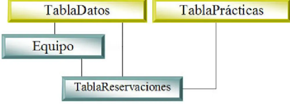
(9) LIST OF FIGURES 1. Proposed General Connection Scheme for Remote Laboratories . . . .. 5. 2. Di¤erent Online Courses . . . . . . . . . . . . . . . . . . . . . . . . .. 8. 3. Simulated Virtual Laboratory Diagram . . . . . . . . . . . . . . . . .. 9. 4. Remote Virtual Laboratory Diagram . . . . . . . . . . . . . . . . . .. 10. 5. iLab Architecture (Source: iLab Project) . . . . . . . . . . . . . . . .. 12. 6. iLab’s Interface Examples (Source: iLab Project) . . . . . . . . . . . .. 13. 7. Lab on The Web Architecture (Source: Lab On The Web report) . . .. 14. 8. Lab on The Web’s Interface Examples (Source: Lab on The Web report) 15. 9. Next Generation Lab Architecture (Source: NGL project) . . . . . . .. 16. 10. Next Generation Lab Interface Examples (Source: NGL Project) . . .. 17. 11. eLab’s Architecture . . . . . . . . . . . . . . . . . . . . . . . . . . . .. 18. 12. Graphical User Interface Comparison . . . . . . . . . . . . . . . . . .. 20. 13. eLab’s Home Page Overview . . . . . . . . . . . . . . . . . . . . . . .. 31. 14. eLab Domain Hierarchy . . . . . . . . . . . . . . . . . . . . . . . . .. 32. 15. Low-Cost Connection Scheme . . . . . . . . . . . . . . . . . . . . . .. 34. 16. High-Performance Connection Scheme . . . . . . . . . . . . . . . . .. 36. 17. "reservaciones" Database Table Hierarchy . . . . . . . . . . . . . . .. 41. 18. Scheduling System Webpage Hierarchy . . . . . . . . . . . . . . . . .. 44. 19. Scheduling System Login Page . . . . . . . . . . . . . . . . . . . . . .. 44. 20. Reservations System Webpage Overview . . . . . . . . . . . . . . . .. 45. 21. Date Selection Box . . . . . . . . . . . . . . . . . . . . . . . . . . . .. 46. 22. Reservation Information Box . . . . . . . . . . . . . . . . . . . . . . .. 47. 23. Team Information Box . . . . . . . . . . . . . . . . . . . . . . . . . .. 47. 24. Symbol Information Box . . . . . . . . . . . . . . . . . . . . . . . . .. 48. 25. Reservation Time Table . . . . . . . . . . . . . . . . . . . . . . . . .. 49. 26. Scheduling System Access Flow Chart . . . . . . . . . . . . . . . . .. 50. 27. Practice Interface Access Flow Chart . . . . . . . . . . . . . . . . . .. 52. ix.
(10) 28. Access Server Hierarchy for The Practice Interface . . . . . . . . . . .. 53. 29. Practice Login . . . . . . . . . . . . . . . . . . . . . . . . . . . . . . .. 54. 30. Practice Login’s Access Server Application . . . . . . . . . . . . . . .. 55. 31. Practice Interface Example for a Voltage Ampli…er . . . . . . . . . .. 57. 32. Practice-Speci…c Interface’s Access Server Application . . . . . . . . .. 59. 33. Circuit Diagram Section . . . . . . . . . . . . . . . . . . . . . . . . .. 60. 34. Frequency Generator Interface . . . . . . . . . . . . . . . . . . . . . .. 61. 35. Oscilloscope-like Display . . . . . . . . . . . . . . . . . . . . . . . . .. 61. 36. Practice Interface Example for a Clipping Circuit . . . . . . . . . . .. 63. 37. Practice Interface Example for Device Characterization . . . . . . . .. 65. 38. NI ELVIS . . . . . . . . . . . . . . . . . . . . . . . . . . . . . . . . .. 67. 39. Relay Switch Signal Attenuation by Frequency . . . . . . . . . . . . .. 68. 40. Reservation Time Table (Week 1) . . . . . . . . . . . . . . . . . . . .. 73. 41. Reservations Per Day (Week 1) . . . . . . . . . . . . . . . . . . . . .. 73. 42. Speci…c Workload for Week 1 . . . . . . . . . . . . . . . . . . . . . .. 74. 43. Reservation Time Table (Week 2) . . . . . . . . . . . . . . . . . . . .. 75. 44. Reservations Per Day (Week 2) . . . . . . . . . . . . . . . . . . . . .. 75. 45. Speci…c Workload for Week 2 . . . . . . . . . . . . . . . . . . . . . .. 76. 46. Reservation Time Table (First Week) . . . . . . . . . . . . . . . . . .. 77. 47. Reservations Per Day (First Week) . . . . . . . . . . . . . . . . . . .. 77. 48. Speci…c Workload for First Practice Week . . . . . . . . . . . . . . .. 78. 49. Reservation Time Table (Special Week) . . . . . . . . . . . . . . . . .. 79. 50. Reservations Per Day (Special Week) . . . . . . . . . . . . . . . . . .. 79. 51. Speci…c Workload for Special Week . . . . . . . . . . . . . . . . . . .. 80. 52. Day-by-day Total Workload . . . . . . . . . . . . . . . . . . . . . . .. 81. 53. Speci…c Workload Distribution . . . . . . . . . . . . . . . . . . . . . .. 82. 54. Average Laboratory Usage Per Day . . . . . . . . . . . . . . . . . . .. 82. 55. Average Time Distribution . . . . . . . . . . . . . . . . . . . . . . . .. 83. 56. Reservation Time Table (Di¤erent Semester) . . . . . . . . . . . . . .. 84. x.
(11) 57. Reservations Per Day (Di¤erent Semester) . . . . . . . . . . . . . . .. 84. 58. High-Performance Connection Scheme . . . . . . . . . . . . . . . . .. 89. 59. High-Volume Connection Scheme . . . . . . . . . . . . . . . . . . . .. 91. xi.
(12) SUMMARY. The ongoing integration of telecommunications with the learning and collaboration process has enabled many of the engineering projects to take advantage of the remote access to laboratories that it allows. However, since access is carried out remotely, it introduces a new need for remote laboratories which does not exactly exist in traditional labs: a scheduling system. In traditional laboratories, practices are developed and planned for a …xed number of hours a week, and students are also given …xed schedules for the entire semester. In remote laboratories, however, in order to achieve access ‡exibility and to allow the student to choose speci…c and di¤erent times for each practice, a scheduling system is required. The present thesis establishes a connection scheme, and a scheduling system for real, remote laboratories based in data acquisition (DAQ) systems, reducing the needed space for traditional Electronics laboratories, the sta¤ needed to operate it, and the overall cost of equipment required, as well as being remotely accessed through Internet with results and changes made to the circuit re‡ected in the measurements in real time, and freely scheduled for each user. Also, the focus of this work has been to develop a remote laboratory with real-time system response, which gives the user a better experience of the laboratory, retaining more of the qualities from a traditional one.. xii.
(13) CHAPTER I INTRODUCTION The accelerated pace at which both the computing and telecommunications worlds are advancing, along with their ever increasing availability, is creating a new relationship between the teaching process and the way students are learning, thus revolutionizing the way this process is carried out altogether. The development of distributed resources has modi…ed the traditional way to teach entirely, no longer restricting education to classrooms and libraries. So, we are bombarded with a countless number of tutorials, online courses, information pages, and network resources almost entirely devoted to the transmission of knowledge. However, the real and practical experience cannot be excluded from this process since it would have a negative impact in the learning process. Likewise, collaborative work and at-a-distance projects are beginning to have more attention in the Engineering world. With the integration of telecommunication technologies and computer science with virtual instrumentation, real, remote laboratories can be developed and accessed through Internet in real time, ensuring a richer collaborative experience for the student while avoiding some of the growing limitations of traditional laboratories, such as the lack of enough work area, expensive instrumentation, lack of personnel, time assigned to a laboratory, and their availability in non-working o¢ ce hours. To be able to connect the virtual and remote world with a real experiment, advantage can be taken from today’s Data Acquisition (DAQ) equipment and their ability to provide a development benchtop for measuring and instrumentation that can be easily connected, controlled, and processed with specialized software. Once a workstation has been connected to a computer, it can be easily controlled with virtual instruments created with the software which, at the same time, can be published into the network and be, not only accessed, but also controlled via Internet, allowing for the lab application to be used from any network connection. In the scheme implemented in the present thesis, various circuits and experiments were built on the DAQ station, such as power sources, voltage ampli…ers, device characterization circuits, and …lters; depending on the speci…c needs of each circuit, a connection to a function generator, variable voltage sources, and digital ports was. 1.
(14) provided. Given the fact that actual cards have enough analog input ports, multiple measurements in di¤erent points in the circuitry can be taken, same that can be displayed in real time in the virtual instruments’ screen, giving the student the opportunity to choose from di¤erent measurement points, unlike traditional oscilloscopes which commonly provide only two input channels. Besides, thanks to solid state programmable components, an array of these and data acquisition elements was set up to allow the student not only to make measurements in the circuit, but to also be able to make changes in the circuit’s components’con…guration and connections, all in real-time system response in a remote, non-simulated experience. The overall experience, together with the fact that the process is being taken from a real circuit, the ease-of-use of the graphical interfaces, the remote access from virtually any place and any time, and, most importantly, that it is all done in real time, give the user a richer experience. To laboratory coordinators, this allows for the elaboration of better practices with a far lower cost than traditional laboratories, the creation of remote laboratories with a minimal space required, and the ability to implement customized instrumentation based in software and low-cost hardware.. 1.1. Problem Statement. In the past few years, there has been an increase in the information and content added to all basic electrical and electronic engineering courses, forcing an e¢ cient use of resources in order to achieve an e¤ective learning. However, laboratories dedicated to these basic subjects have deteriorated in their equipment compared to the new emerging technologies’, due mainly to the cost that the maintenance of a lab of the latter nature implies. Nonetheless, for pedagogical reasons, the real experience of any laboratory should not be left aside.[4] A laboratory experience in basic courses would reinforce the concepts learned in the classroom and actually take them into a real experience. Also, given the fast growth of new information in all …elds (especially Electronics), they are hit with a need for constant training. But the accelerated pace of modernday living, hardly allows anyone to go back to school for training. The trend for this kind of quali…cation in the …eld is to have in-site training courses which, obviously, may be expensive, or to have distance training courses. Distance training at its current state, however, lacks the real, hands-on experience a course of this nature should provide.. 2.
(15) 1.2. Thesis Statement. A viable alternative to support all basic Electronics courses and applications for collaborative projects are remote laboratories and, though in present time there has been a vast investigation about these kind of applications, many of them take the simulated way, in which the user only sees the emulated results of an action taken in the experiment. As an experience, although e¤ective at a certain level, it detriments from the fact that the process is not a real one but a process, most of the time, taken and simulated with ideal conditions.[29] Another class of these laboratories are the ones that put physical processes (real) on line, which gives a better experience of use, but being limited by the …xed con…guration of these experiments, which can only have simple input parameters recon…gured but without modifying the process of the experiment itself.[20] For this kind of applications, a remote laboratory that allows real-time recon…guration of the process or circuit under experiment and still maintains many of the experience qualities of a traditional laboratory would present a solution to a latent necessity of e¤ective, distance interoperability in collaborative projects and courses focused on remote education. The present thesis will focus on the development and implementation of an e¤ective and generic connection scheme for such laboratories, seeking to allow traditional lab applications to be set up for remote operation.. The goal is to create a con-. nection model that allows for remote operation of real equipment, but also provides enough ‡exibility to allow the laboratory to be easily adapted to another type of equipment or, just as well, to a di¤erent area of application without having to change the connection scheme itself. The research work will focus, also, on proving that: A remote laboratory can be set up using Data Acquisition equipment, specialized software to allow the connection and graphical user interfaces to be developed, and a network connection scheme to interface between the end-user and the laboratory. Giving users a remote laboratory connection allows the use of the laboratory to be available during non-o¢ ce hours; thus, their ability to distribute their work time is greatly increased. Setting up a remote laboratory with the proposed connection scheme e¤ectively reduces laboratory costs of operation. 3.
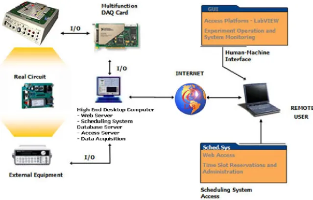
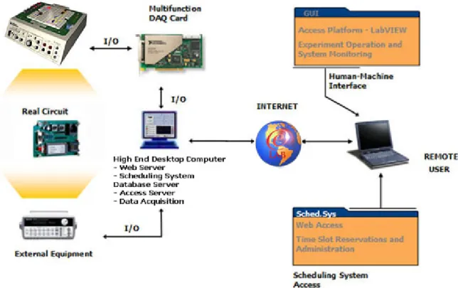
(16) Allowing real-time access to the laboratory. It is important, however, to emphasize the fact that the term "real time" throughout this document refers to the system response time. This is, the time it takes for the user to see, on screen, the e¤ects of any change made to the circuit’s inputs or to the measurement points throughout the practice.. 1.3. Methodology. This thesis proposes a general connection scheme for remote laboratories in real time, focusing on applications in Electrical Engineering education, but that is also easily applicable to di¤erent areas of research.. This scheme is aimed to allow e¤ective,. remote operation in real time of laboratory-like equipment and practices, allowing users to retain most of the properties that traditional lab work provides, but in a remote fashion and with distributed time allocation. The proposed scheme, which is called eLab, consists of …ve main elements: Remote User (Client), Scheduling System Database Server, Access Server, Web Server, and Practice Station. The User is the remote computer connecting to the laboratory, in which a graphical interface is deployed to provide the remote operation elements of the lab to the user. The Scheduling System Database Server contains a Structured Query Language (SQL) database which stores all users’ information, such as login information, time slot allocation for a certain practice, team members, etc.. The. Access Server provides the means for the laboratory to authenticate the User into the laboratory and manages proper time slot access. The Web Server provides the User with a familiar interface to access the Scheduling System Database Server securely and allocate time slots for any practice. Finally, the Practice Station represents the laboratory practice itself, which includes Data Acquisition stations and tele-operation mechanisms to allow the experiment to be accessed and manipulated remotely. Figure 1 shows the proposed connection scheme. The Practice Station in Figure 1 consists of real circuits connected, via DAQ cards, to a Data Acquisition computer. This computer, besides acquiring the proper measurements, also generates the signals required to operate the experiment remotely (recon…guration, signal generation, etc.). All information is handled by this computer and sent through the Internet to the User. The Web Server and both Scheduling System Database and Access servers may reside in a single computer since they all depend greatly on each other to operate; moreover, they may reside in the same Data Acquisition computer that is a part of 4.
(17) Figure 1: Proposed General Connection Scheme for Remote Laboratories. the Practice Station.. The Web Server acts as an intermediary between the User. and the Scheduling System Database Server.. This intermediary function consists. of authenticating a user into the system and allowing him to reserve di¤erent time slots for each set up practice in the remote laboratory. It also checks all user data and applies any restrictions to the system depending on speci…c user’s data. This server gives a familiar graphical interface for the user to manipulate his time slot reservations as well as to have a proper display of the system’s data. The Scheduling System Database Server hosts a previously created SQL server. It receives information modi…ed for each user by the Web Server and replies to information requests made by the Web and Access servers. All user information and reservations are stored in this server. The Access Server is the gatekeeper for the remote laboratory. It provides user authentication and reservation checks, as well as a secure access to all laboratory resources.. It sends out queries to the Scheduling System Database Server about. speci…c data for a certain user and, upon the information retrieved, decides if the user holds the proper credentials for him to access the laboratory at a certain time slot. It is also in charge of notifying the user when his reserved time is about to expire. 5.
(18) and, of course, to make the disconnection once the user’s reservation has ended. All four elements are connected via Internet to the User, which consists of a computer with a set of software-based solutions to provide access, distant operation capabilities, and data monitoring of the remote laboratory.. 1.4. Overview. This document presents the detailed description of the eLab remote laboratory implementation developed for this thesis. In it, the general architecture and the operational description of every element are reviewed. Chapter 2 presents the antecedents in remote laboratory work throughout the world, setting the environment in which this thesis focuses on and comparing what other implementations have done in this …eld. Chapter 3 presents the detailed listing of the architectural elements of our development, focusing on the way these are interconnected. Chapters 4 and 5 take on the detailed description of the two most important elements of the system and how they operate. Also, Chapter 6 presents a general analysis of how this remote laboratory is used when put to the test with a real group of students in a real class. Finally, concluding remarks, contributions, and possible future development is presented in Chapter 7.. 6.
(19) CHAPTER II ANTECEDENTS The coming of new Information Technologies, an exponential increase in the amount of information, and the accumulation that it requires in all courses, just like the swift changes in it and the technology itself have brought as a result the necessity for a constant and continuous professional development.[35] A tool that turns out to be extremely useful in this kind of needs are the redesigned courses meant to be taken through a computer, especially, laboratory practices. However, although these kind of systems called "Computer Based Training" (CBT) have been developed in the past 10 years to replace traditional engineering courses [7, 20, 4], they have some limitations that have stopped their total immersion in the scholar curriculum, such as programming di¢ culties, complicated structures, use and hardware limitations, and perhaps the most important reason, the cost of implementation. Thanks to the versatility and increasing availability of the Internet, especially in the educational …eld, a desire to give access to the information of all courses through the network has been arising, allowing it to be used from virtually anywhere with an Internet-connected machine. Such trend is followed by most universities, spawning programs to host online training and education.. For instance, in Tec de Monterrey, the "Educational Re-. design" has allowed their courses to add online content for the students, as well as online examinations, practices, exercises, and more. This has given teachers a new approach to the way they teach and hand out the course’s information.[13] This new approach has been documented and experimented on by Eduardo Flores in his article, "Encontrando al profesor virtual". In it, Flores conducts a 7-semesterlong experiment between traditional courses and courses with online content to support them. He found that online courses helped achieve a better student satisfaction (an increase of 20% compared to traditional courses), but also that online courses helped decrease student deserting rate by 25%.[9] Also, several fully online educational programs have been created, such as the Virtual University and PrepaNet, which are aimed not to support existing programs, but to replace them with a remote alternative.[15, 14]. 7.
(20) Even in large universities, expanding programs to reach students abroad have gained momentum in the past few years.. Some of them, like Massachusetts Insti-. tute of Technology’s OpenCourseWare or the Open University of England initiatives, are looking to make the information in their courses available, free of cost, to the world.[25, 36] Through a webpage, the theoretical information conforming their different courses are provided in popular document formats, so that the user may access them, download them, and study them at a distance.. This information includes. open textbooks, teacher-created reference materials, practice suggestions, and some student reports. Of course, such initiatives are restrictive since they provide access to all the information contained in the courses, but not to their physical resources, such as faculty members, university facilities, and practice equipment.. Figure 2: Di¤erent Online Courses. Laboratories are no exception, especially due to the di¢ culty to prepare the necessary equipment for these kind of activities for their functioning in a network; consequentially, their full development for remote access has been delayed. However, there have been e¤orts to take advantage of the use of a user-friendly graphical interface in such a versatile medium as the Web, making it possible for the students to have control of the experiment in a remote fashion. These kind of applications have been 8.
(21) denominated Virtual Laboratories. A Virtual Laboratory (VL), in the literature, has di¤erent descriptions. For the Internet2 Consortium[5], a VL is de…ned as an heterogeneously distributed environment that allows the collaboration between geographically separated groups as well as the work in a common project. For Guimares[10], a VL is a system that allows its users to plan and conduct experiments, as well as obtaining and analyzing data through teleimmersion mechanisms. In general, virtual laboratories can be classi…ed into two categories: simulated and remote.[37] In the case of simulated laboratories, these give access to both the equipment to be used as well as the environment in which they operate in a simulated way and through an Internet connection. The advantages that this laboratory scheme presents are that it allows testing and experiments in extreme or complex conditions without any damage to the equipment, besides being able to serve multiple users simultaneously, avoiding equipment damage due to inexperienced users. However, it must be pointed out, everything done in this kind of laboratories is not real, but completely simulated (often with ideal conditions). The connection scheme for this kind of laboratories is shown in Figure 3. As can be seen, this connection scheme has a simulation of the process being executed in a server machine (simulated laboratory), while the parameters to simulate or manipulate are being monitored and controlled by a client machine (student).. Figure 3: Simulated Virtual Laboratory Diagram In the case of remote laboratories, the access to physical equipment is made through a computer connected to the Internet, through DAQ systems, which have 9.
(22) access to analog and digital ports with both input and output capabilities, counters, switches, etc.. In this kind of laboratory, the user experiments with equipment in a real environment, taking data and experiment status by means of real sensors and transducers, which makes the experience the more e¤ective. However, care must be taken not to lead the experiment into extreme conditions to avoid damage to possibly expensive equipment. The connection scheme for this kind of laboratories is shown in Figure 4. In this Figure, the di¤erence between the simulated and the remote laboratories can be appreciated, since the server machine in the remote laboratory is no longer simulating the process or the circuit under experiment but accessing a real process through the teleimmersion interface (data acquisition/generation) and allowing the client machine to access the information and to control the real circuit parameters, thus giving the user the possibility to monitor and control the behavior of a real process at a distance.. Figure 4: Remote Virtual Laboratory Diagram. It is this last type of laboratory which is of interest for this thesis and is going to be developed throughout.. 2.1. Remote Laboratories Around The World. Although, in theory, a remote laboratory should give the user total access to the process, in reality this does not happen, especially due to the di¢ culty to remotely make changes to a process and the cost of the necessary equipment for this kind of 10.
(23) interaction. Instead, pre-de…ned experiments are set up online, of which the user can obtain information, but it is not very common for the user to be allowed to make changes in the structure of the experiment itself, which means that he does not have room for mistakes. This last point is crucial for the learning process while carrying out a laboratory practice, for it is when we make mistakes that we truly interiorize the result of our wrongdoings and apply previously seen concepts to realize we’ve made a mistake.[16] For instance, in the case of Electronics laboratories, a common remote laboratory only permits changes in the input signals of the circuit and its initial conditions, but it is not possible to change, at any time, the connection con…guration of the circuit, which limits the educational experience to a pre-established experiment model.[28] In Physics laboratories, where the recon…guration of a process under experiment is complicated, it would be very di¢ cult to implement remote experiments that allow the user to change the state of connections or the elements in the process under experimentation[11], and even less if the process is meant for didactic purposes. However, the advance towards tele-engineering projects, educational laboratories, and collaborative development of projects has been advancing and integrating new data acquisition technologies, digital manipulation, and software-applied measurement instrumentation.[22] An example of this type of software-applied measurement instrumentation are the so-called Virtual Instruments. Through a specialized software tool, graphical user interfaces (GUIs) that allow the control of accessories as well of data acquisition and generation can be easily created. Besides, the functionality to allow a GUI to be published as a web page immediately is available in certain software packages, giving access to the users to a remote process in real time. Some of the functions required in a remote laboratory may be to have an internal function generator (and con…gurable in real time from the GUI), variable and …xed power sources, current analyzer, multimeter, input and output ports, and digital and analog ports.[12] All this, together with control and acquisition through a card or port in the computer, allow the user to access di¤erent measurement and test points throughout the remote circuit. Massachusetts Institute of Technology’s iLab The Massachusetts Institute of Technology has developed an online laboratory program called iLabs since 1999, as a part of their iCampus project in alliance with Microsoft.[24] This program is focused to developing remote laboratories for di¤erent 11.
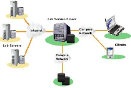
(24) subjects, such as Electronics, Physics, Robotics, etc... Their proposed connection. scheme is shown in Figure 5.. Figure 5: iLab Architecture (Source: iLab Project). This architecture proposes an intermediary between the clients and the lab servers, called Service Broker. This Broker system is set up to receive all user requests for an experiment, including experiment con…guration (such as input signals, waveforms, etc.) and redirect them to the proper lab server, as well as receive experiment information from the laboratory servers and redirect them to the proper user. This process is done in a batched way, which means that the Broker can receive several experiment requests, but only sends out one request per lab server at a time, placing all experiment request in a queue. This request is then received by the lab server who, in turn, applies the experiment conditions requested by the user and performs the experiment while saving the measurement data requested by the user. When the experiment is …nished, the results are sent back to the Service Broker, which then sends the results back to the user and submits the next experiment request in queue.. This Broker also handles user authentication and data storage for lab. servers.[28] The implementation of such architecture implies that the experimentation is never carried out in real time and that the user never has a direct manipulation of the remote laboratory. In experiments which require a set up time, such as Physics experiments like a heat exchanger or Chemical processes like a timed reaction, this condition is excellent, given the fact that multiple experiment requests may lie in the Service 12.
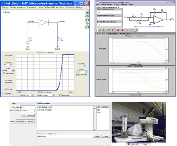
(25) Broker while the time-consuming experiment is carried out for one request (allowing for set up times between requests) and that the users don’t have to wait for the set up times to submit their experiment request. For this kind of applications, having to wait a certain period of time to get an experiment’s results is not so bad. However, for experiments with small time constants, such as Electronics Experiments, having to wait minutes to get results for an experiment that, at most, takes seconds to carry out, is not such an advantage. For such processes, a real time monitoring and manipulation of the experiment itself it’s a highly desirable condition. The graphical user interface used by iLabs is Java-based, which is adapted by each lab instructor to suit their speci…c experiment needs. A set of instructions to implement in the Java programming for the lab interface to communicate with the Service Broker is given out, too. An example of a few of their interfaces is shown in Figure 6.. Figure 6: iLab’s Interface Examples (Source: iLab Project). An advantage of these interfaces programmed in Java, is that they can be easily 13.
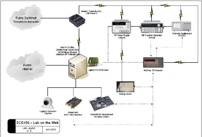
(26) deployed over the web, with the user being required only to download the Java plug-in, which is available, free of charge, from Sun Microsystems. University Of Toronto’s Lab on The Web The University of Toronto has implemented a project born of one of its Electronics Design courses, called Lab on The Web.. This remote laboratory implementation. seeks to implement remote access to standard laboratory equipment. The connection scheme proposed in their development is shown in Figure 7.. Figure 7: Lab on The Web Architecture (Source: Lab On The Web report). This architecture now gives direct laboratory access to the user. The main element in their architecture is the lab server, which hosts the Data Acquisition cards and connects to the standard lab equipment (oscilloscopes, power sources, function generators, etc.). The user connects to the lab server via Internet and, once authenticated, has a direct connection to the equipment, allowing him to perform measurements in real time and to operate standard equipment remotely. In contrast to MIT’s development, this architecture allows the user to have a real time experience with real equipment. 14. However, modi…cations to the circuit’s.
(27) con…guration is not permitted. This means that the user may only operate the lab equipment remotely, but cannot change the circuit itself or the points to which any of the lab equipment’s terminals are connected, limiting the experiment to a …xed con…guration with minimum condition change capability for the user. Also, di¤erent from iLab, Lab on the Web does not enqueue the lab requests, but gives direct, immediate access to the lab resources to the user. This, however, has limited the deployment of this architecture; since only one user can operate the laboratory at any moment, a time table for the usage of the lab has to be assigned by lab instructors. Consequentially, as of completion of this thesis, Lab on The Web has not been fully implemented into any courses.[30] The lab interfaces created for this lab are created for standard, commercial lab equipment in National Instruments’ LabVIEW. Their interfaces are divided into two: user interfaces and lab interfaces.. The server interfaces are connected to the. di¤erent equipment via a General Purpose Interface Bus (GPIB), and take on the task of generating commands to operate each equipment and acquire the data they send. The user interfaces are applications given to the user with a graphical interface to operate the lab equipment.. These user interfaces connect, via TCP/IP, to the. server interfaces. An example of these interfaces is shown in Figure 8.. Figure 8: Lab on The Web’s Interface Examples (Source: Lab on The Web report). Although LabVIEW allows for better graphical interfaces than other platforms, it is clear that Lab on The Web’s interfaces are not so well polished. In addition, 15.
(28) in order for these interfaces to work, the user is handed out a set of LabVIEW …les (VIs), which force the user to hold a valid LabVIEW license and copy installed in his computer, which are not free, unlike iLab’s Java plug-in. However, this is a limitation brought on by the way Lab on The Web deploys its interfaces, since LabVIEW also has options that do not require the user to purchase a LabVIEW license. Norwegian University of Science and Technology’s Next Generation Lab The Norwegian University of Science and Technology’s Next Generation Lab (NGL) is also aimed at providing access to traditional laboratory equipment via Internet. Their connection scheme di¤ers from the past examples, as shown in Figure 9.. Figure 9: Next Generation Lab Architecture (Source: NGL project). The architecture presented by this remote laboratory implementation takes into account two di¤erent servers: one to provide access to the user and one to provide access to the laboratory equipment. The user server hosts all user information and permissions, as well as general information about the experiment. The equipment server hosts the set of instructions to generate commands for the lab equipment and receives information sent out by them. Both servers are connected via Internet once a user requests experiment access.. This scheme, like Lab on The Web’s, allows. the user to enjoy a direct connection to the laboratory equipment. 16. However, in.
(29) this implementation, the experience is not in real time since now two servers are involved into taking and processing information, which adds a considerable delay to the process. Their entire development is based upon Microsoft’s .NET technology.[27] Just like Lab on The Web, this implementation connects traditional laboratory instruments to the equipment server. This server hosts all the necessary interfaces and instructions, in a .NET application, to send out commands and receive information from the instrumentation. Also, these instruments are connected to a CMOS chip, where all the experiment’s elements are embedded. The user then connects, through the user server, to the lab practice. He manipulates the instrument’s con…guration with simple commands in an XML webpage and also receives instrument information in the same page.. This process, however, is relayed, since the information that. both the user and the equipment generate has to pass through and be processed by two di¤erent server computers.. The experience is not in real time because the. webpage has to be constructed by the user server every time new information from the equipment server is received, adding to the overall download time. The interfaces used to operate the lab are all web based and run under .NET technology; thus, in order to have access to the lab, the user only requires a web browser with the .NET Framework installed, which is freely available from Microsoft. This provides the lab with a very noticeable advantage, since its users have minimum software requirements to operate the lab (most of which are commonly pre-installed in common PCs).. However, the use of .NET’s web technology does not allow the. creation of highly developed graphical interfaces, but rather interfaces with common web elements, such as tables, text …elds, buttons, etc... A few examples of NGL’s. interfaces are shown in Figure 10.. Figure 10: Next Generation Lab Interface Examples (Source: NGL Project). Monterrey Tech’s eLab The proposed scheme in Monterrey Tech’s implementation, called eLab, consists of …ve main elements: Remote User (Client), Scheduling System Database Server, 17.
(30) Access Server, Web Server, and Practice Station. The User is the remote computer connecting to the laboratory, in which a graphical interface is deployed to provide the remote operation elements of the lab to the user. The Scheduling System Database Server contains a Structured Query Language (SQL) database which stores all users’ information, such as login information, time slot allocation for a certain practice, team members, etc.. The Access Server provides the means for the laboratory to. authenticate the User into the laboratory and manages proper time slot access. The Web Server provides the User with a familiar interface to access the Scheduling System Database Server securely and allocate time slots for any practice. Finally, the Practice Station represents the laboratory practice itself, which includes Data Acquisition stations and tele-operation mechanisms to allow the experiment to be accessed and manipulated remotely. Figure 11 shows the proposed architecture.. Figure 11: eLab’s Architecture. In this development, a direct access to the labortory equipment is proposed. This is to seek a real-time experience for the user. Also, a Scheduling System is going to be implemented to allow the user to have the freedom of choosing his own lab schedule rather than being handed out a …xed one. This would allow enough ‡exibility for the user and would also ease the overall laboratory administration process. 18.
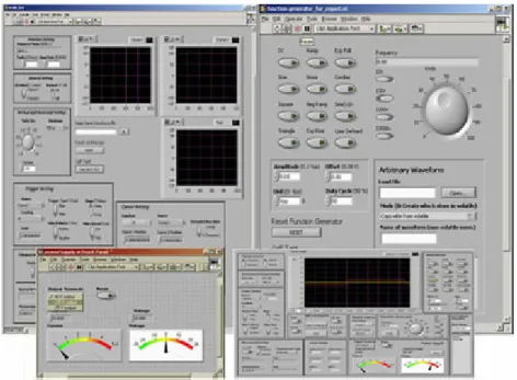
(31) Access to the laboratory equipment interfaces is proposed to be implemented through web-based LabVIEW applications by using the integrated Web Server in the development tool. By using this kind of VIs, we can allow the user to have control of the interfaces, as well as to be able to monitor the results shown in them, through a standard webpage with a LabVIEW Runtime plug-in installed.. 2.2. Laboratory Comparison. In this section, a comparison between remote laboratories is carried out.. With. all the information given in the previous section, along with this thesis’ proposed methodology detailed before, we are able to determine di¤erences and similarities among these remote lab implementations; also, key points may be found for our development to address and attack. 2.2.1. Interface Technology. The technology used for the laboratory interfaces in all implementations varies greatly. Therefore, it is a key point to decide which technology provides the best balanced set of features and justify the selection made for this thesis.. Table 1 shows this. comparison. Technology. Deployment. Free. GUI Level. iLab. Java. Web. Yes. Low/Med. Lab on The Web. LabVIEW. Application. No. High. Next Generation Lab. .NET. Web. Yes. Med. eLab. LabVIEW (Via WebServer). Web. Yes. High. Table 1: Laboratory Interface Technology Comparison It is apparent from Table 1 that the general trend in remote laboratories is to make the lab equipment available to the user with a web-based deployment, rather than giving the user a separate application to do so.[3] It is for this reason that the interface technology of choice for the present thesis was National Instruments’LabVIEW, using its integrated Web Server, which allows LabVIEW applications to run in a web-based solution.. This web-based approach. is similar to that of Java interfaces, but with a higher degree of GUI customization and, of course, LabVIEW connectivity, which allows the user to control a LabVIEW VI remotely.. This is done by loading the control panel of the VI into the user’s. 19.
(32) computer via the web interface, but not the program code itself (which still runs in the local server). Figure 12 shows a graphical comparison between them.. Figure 12: Graphical User Interface Comparison. There are also di¤erent programming languages available than the ones reviewed for these labs. Some of the most popular among the scienti…c community are C++, C#, Visual Basic, and MATLab.. The interfaces that can be created with these. programming languages are as varied as the ones seen above, mostly depending upon the level of expertise of the programmer and time spent in the development of the interfaces.. While all of these programming languages are meant to be deployed. through stand-alone applications (executable …les) or as software-speci…c program …les, some of them, like C# and Visual Basic, can be adapted to work with .NETbased webpages (.NET itself being based upon C# programming). If the deployment is done as a program …le, then the user is obligated to own a valid license for the speci…c software in order for him to run the application.. Stand-alone executables. don’t require the user to have an extra software license, but usually produce much larger …lesizes than simple program …les. Table 2 shows a brief comparison of these programming languages. Language. Deployment. GUI Level. Language Complexity. C++/C#. Stand-Alone/Web. Med/High. High. Visual Basic. Stand-Alone. Med/High. Med. MATLab. Stand-Alone. Low/Med. High. Table 2: Alternate Programming Language Comparison. 20.
(33) 2.2.1.1 Connectivity Issues Connectivity for a remote laboratory application is crucial. All of the programming languages and technologies reviewed previously are capable of interacting with laboratory equipment, Data Acquisition cards, and are also capable of connecting through the Internet in a variety of ways. These capacities, however, do not come as naturally for some of them, especially when equipment connectivity is addressed. For instance, in the case of Java, .NET, C++, and C#, network connectivity is added through a simple, pre-programmed module that needs to be added to the interface.. Equipment connectivity, on the other hand, is not as simple.. In order. for these programming languages to be able to connect and interact with traditional laboratory equipment, those communication modules have to be developed by the programmer, thus adding to the overall interface programming complexity.. If the. instrumentation is going to be emulated using Virtual Instruments, then the communication has to be with Data Acquisition equipment; such communication modules must also be developed for each language and speci…c DAQ model.[32, 31] In Visual Basic and MATLab, network connectivity modules are also simple, preprogrammed additions. For traditional lab instruments, depending on the way this equipment communicates with the computer, these communication modules could also be already included, for Visual Basic and MATLab have GPIB and Serial communication modules included in their libraries.. These modules, however, have to. be tweaked and adapted for each speci…c instrument model.. Thus, programming. complexity is not greatly a¤ected, but it is not as simple as with other programming languages. On the other hand, communication with most DAQ equipment is not as readily available and has to be, in most cases, programmed from scratch.[38, 26] With LabVIEW, these issues are completely covered with included modules. Network connectivity can be implemented with a variety of included functions or, to reduce programming complexity, can be completely left for the programming tool to implement by using the included Web Server, which, as seen before, automatically handles the network connection between the remote, published operation panel and the local application.. Communication with laboratory equipment is also usually. included, especially if the instruments are connectable through GPIB or serial interfaces; also, in most cases, the vendor of the laboratory instrumentation usually provides proprietary LabVIEW functions to interact with their equipment. This facilitates the programming and development of the graphical user interfaces since the programmer saves time programming and can spend more of it polishing the look of. 21.
(34) the interface itself. Table 3 shows a summary of the modules that each programming language requires to be developed. Connectivity Module Required Programming Language. Network. Instrument. DAQ. Java. No. Yes. Yes. C++/#. No. Yes. Yes. Visual Basic. No. Usually. Yes. MATLab. No. Usually. Yes. LabVIEW. No. No. No. Table 3: Connectivity Module Programming Comparison 2.2.2. Laboratory Equipment Cost. The cost of every remote laboratory implementation is greatly a¤ected by the kind of equipment that is going to be set up for remote access. Since the cost of individual models vary from brand to brand, only a qualitative view of the cost is considered; also, for the sake of a fair comparison, only Electronics laboratories from each implementation are taken into account. This comparison is shown in Table 4. Equipment iLab. Cost. Virtual/Traditional Low/High. Lab on The Web. Traditional. High. Next Generation Lab. Traditional. High. eLab. Virtual/Traditional Low/High. Table 4: Laboratory Equipment Comparison Although the trend in this subject seems to be to use traditional laboratory equipment for remote experimentation, the choice for this thesis was to use Virtual Instruments, which cost less to implement and provide more ‡exibility of operation, although not being as specialized and robust as commercial equipment. The reason for this choice will become clear in Chapter 3, which will also present an architecture proposal for a remote laboratory with traditional equipment as well. 2.2.3. Access Implementation. Access control and operational implementation in each remote lab architecture seen before is carried out in a variety of ways. 22. The number of servers involved in the.
(35) connection process greatly impacts not only the general cost of the implementation itself, but also the time delay introduced to the data stream. Also, the way these servers are con…gured also determine if the user is directly connected to the lab’s resources or just sends con…guration parameters and receives measurement data from a data server rather than the lab equipment itself. For instance, Lab on The Web and eLab both boast a direct connection to the laboratory equipment they provide (being traditional equipment or Virtual Instruments) by allowing the user to connect to the equipment server directly through an Internet connection, thus reducing data latency and providing a real time experience of the laboratory. However, their implementations di¤er in they way they provide their GUIs to the user. Lab on The Web provides the user with a LabVIEW program …le that acts as a client connecting to a server application running in their equipment server; as stated before, this forces the user to possess a valid LabVIEW license and software copy in his computer. eLab, on the other hand, deploys its interfaces via a webpage using the LabVIEW Runtime free plug-in. Next Generation Lab and iLab don’t provide this direct access to the equipment. Instead, they place two di¤erent servers between the user and the laboratory equipment, which adds data latency.. However, the purpose of these two servers varies. in each implementation, making data latency to have a di¤erent implication in each case. In Next Generation Lab, there exist a user server and an equipment server, but the data‡ow from and to the lab instruments goes through both servers before reaching the user. In this case, in order for the equipment server to be actively connected, a user has to be connected as well.. Therefore, data latency does have a negative. impact on the user’s experience, since it means that data generated by the laboratory equipment is relayed by two servers before reaching the user, and vice versa. In iLab, the access is meant to be batched.. This kind of access states that. experiment requests are stored into a Broker server and put into a queue before being sent to the lab servers to be executed; measurement data also follows this process, being sent to the user when his experiment request has been ful…lled and measurement data collected. Since this access, by nature, implies a delayed experiment execution, data latency induced by the two-server con…guration is negligible. between all labs is shown in Table 5.. 23. A comparison.
(36) Number of Servers. Direct Connection. Connection Type. iLab. 2. No. Batched. Lab on The Web. 1. Yes. Real Time. Next Generation Lab. 2. No. Relayed. eLab. 1. Yes. Real Time. Table 5: Access Implementation Comparison From Table 5 it can be inferred that a direct connection to the equipment is highly desirable, since it provides the user with a better experience of the lab practice. However, as it was seen before, a direct connection to real equipment means that users who want to use the remote lab have to wait until the user currently using the equipment is …nished. The choice for this work was to provide a direct connection to the equipment since a real time experience for the user was sought. Chapter 3 further elaborates on the architecture designed and chosen for eLab. 2.2.4. Experimentation Process. The way laboratory practices and experiments are carried out in remote laboratories is de…nitely not the same as in traditional ones. Even more, the way these experiments are carried out varies greatly among remote lab implementations. MIT’s iLab, with its batched structure, implies that all experiment requests are received once, with all input modi…cations, probe placement, and device selection ready. With this, their experiments are a collection of pre-established models (such as common circuits or device characterization devices). Moreover, the experiment’s conditions are fed into the proper equipment (voltage sources, function generators) and then the experiment is run. The user has the ability to change input parameters only, not to modify circuit connections, topologies, nor speci…c elements.. Also,. the level of interaction he has with the experiment itself is very limited, since the experiment is actually performed by the lab servers with the con…guration received, and not by the user himself. Next Generation Lab is a similar story. Their experiments are pre-de…ned and the user connects only to run these experiments, only being able to modify certain input signals and monitoring waveform-acquiring equipment. This remote laboratory implementation, however prede…ned, has a higher level of interactivity for the user, since now the experiment being executed is being run by the user, modifying and. 24.
(37) monitoring the experiment as it happens.. The two-server con…guration that this. lab implements, however, makes this data generation and collection process a delayed one. Lab on The Web overcomes this time limitation.. Now, the user executes the. experiment and receives data in real time. Nonetheless, their experiments are still pre-de…ned ones, allowing the user to change some input signals or de…ne some start and end points to a device characterization experiment; the user doesn’t really perform the experiment, but only provides initial conditions to the process. eLab, on the other hand, allows the user to de…ne the experiment’s process entirely, and allowing the data connection to be in real time. In the implementation achieved by this thesis work, the experiment’s process is not prede…ned, allowing the user to make changes to input signals and receive the immediate circuit’s response to those changes. Also, the whole process is not prede…ned; if the user has to perform, for instance, device characterization on a diode, the experiment is not run for him, but by him, letting the user construct the voltage-current curve point by point and as with many measurements as the user wishes. Room for mistakes is also allowed, since the whole experiment process is not prede…ned, thus granting the user the opportunity to learn from his mistakes and correcting them in real time, just as if he would in a traditional laboratory. A comparison of the experimentation processes applied in each remote laboratory is presented in Table 6. Level of Interactivity. Prede…ned Procedure. iLab. Low. Yes. Lab on The Web. High. Yes. Next Generation Lab. Med. Yes. eLab. High. No. Table 6: Experimentaton Process Comparison. 25.
(38) CHAPTER III SYSTEM ARCHITECTURE The implementation of a remote laboratory requires for it to be structured properly. Such structure, as seen in previous examples, is determined by the way the lab equipment is going to be accessed by the user, the kind of laboratory equipment itself, and the connection experience that is going to be given to the user. The area of study to which the laboratory is to be implemented is also a determining factor as to how this remote deployment is going to be carried out. For this thesis, an application in Electrical Engineering courses is taken into account for the design of the connection scheme. Given the objectives set for the present thesis, a remote laboratory model that satis…es these demands and complies with the required speci…cations was envisioned. However, before laying out an architecture for the lab connection, the main elements that would conform it need to be identi…ed and clearly de…ned. To accomplish such a task, the objectives of the thesis need to be revisited. First and foremost, a connection scheme that allows the user to remotely control and access a laboratory facility is needed. Also, such a connection has to allow the user to connect to the equipment while retaining as much of a traditional lab experience as possible, which means that a real time experience is highly desirable, as opposed to a batched experience, where the user’s experiment request has to enter a queue and the results are sent out later in time.[17] Another objective of this thesis is to prove that a remote laboratory implementation can reduce lab costs considerably, which means that low cost options need to be taken into account. The most important feature that is going to be addressed is laboratory availability and ‡exibility.. Since, theoretically, a remote laboratory may operate twentyfour. hours a day, it means that an access scheme need also be designed. Even more, if we take this characteristic and mix it with the desired real time access to the laboratory, we …nd that the access to the laboratory cannot be simultaneous for two users. It is precisely this last point which introduces a new need for remote laboratories which does not exactly exist in traditional labs: a scheduling system.[23] In traditional laboratories, for instance, in a university, practices are developed and planned for a …xed number of hours a week, and users (in this case, students) are also given. 26.
(39) …xed schedules for an entire semester. In remote laboratories, however, in order to achieve access ‡exibility and to allow the student to choose speci…c and di¤erent times for each practice, a scheduling system is required. Such a system should have a user database for authentication and a way for the user to choose and reserve certain time slots for each practice. For added ‡exibility, it can have a determined number of time slots available for the users for each practice, thus avoiding excessive reservations for a single user. This system will be connected to laboratory interface in order to determine if a certain user has access to the experiment at any given time.. 3.1. Architectural Elements. With these requirements in mind, we identify …ve basic elements to conform the proposed architecture: User (Client), Practice Station, Scheduling System Database Server, Access Server, and Web Server. 3.1.1. Remote User (Client). The Client element is one that is present in all implementations, for it is, ultimately, the element where the …nal user of the development resides.. In the case of the. work presented here, the User holds a minimum set of specialized tools in order to access the laboratory. On the Client’s side, the system will provide a gateway for the user to use the graphical interfaces designed to interact with the Practice Station described below. Also, the User will provide access to the needed Scheduling System, as discussed earlier. According to the set objectives, all of the access for the Client will be carried out via a Web-based interface; access to the practice’s GUI and Scheduling System will be carried out through a Web browser with the appropriate plug-ins installed. The general requirements in the Client’s computer are: Standard Web browser, such as Microsoft’s Internet Explorer and Netscape’s Navigator (Mozilla’s Firefox browser is not supported). National Instruments’LabVIEW Runtime plug-in (free and automatically downloaded if the browser’s security options allow it), version 7.1 or higher. Microsoft’s .NET 1.1 Framework (free and downloadable from Microsoft’s webpage).. 27.
(40) 3.1.2. Scheduling System Database Server. As stated before, the implementation of a real-time, remote laboratory implies that only one user per equipment can be using the laboratory at any given time, forcing the creation of a Scheduling System. For this task, as well as for user administration purposes, a database is the most reasonable tool of choice. For the Scheduling System Database Server, a database is envisioned to hold user information which, eventually, will also serve the Access and Web Servers listed above. The user information contained in the database will be sorted and catalogued in di¤erent tables across the database, helping in the administration of users and di¤erent laboratory data. Such information includes username and password, team information, course information, and time slot reservations. Most of the information stored in the database is given by the laboratory administrator, like general user data, but all reservation information comes from the User, by accessing the Scheduling System.. The information, generated by the User by. reserving a certain time slot at a certain date, is later used by the Access Server to determine if the user has clearance to use the laboratory at a certain time. Since access to the Scheduling System Database in the Client’s side is carried out through a Web browser with Microsoft’s .NET technology, the database tool of choice for this thesis was Microsoft’s SQL Server 2000, given its full compatibility with the web interface and with LabVIEW’s applications. The general requirements for the Scheduling System Database Server are: Microsoft’s Windows 2000 or XP operative system (Windows 2000 is recommended). Microsoft’s SQL Server 2000 or higher. Microsoft’s .NET 1.1 Framework. The Windows user has to be given access to the master database. 3.1.3. Access Server. The Access Server is key to the proper access management of the remote laboratory. It acts as a gatekeeper for all of the elements of the system the User has access to. This server is, mainly, in charge of validating a user’s login information when trying to access the laboratory’s Scheduling System or the Practice Station itself. For the Scheduling System, the Access Server is in charge of validating user login 28.
(41) information (login and password are matched to a valid, registered user); when this is checked, the Access Server provides the proper permissions for the User to access the Scheduling System Database and begin selecting the allowed number of time slot allocations. For the Practice Station, the process is divided into two steps. First, the Access Server also checks and validates the received user login information. Second, when login information is veri…ed, the Access Server then queries the Scheduling System Database for the valid reservation made for the current time and date.. The in-. formation replied by the Scheduling System is then compared with the current user information.. If the currently reserved time slot is registered to the user, then the. Access Server grants permission for the Practice Station to be accessed; if the reservation information does not match that of the user (reservation made by another user or no valid reservation found for the current time and date), then the user is showed a proper message and disconnected from the system. Since the Access Server is serving gatekeeping functions to the Scheduling System Database and the Practice Station, the connection between them is di¤erent for each case. The connection to the Scheduling System is made through a webpage based in .NET technology, while the connection to the Practice Station is made through LabVIEW functions. Therefore, the general requirements for the Access Server are: Microsoft’s .NET 1.1 Framework. National Instruments’LabVIEW 7.1 or higher. National Instruments’Enterprise Connectivity for LabVIEW. Microsoft’s VisualStudio 2000 or higher (for .NET webpage development only). 3.1.4. Web Server. The Web Server in the development proposed in this thesis acts as a hub for all other elements of the system; it provides interconnection among them.. The main. idea of the Web Server, given the fact that the laboratory is to be accessed through a web-based interface, is to provide the User with a readily available technology for this access. Webpages are ideal for this task, given the widespread use of the World Wide Web and the popularity of Hypertext Markup Language (HTML) pages.[33] This server hosts all course information, from general description of the laboratory and teacher information, to practice documents, descriptions, and instructions.. It. also hosts the access pages to the Scheduling System and to the Practice Station’s 29.
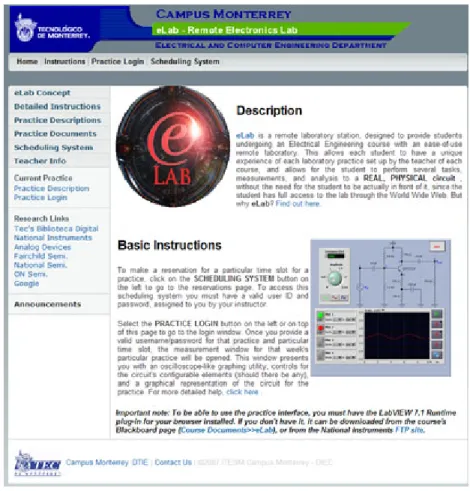
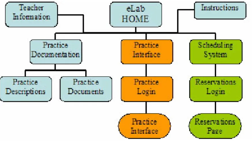
(42) interface. It is this server that the User reaches when trying to use the laboratory, and it is from this server that all other accesses are dealt with. Since access to all other elements of the system is carried out through this Web Server, the general requirements for it must comply with all other elements of the architecture; said requirements are: Microsoft’s Windows 2000 or XP operative system. Microsoft’s Internet Information System installed and activated (included with the OS). Microsoft’s .NET 1.1 Framework. Connection to the Practice Station’s LabVIEW Web Server. Connection to the Access Server’s .NET webpage for the Scheduling System. 3.1.4.1 eLab Webpage For the Web Server element, a webpage set was created to provide a centralized access point for the User to the rest of the system.. For this thesis, such page is hosted. into a single domain name, http://elab.mty.itesm.mx. Figure 13 shows an overview of eLab’s home page. The main goal of this main page is to encapsulate the entire laboratory development into a single, centralized solution. Besides, it simpli…es access to the user, since he only has to access a single web address to access all elements of the system, regardless of weather they are in the same server computer or not.. This webpage. provides access to course information, teacher information, laboratory practice documentation, and access to the two main elements of the system: Scheduling System and Practice Interface. To grant access to all these elements, all …ve elements of the architecture have to interact with each other in a web-based solution. Since both the Scheduling System and Practice Interface were implemented into a webpage of their own, it was only natural that this general webpage would harbor them.. From this main webpage, the User can select to view simple information. about the course, the laboratory itself, or its practices, or can access all the other systems. Another advantage that this main webpage development permits is the simultaneous use of the Scheduling System. Given the fact that the Remote User only accesses this webpage, from it, the Scheduling System Reservation Page can be duplicated for 30.
(43) Figure 13: eLab’s Home Page Overview. as many connected users as the Web Server allows.. Figure 14 shows the webpage. dependancy of the eLab domain. 3.1.5. Practice Station. The Practice Station is where the connection to the lab equipment resides. It includes the laboratory equipment, the computer used to access it, all computer peripherals utilized for the interface between them, data acquisition systems included in the connection, and graphical user interfaces used to control and monitor the equipment. This section of the proposed architecture for this thesis is the one that is most ‡exible, since it can be adapted to di¤erent areas of research, di¤erent experiments, and even di¤erent technologies. But, as stated before, the purpose of this thesis is to develop a remote laboratory in real time, with applications to Electronics Engineering, so experiments of this sort will be considered to design a connection scheme for our work. Also, the interface programming tool of choice is National Instruments’ LabVIEW. 31.
Figure

+7
Documento similar
Recent observations of the bulge display a gradient of the mean metallicity and of [Ƚ/Fe] with distance from galactic plane.. Bulge regions away from the plane are less
In the previous sections we have shown how astronomical alignments and solar hierophanies – with a common interest in the solstices − were substantiated in the
(hundreds of kHz). Resolution problems are directly related to the resulting accuracy of the computation, as it was seen in [18], so 32-bit floating point may not be appropriate
Results show that both HFP-based and fixed-point arithmetic achieve a simulation step around 10 ns for a full-bridge converter model.. A comparison regarding resolution and accuracy
Even though the 1920s offered new employment opportunities in industries previously closed to women, often the women who took these jobs found themselves exploited.. No matter
Furthermore, the user has access to a smartphone application, which is able to show information in real time, or statistics of radiation values computed in remote web server:
MD simulations in this and previous work has allowed us to propose a relation between the nature of the interactions at the interface and the observed properties of nanofluids:
The expansionary monetary policy measures have had a negative impact on net interest margins both via the reduction in interest rates and –less powerfully- the flattening of the
