DESIGN, NAVIGATION AND STRUCTURE OF A HYPERMEDIA APPLICATION FOR THE TEACHING-LEARNING OF PNEUMATIC ENGINEERING DESIGN DRAWING
Ramos Barbero B.; Pelaez Vara J.; García Maté E.; Ruiz Calvo J. Área de Expresión Gráfica en la Ingeniería.
Universidad de Burgos (España) Escuela Politécnica Superior.
Avda. General Vigón s/n 09006 Burgos. (España) E-mail: [email protected]
Tel: 00 34 947-258926 / 258927
ABSTRACT
This article presents a hypermedia application used to study pneumatics that serves to support the lecturer in the lecture hall and as a self-study tool for the student. The reasoning behind the creation of this application is as follows: currently, there is no application on the market, which is equipped with a navigational system to guide the student through this subject matter, which has a system for self-assessment, and a system to identify those concepts that are of greatest interest or difficulty for the student. The proposed system monitors the time each user spends studying each section, as well as the dates on which each they are studied. Moreover, students are able to monitor their progress in learning the subject matter and identify those areas in which they have to improve. They are also able to simulate any pneumatic circuit in order to check its feasibility or detect any errors. The application has an open, modular structure, which enables changes to be made without its structure being affected. Use of the hypermedia application has supported the tutorial work of lecturers and reduced time spent elaborating on subject matter in the lecture hall, at the same time as facilitating its study.
Keywords: Multimedia, hypermedia, architecture for educational purposes,
technological systems, interactive learning environments, computer-aided instruction, pneumatic engineering, educational engineering materials.
1. INTRODUCTION
Technical drawing for industrial purposes, according to [1, is a means of written communication used by technicians to lay out and convey the information needed for the design, construction, operation and verification of every type of material used in industry. Technical drawing is able to represent mechanical, electric and electronic installations as well as each of their respective components.
Pneumatic systems are found within mechanical systems and they are widely used in productive processes for the manufacture, transport and handling of products.
programme that simulates pneumatic circuits and FluidSim-3-Pneumatics [3, which in addition to simulation contains explanations that refer to its animated components, examples of their applications and didactic videos. These help the student to learn more about pneumatic components, as well as how to establish the necessary connections to achieve a desired sequence of operations. However, the navigational structure is based on drop-down menus, lacks any system for the students to evaluate their own progress in learning the subject matter and lacks a system that assists in the identification of those areas of the subject matter in which the student is experiencing most difficulty.
The reasons described above have led to the design of the pneumatic engineering design drawing hypermedia. Our aims have been to facilitate navigation, guide students through their studies, synthesize the course contents, avoid excessive time spent tracing out complex drawings on the blackboard, avoid improvisations by the teacher and present the subject matter through pictures, videos and animations. These aspects, in conjunction with explanatory texts, form part of the interconnected information that will improve the learning of pneumatics.
2. PHASES IN THE DEVELOPMENT OF THE PNEUMATIC ENGINEERING
DESIGN DRAWING HYPERMEDIA
The planning of a multimedia-based course does not notably differ from a conventional course, for which reason it is necessary to undertake each of the phases referred to in [4 and 5 that are set out below:
Identify the subject matter of the course
Identify the group of students who are to be taught on the course Set out the teaching objectives
Lay out the broad structure of the hypermedia application Set out the course structure
Set out the structure of the chapters
Propose activities and develop a self-assessment system for the subject matter Design the interface
However, a multimedia course demands more meticulous planning and structuring than a conventional course, due to the fact that the hypermedia course must not only contain the information that has to be conveyed to the student, but should also provide orientation throughout the course, a task that the teacher normally fulfils.
2.1.IDENTIFICATION OF THE SUBJECT MATTER OF THE COURSE
Pneumatics is defined as a technique that uses compressed air, as a means of transmitting energy in automated processes [6.
Pneumatics is widely used in industry, which is why knowledge related to its design as well as its maintenance is of great interest to the industrial engineer. In both cases, some basic knowledge of how its components function is necessary, as well as knowledge of the tasks they perform and the methodology used to determine the control mechanisms.
The graphical symbols used to represent all of the constituents that are present in a pneumatic circuit are standardised by CETOP (European Oil Hydraulic and Pneumatic Committee) and ISO (International Organisation for Standardisation). This representation is drawn up in accordance with the functional operation of each constituent, for which reason the student must be familiar with the functions of each component in order to understand the significance of their graphical representation and to be able to interpret or design pneumatic circuits.
2.2.IDENTIFICATION OF THE GROUP OF STUDENTS TO BE TAUGHT ON
THE COURSE.
A course is designed to increase the knowledge of students of one level or another, which is why any pre-existing knowledge held by the student must be assessed in order to define the starting point for the course [4,5.
Any knowledge held by students is of vital importance, since the characteristics of the group form the basis on which the objectives of the course are drawn up. If the basis of the subject matter is misconceived, the result will not be entirely satisfactory, and even more so on a hypermedia-based course, in which there is no room for manoeuvre. Since its contents are developed beforehand, they cannot be immediately changed, as they can on a conventional course, as that would call for the hypermedia to be redesigned.
Despite the students having different needs and/or attributes, which have some influence over the design and effectiveness of the hypermedia application, they also have shared aims such as obtaining information in as short a time as possible, with minimum effort, and purged of all information that does not directly concern the subject matter [7.
Evaluation of any prior knowledge was assessed through a pre-course test that corresponded to the objectives of the subject matter. The results showed that of 151 students enrolled on the course, only 22 possessed some knowledge of pneumatics. This suggests that the hypermedia should contain the basic concepts of the subject matter. It should provide a system which allows the student to advance step by step using interactive functions so as to introduce the subject to those students with no prior knowledge of pneumatics, and to allow students with some knowledge of the subject to interact with the system. It should also contain activities at higher levels to ensure that the most advanced students also have to opportunity to progress.
2.3.DESCRIPTION OF THE DIDACTIC OBJECTIVES
Detailed descriptions of objectives targeted on the course are necessary in order to select and structure the course material. These will be decided upon in relation to the needs of the student and the objectives set out for the qualification for which they are studying.
The final objective of the “pneumatic engineering design drawing” hypermedia is to enable the student to design and maintain pneumatic systems. Before this goal may be achieved, the student must meet the following objectives:
Full knowledge of the symbols that represent the constituent parts of a pneumatic system.
Understand the operation of pneumatic parts solely referring to the corresponding symbols.
Understand and design pneumatic circuits.
2.4.GENERAL STRUCTURE OF THE APPLICATION
In order for it to assist the student in a self-study programme of the subject matter, identify those parts of the subject matter that present greatest difficulty and facilitate the addition or revision of the materials in use, the proposed hypermedia should meet the following conditions:
Its structure must be open to be able to introduce new materials or modify existing ones.
Its structure will be modular, so that the changes to one module will not affect the others and so that new modules may be generated without affecting the general structure [8.
It must be able to simulate the circuits referred to in the course material.
It must be equipped with a system of self-assessment that allows students to reflect on the degree to which they have mastered a subject and the areas that require further attention.
It should have a system that allows the lecturer to identify those areas in which students experience greatest difficulty.
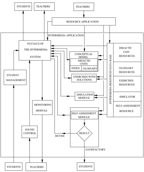
Figure 1. General structure of the hypermedia application
The structure can be divided up into modules that fulfil the following functions:
- Student management module: this module creates the list of application users and assigns a password to each user.
- Nucleus of the hypermedia system: the control centre responsible for directing different data flows, images and files, using the authoring programme Macromedia Authorware.
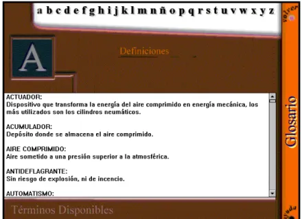
- Conceptual module: this manages the contents of each didactic unit, through the creation of hypermedia documents. It also contains a glossary that allows the student to become familiar with terms and their definitions set out in alphabetical order. - Exercise module: this module displays various exercises and simulations of the
proposed tasks and corresponding pneumatic circuits.
- Design and simulation module: using a commercial simulator [2 it is possible to go over exercises on the operation of circuits in the previous module or any other proposed circuit.
- Self-assessment module: the aim of this module is to ensure that the student is aware of the level of knowledge acquired, as well as on those concepts that require further attention to gain deeper understanding of the subject matter.
- Monitoring module: this module enables the lecturer to monitor the student's progress, throughout the course, in relation to study dates, the number of times the
student accesses each section of the materials and the time spent on each one. With this tool, the lecturer facilitates/provides tutorials on those sections in which the student is experiencing the greatest difficulty. It also allows the weak points of the application to be isolated.
In the hypermedia, students have access to didactic units, to the module on solutions, the simulation module and the self-assessment module.
The lecturer is able to use the hypermedia as a support medium in the lecture hall, is able to control the sound of the application and is able to access the monitoring module, to check up on those concepts studied by the student and the time spent on each one. In addition, the lecturer can gain access through the resource management module, to the hypermedia resource database, in order to modify or introduce new material; and to the central nucleus of the system to modify or create new nodes or navigational links.
2.5.COURSE STRUCTURE
The hypermedia application opens with a student management screen, from which the user is granted access to the tool after having introduced a password, a name and a surname. This information is used to create a user database, and to open a series of files, where data is stored for the purposes of student follow up.
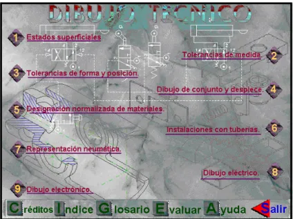
When the application is accessed, the screen in figure 2 displays two chapters into which the subject of technical drawing is divided. Clicking on one of the chapters takes us to the chapter contents page. At this point, the only available chapter is number 7 on the subject of pneumatic representation.
2.6.STRUCTURE OF THE CHAPTERS OR CONCEPTUAL MODULE
The chapters have been structured in the same way as a textbook in which the contents page lists the chapters, lessons and sections into which the material is divided. It is also possible to consult an alphabetical index that lists the pages on which particular concepts may be studied [11,12,13. The choice of this type of navigation is justified by the need for sequential navigation, for students who do not possess prior knowledge of pneumatic engineering; but which also assists those students who possess some knowledge of the subject matter, as made clear under section 2.2.
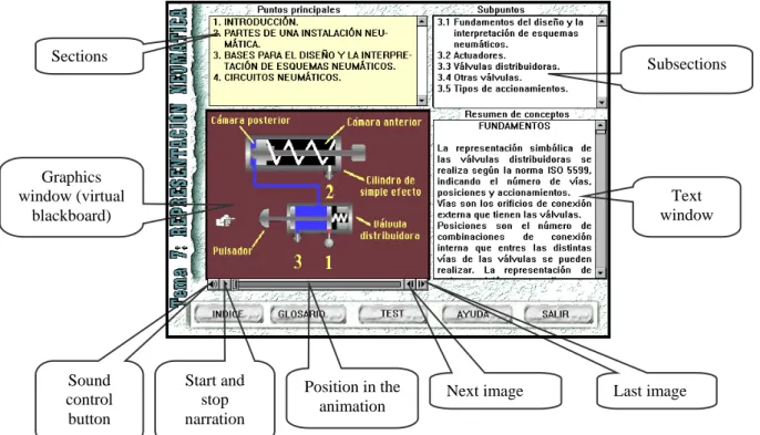
In this way, having selected the chapter on pneumatic representations on the screen shown in figure 2, the screen in figure 3 is then displayed. The upper left-hand part of the screen displays the lessons that make up the chapter. Clicking the selected lesson makes its different sections appear on the upper right-hand side of the screen. Clicking on one of the lesson sections displays a collection of images or animations and their corresponding texts on the lower left-hand of the screen. At the same time, on the lower right-hand side of the screen, a text window appears which displays a summary of the concepts being studied.
Figure 3. Main Screen - Pneumatic devices
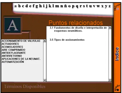
The same result is obtained by clicking the index button shown in figure 3. In this case, the screen shown in figure 4 is accessed, which displays the letters of the alphabet. Selecting the first letter of the concept to be defined displays the terms that start with that letter on the left-hand side of the screen. The sections that refer to that particular concept appear on the right-hand side of the screen, when the term in question is selected. Selecting the section moves us to the screen shown in figure 3, with the text and animations that correspond to the desired term.
Subsections
Text window Sections
Graphics window (virtual
blackboard)
Sound control button
Start and stop narration
Position in the
Figure 4. Index
2.7.STRUCTURE OF THE EXERCISE SOLUTIONS MODULE
The exercises have been elaborated in accordance with the previously stated didactic objectives and they are intended to comply with the first five levels of the taxonomy as proposed by Bloom [4,7.
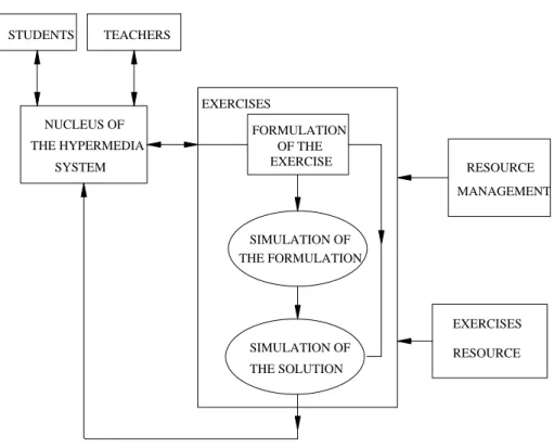
The exercise solutions module, which is external to the conceptual module, but is linked to the nucleus or hypermedia manager, displays the available exercises on the first screen. Selecting any of them accesses the screen in figure 5 that is divided into three sections: the formulation at the top of the screen, graphic representation and animation of the formulation on the lower left-hand side of the screen, and the solution to the exercise on the lower right-hand side.
Figure 5. Exercise Screen
Formulation
Step-by-step solution
Activating the icon "Ver animación (Watch Animation)" opens an external *.avi file that displays the animation relating to the formulation. Activating the icon "Ver Solución (See Solution)" opens an external *.mov file that displays the solution to the exercise. It should be noted that the animated resources are held on files that are external to the exercise user file, and that this module may only be accessed through the nucleus of the hypermedia application, as shown in figure 6.
Figure 6. Structure of the exercise module
The student can complete the exercises manually and subsequently see the proposed solution, or complete the exercise using the pneumatic simulator and then check that it works correctly.
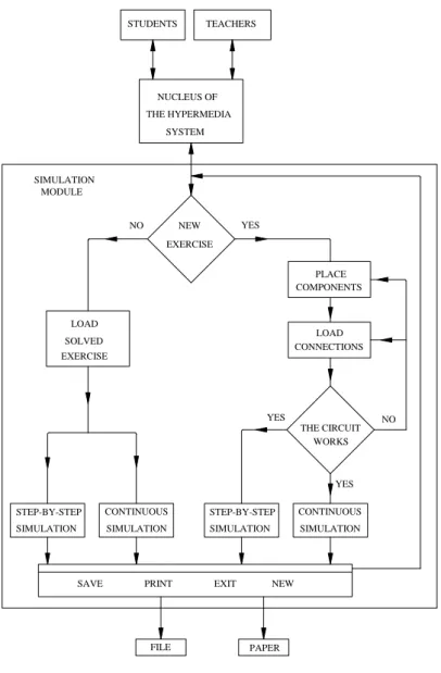
2.8.STRUCTURE OF THE SIMULATION MODULE
This module is accessed from the nucleus of the hypermedia application, as shown in figure 7. Using the “JumOutReturn” function, the external simulation programme Pneusim can be executed, which offers two possibilities:
NUCLEUS OF
SYSTEM THE HYPERMEDIA
STUDENTS TEACHERS
EXERCISES
RESOURCE FORMULATION
OF THE EXERCISE
SIMULATION OF THE FORMULATION
THE SOLUTION EXERCISES
MANAGEMENT RESOURCE
Figure 7. Structure of the simulation module
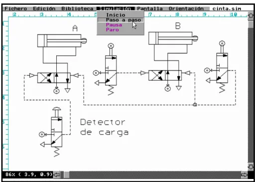
- Open an exercise that has previously been completed and saved as an external *.sim resource. After loading the exercise, the simulation is displayed on screen in two different ways: step by step or continuously.
Figure 8. Pneusim pneumatic circuit simulator
2.9.STRUCTURE OF THE SELF-ASSESSMENT MODULE
The self-assessment file is external to the file that is accessed from the “test” button on the screen shown in figure 3. The user can select any of the proposed questionnaires. Each questionnaire has twelve questions and each one of them has four possible answers. Only one answer per question is allowed, which can always be modified before activating the “terminar (quit)” button shown in figure 9. After closing the questionnaire, the module displays the number of correct answers and if any mistakes were made, it also displays a series of recommendations and appropriate sections to study in greater depth.
2.10. STRUCTURE OF THE MONITORING MODULE
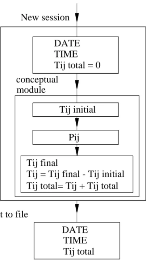
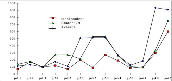
This module monitors the number of times that a student enters the hypermedia application, as well as the dates and the time spent on it [14. In each session, the time Tij total spent on each section Pij is calculated, as shown in figure 10. Each time Pij is opened, the time Tij is added to the time already spent on that session and on that specific section.
Figure 10. Structure of the self-assessment module.
When the hypermedia session is closed, the times and dates are saved to a file that can be consulted at any time.
In figure 11, the graph shows the time spent by one particular student, the average length of time for all of the students in the class and the time spent by an ideal student. The basis of the calculations for the ideal student was the average time spent studying the subject by four university professors, who were unfamiliar with the subject matter. By comparing the time of the ideal student with the average for all students, those parts of the subject matter in which students experience greatest difficulty may be identified. Furthermore, by comparing the average length of time spent by all students with the time spent by any one particular student, the variations in the time spent by each pupil in relation to all of the other students in the class may also be identified.
Tij initial New session
Pij
Tij final DATE TIME Tij total = 0
module
Tij = Tij final - Tij initial Tij total= Tij + Tij total
DATE
Tij total TIME Print to file
Figure 11. Graph of student study hours.
2.11. STRUCTURE OF THE STUDENT MANAGEMENT MODULE
This module creates a list of users in the hypermedia application in the data file data.txt. The process by which the module is executed is shown in figure 12.
Figure 12. Structure of the student management module
2.12. SCREEN DESIGN
A series of points [4,5 should be considered when designing the screen. The screen has to display the necessary information, should make the subject matter appear attractive, and facilitate interaction between the student and the application, etc.
When the course material is compiled, it is often the case that on each screen everything revolves around a main message. In order to structure the different screens, a good technique is to formulate the main messages, add the text, sound and illustrations that go with them and subsequently link them together [5,15.
The screen display is basically composed of two parts:
The message
The situation and navigational tools
The message, which should be located at the centre of the screen is made up of illustrations and text. The illustrations are the first to capture the attention and be observed and remembered, which is why they should obviously be representative of the message.
The text constitutes the explanation of the message. To facilitate on-screen reading the font size should be larger than that used on paper. The texts must be brief and concise [7, since a text that appears on paper to be short, takes up much more space on screen, which is due not only to the font size, but also to the fact that the lines are much shorter than the full width of the screen.
The tools that the student needs to progress and navigate are found at the edge of the screen. The buttons that are found on every page should always be found at the same place [4,5. The interactive mediums should be uniform so that the student can quickly learn their functional aspects.
All of the screens allow access to the lessons and their respective sections, so that the student is able to move easily from one to another and has an idea of the breadth of the subject matter.
The navigational buttons should be situated towards the bottom of the screen, as the text ends there and it is necessary at that point to move on to another screen.
The main screen, shown in figure 3, has been designed bearing in mind the above-mentioned considerations.
Figure 13. Glossary Screen
3. CONCLUSIONS
The use of the hypermedia as a medium to support lecturing and as a self-study tool for the student has led to the following conclusions.
1. The time spent by students on each section of the subject matter reveals the importance attributed by students to the concepts explained in each section, or an inadequate presentation of the concepts being dealt with.
2. The dates on which the student studied shows that greater effort is invested over the time leading up to an evaluation, with only a low percentage of students studying the subject matter on an on-going basis.
3. The modular nature of the hypermedia system has allowed a commercial simulator to be integrated into the application.
4. The simulation of circuits assists the tutorial work of the lecturer, which is very important bearing in mind ever-increasing student numbers at university and the implantation in Europe of ECTS (European Credit Transfer System).
5. The simulation of exercises allows different solutions to the same problem to be compared.
6. The proposed open system allows for easy modification of any part of the application.
BIBLIOGRAPHY
[1. Ramos Barbero, B.; García Maté, E. Dibujo Técnico. Madrid. AENOR 1999
[2. Leclair, D.; Leclair, R.; Rainville, F.; Mylchreest, P. Pneusim. Lichfield Staffordshire. Nogren Martonair 1992
[3. Festo. FluidSim 3 Neumática. Festo
[4. Buchwald Andersen, P. A Practical Guide to Multimedia.Denmark. PLS Consult 1994
[5. Peláez Vara, J.; Alvarez de Ron González, V.; Pascua Frades, J. “Multimedia technology applied to the learning of multimedia tools”. Journal of Computer Applications in Technology. Vol 14 No 1/2/3. 2001
[6. Peláez Vara, J.; García Maté, E. Neumática Industrial: Diseño, selección y estudio de elementos neumáticos. Madrid. Cie inversiones editoriales Dossat 2000 SL. 2002. [7. Jim Carter. “ A framework for the development of multimedia systems for use in engineering education”. Computer & education 39. 2002.
[8 Christian, C.A.; Eisenhamer, B.; Eisenhamer, J.; Teays, T. “Amazing Space: Educational Resources from Current Scientific Research Results from the Hubble Space Telescope”. Journal of Science Education and Technology, Vol. 10 No 1, 2001
[9. Eguiluz, J.I.; Sánchez, P.; Cavia, M.A.¸Lavandero, J.C.; Martínez, J.L.; “ Adaptación de las pruebas objetivas en ingeniería eléctrica, para el aprendizaje / evaluación, siguiendo la evolución de las tecnologías de la información”. VI Congreso universitario de innovación educativa en las enseñanzas técnicas. La Palma de Gran Canaria 1998.
[10. Velasco, M.C.; Arciniega, R.; Cózar, J.Mª.; Hernández, M.A.; Rafales, J.C.; Turégano, J.A. “La termodinámica técnica como aplicación del sistema multimedia gestor / autor”. I Jornadas nacionales de ingeniería termodinámica. Badajoz 1999
[11 Bustos Martín, I. Guía práctica para usuarios de multimedia. Madrid. Anaya 1996 [12 Nick, S. Andresen, J. Lübkerand, B. and Thuman, L. “CHEMnet – structure, design, and evaluation of an online chemistry course”. Journal of Science Education and Technology, Vol 12 No 3. 2003.
[13 Marx, R.W. Blumenfeld, P.C. Krajcik, J.H. and Soloway E. “New Technologies for teacher professional development”. Teaching and Teacher Education, Vol 14 No 1. 1998
[14 Tucker, E. “The impact of CAL in a university engineering school”. Education + training, Vol 39 No 7. 1997