FIELD TESTS WITH AN AERIAL-GROUND
CONVOY SYSTEM FOR COLLABORATIVE TASKS
J. VALENTE, A. BARRIENTOS, A. MARTINEZ, C. FIEDERLING
Robotics and Cybernetics Group, Centro de Automática y Robótica UPM-CSIC; [email protected]
This chapter presents the design, implementation and field experiments of a convoy between an aerial and a terrestrial robot. The convoy strategy proposed is indeed very simple and based in a PD control law. We intro-duce the robots Pinky and Gaia, robots which have been part of the FRACTAL fleet, the general system set up is also addressed, such as the ground station workloads and the middleware architecture. Finally, com-prehensive experimental results shown herein, demonstrate the good per-formance and usability of the system in multi-robot behavioral research.
1
Introduction
A Multi-robot system (MRS) has many advantages over a Single-robot system (SRS), robot systems with robots endowed with different abilities and different degrees of autonomy play an important role in coordination and cooperation tasks. The usability of a MRS can range from military to civil applications, such as, De-mining (MacArthur, 2005), Agriculture (Elfes, 1999), Forestry, Urban Search and Rescue (Blumenthal, 2008), In-spection and monitoring (Chaimowicz, 2004).
The set up of a physical robot fleet is not an easy task, when working with those platforms, dozens hours in outdoor environments are needed until you achieve the minimum desired results, moreover this often means handling difficult climate conditions, like strong winds, cold, rain and even snow, preventing the rapid research development. This chapter present our effort to set up a convoy of terrestrial and ground robots, and is organized as follow: Section 2, reviews some of the researches comprising the usage of ground and aerial robots, Section 3, gives an overall description the sys-tem, namely the platforms employed, the software architecture and the base station workloads, Section 4, described the methods implemented and the experimental set up, Section 5, report the results achieved, and Section 6 present the conclusions and research directions of our system.
2
Related work
A ground and aerial robot arrangement have been used oftentimes in re-search, due to an augmented range of applications. Many fruitful results have been presented so far, however we will just briefly review some of them.
3
System overview
In this section we will give an overview of the platforms used in those ex-periments, the system software architecture and the main components that made up the ground station.
3.1 Robot
platforms
The platforms depicted in Fig. 1 belong to the FRACTAL fleet and have been acquired commercially with the purpose to be applied in cooperative and collaborative tasks. With them we have developed architectures, algorithms and hardware components, specifically designed to address the problems of cooperation, coordination, command and control, in different scenarios. In Fig. 1 are depicted the aerial and ground robots.
Aerial robot
The aerial robot called Gaia is a mini vertical takeoff and landing helicop-ter denoted by quad-rotor.
Gaia provides a 3-axis gyroscopes, 3-axis accelerometers, 3-axis mag-netometer, GPS, and in addition a barometer. Moreover, has also a servo mounted in the main frame, which enables a commercial zoom digital camera to be tilted up to 100 degrees. This instrumentation assures the platform stabilization, manual control, and way-point navigation, as well to dispatch the commands from a software mission planner set in the ground station, which enables the operation of the robot to a higher level.
Ground robot
Fig. 1. From the left to the right, the ground robot Pinky and the aerial robot Gaia respectively
3.2 Ground station
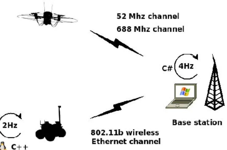
The main components of the ground station are the communications work-load and the Graphical User Interface (GUI). The ground station computer receives and sends data to Gaia through a RS-232 down-link and up-link, which communicates with the quad-rotor through a Radio Control (RC) system that has available 9 channels and operates at 35 MHz. Additionally, a video transmission downlink link at 688 MHz, is also set to receive video images acquired through the digital camera.
As part of the conditioning of an aerial robot system, is to develop a Graphical User Interface (GUI) that provides the operator with basic in-formation about the flight and mission status. Since it is more operator than user oriented, we denote it as Graphical Operator Interface (GOI).
The interface display all navigation data, vehicle status, video image from the on-board camera, providing also, in-flight image and video re-cording and storing, and general data logging, likewise a TCP/IP client connection enables the real time in-flight data transmission to a server.
The main feature of this interface is the embedded real time web map-ping API therein. Some examples of web mapmap-ping software are Open Lay-ers, Google earth, Open Street Map, Marble, etc.
The goal of this design is to improve the operator vigilance level by sti-mulating his/her situational awareness, the main idea is not only to feed-back the operator with the robot sensory information but also provide an approximate real map of the robot environment. Although we have not made Human-Robot interaction (HRI) experiments with this interface de-sign we believe that this approach improves de-significantly the operator res-ponsiveness.
This feature also plays an important role in the tele-operation of mini aerial robots over large environments, where the operator field-of-view is affected by the robot distance.
In tele-operation mode an operator can steer the quad-rotor through a RC command or through a joystick. With the RC command, odd from steering the platform, the operator can tilt the digital camera servo, take image shots and zoom the camera.
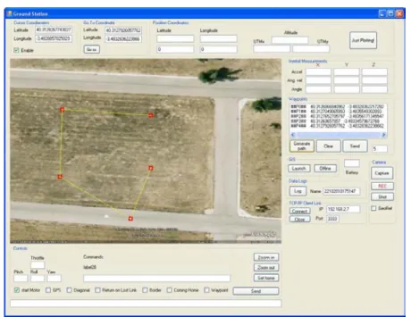
Moreover, is also possible to define a way-point route by directly click in the embedded web mapping panel, as shown in Fig. 3. When steering the quad-rotor with the joystick, if the operator needs to have a larger im-age from the digital camera, it can switch view between the web mapping panel and the video image panel (i.e. by pressing a joystick button), like-wise the opposite (see Fig. 4).
Fig. 3. The GOI in the stand-by modality where is depicted a prior planned way-point trajectory
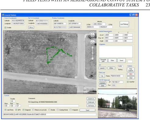
Fig. 5. The GOI in the off-line modality, this is without internet connection
Finally, this design is focused in outdoor applications, being difficult, to extended it applicability to indoor environments since the robot position is mapped through the GPS coordinates.
3.3 Fractal architecture
The first step to the development of a MRS is the design of a reliable ar-chitecture to handle the perception, localization, guidance, navigation and control modules, namely is from vital importance the low-level communi-cation that ensures an efficient data exchange between each individual ro-bot and/or the team and the ground station.
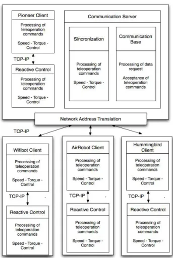
The overall software architecture developed can be seen in Fig. 6. In this particular case, the software for the FRACTAL fleet was developed to meet the following main requirements:
Multi-platform
o Must be able to handle the work-flow of several robots in real time
Robots Control
o This task is the lowest level and provides the link between sensors and actuators of each robot.
Communication link
o It is responsible for receiving orders of the base station and communicate the status of the robot and the entire fleet. Reactive Control
o This instance enables the reaction to unpredictable events, such as, unexpected obstacles or failures in communica-tion. These autonomous functions are the main security of fleet.
The communication server is the central module of the fleet, its main task is to send commands and read the robots status, as also to promote the collection, and sharing of those variables through the connected peers. For security reasons, this server is designed to work inside the robot leader be-cause it increases the service availability to the subordinate robots in case of connection failure with the base station. Furthermore, the software can also be executed from any computer within the network, enabling the use of the fleet without a leader.
The communication system uses the "Network Address Translation" (NAT) function, which is a IP packets address modification process. In the FRACTAL network, the NAT function is used to generate a subnet FRACTAL BASE. The leader is equipped with two wireless networks devices to generate a subnet to connect the slave robots. The last NAT type transformation occurs in the slave robots, where it can connect its on-board system, like a camera or other Ethernet device to a wireless network.
identifi-cation of the robot and the service requested, in order to aid the addition of new robots slaves to the system leader.
Besides the above, the software architecture promote a distributed sys-tem design, including the following configurations:
1. Server, client, reactive control and command station on the same processor.
2. Server and base station running in a processor and client and reac-tive control in another.
3. Server, leader client, leader reactive control and distributed reac-tive control running in a processor, slave client running in another, and the command station in a third one.
4
The convoy strategy
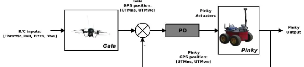
The proposed approach works by using a simple PD control law which en-able the ground robot to follow the trajectory of the aerial robot based in their global position raw data.
The discrete control law applied can be written as,
) ) 1 ( ) ( ( ) ( ) (
ek ek e k k
u , (1)
where , α, β, stand for bias reference value, proportional gain, diffe-rential gain and time. Additionally, eis an error term, which is the differ-ence between the set point and the process variable. An abstract schematic of the control employed is shown in Fig. 7.
Fig. 7. An abstract control scheme from the strategy employed
5
Experiments and results
The experiments were conducted at the CSIC installations, on the north-west of Madrid, Spain, with geographic coordinates 40º18'47.43'' N and 3º29'01.02'' W.
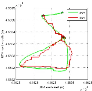
Although the aerial robot has the capability to perform autonomous way-point navigation, for a matter of safety, it was not possible to perform an autonomous trajectory based in way-points, mainly due to strong winds during the day. For that motive the quad-rotor was tele-operated during this experiment. In Fig. 8 is shown the 2D trajectory and in Fig. 9 the 3D trajectory (i.e. the height of the Gaia is also depicted), were is clear the path traversed simultaneously by the robots.
Fig. 8. Convoy 2D trajectory
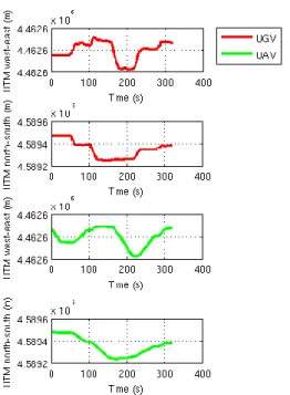
Fig. 10 shows the robots positions versus time, where we can see that both positions plots, from the UGV and UAV have similar patterns, the following lasted five minutes, and the data samples were sent to the Pinky
Fig. 9. Results from the Aerial and Ground robots positions in 3D during the experiments
The graph shown in Fig. 11 shows an average error of 2.13 meters in the UTM North-South coordinates, and an average error of 2.52 meters in the UTM West-East coordinates. This error is perfectly normal and is due the own nature of the global position system. Moreover, the data packages haven't been processed, instead we are using directly the raw coordinates through the UGV following control.
Fig. 11. Position errors
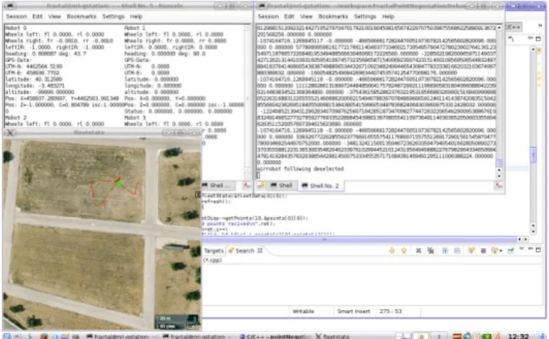
In Fig. 13 are shown a sequence of video samples from the experiment and a wind speed measurement of the same day, although the screenshot have little resolution the video from the experiment will be available at the research group home page1. Another screenshot was taken in the same day
from the Pinky operator computer where is also depicted both robot paths (see Fig. 12).
Fig. 12. Snapshot from the ground robot operator computer after the completion of the experiment
Fig. 13. Pinky (red square) following the Gaia (green square)
6
Conclusions and Future work
In this chapter we have shown some experiments with a convoy made up by an heterogeneous team of robots, one aerial and another terrestrial, ro-bots which have contribute to the development of the FRACTAL project. We have also made a brief introduction to the FRACTAL software archi-tecture, focusing in their structure and usability. A simple convoy scheme between Gaia and Pinky was arranged with the purpose to prove the relia-bility of the framework proposed and to study the development of a beha-vior where an aerial robot and ground robot could collaborate/coordinate among them. The results achieved in the experiments demonstrate that the architecture has a good performance in multi-robot coordination tasks, and that using just raw data from a GPS can be inefficient for certain tasks de-mands.
glob-al reference frame. Our strategy will consist in the implementation of a dif-ferential GPS, and in the development of an embedding visual system.
Acknowledgements
This work was supported by the Robotics and Cybernetics Group at Tech-nique University of Madrid (Spain), and funded under the project FRACTAL: Fleet of cooperative terrestrial and aerial robots, sponsored by the Spain Ministry of Education and Science (DPI 2006-03444), by the ROBOCITY 2030 project, sponsored by the Community of Madrid (S-0505/DPI/ 000235). The authors would like also to thanks to Angela Ri-beiro for the availability during the experiments.
References
Blumenthal, S., Holz, D., Linder, T., Molitor, P., Surmann, H., and Tre-tyakov, V. 2008. Teleoperated visual inspection and surveillance with un-manned ground and aerial vehicles. In Remote Engineering and Virtual In-strumentation.
Chaimowicz, L., Grocholsky, B., Keller, J. F., Kumar, V., and Taylor, C. J. 2004. Experiments in multirobot air-ground coordination. In in Proc. of the 2004 International Conference on Robotics and Automation, pp. 4053-4058.
Elfes, A., Bergerman, M., Carvalho, J., de Paiva, E., Ramos, J., and Bu-eno, S. 1999. Air-ground robotic ensembles for cooperative applications: Concepts and preliminary results. In 2nd International Conference on Field and service Robotics, Pittsburgh, Pa (USA), pp. 75-80.
MacArthur, E. Z., MacArthur, D. and Crane, C. 2005. Use of cooperative unmanned air and ground vehicles for detection and disposal of mines. SPIE.