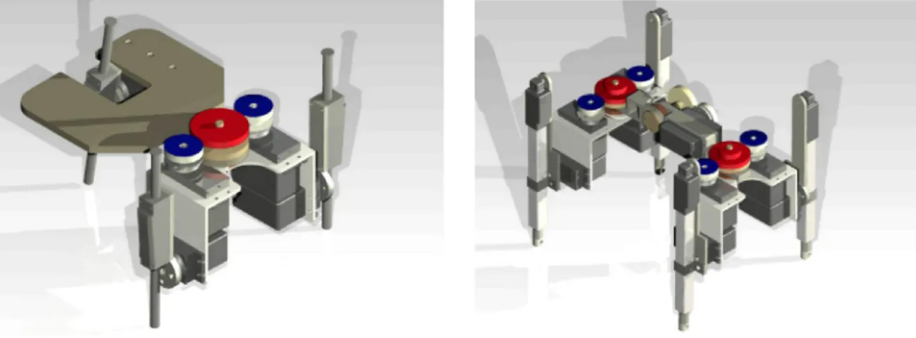
(a) 3-leg walking robot (RobotSL). (b) 4-leg walking robot (Robot4L). Fig. 1. G\D representation of the robotic modules.
Fig. 2. Example of cooperative behavior.
are developed in detail. This work is organized as follows. Section 2
presents the inverse and direct kinematic model of the leg.
The direct kinematic model is found via the Successive Screw
Displacement Method. Then the workspace of the leg is found
and finally instantaneous kinematics is introduced. In Section 3
the high level control architecture and the multi-task model are
presented. In Section 4 the communication architecture and the
user interface are developed and the experimental results are
shown in Section 5. Finally conclusions and future works are
presented.
2. Kinematic model of the leg
One of the most relevant topics of a walking robot is the design
of its legs. It must be focused not only on their individual behavior
but also on the overall behavior of the robot, considering the
desired task and posture that the robot has to achieve.
The new SMART robotic walking agents propose a four-legged
mechanism, with 3 D.o.F. for each leg composed of two rotational
joints (named hip and knee), and a prismatic joint for extending
the leg, named ext (see Fig. 3).
2.1. Direct kinematics
The direct kinematics model of the leg is obtained by applying
a successive screw displacement method [10]. This method is
based on the identification of the screw axes parameters ($), the
reference position (?„) and the target position (Pef).
Let us consider as the reference position of the mechanism the
one presented in Fig. 3. Let us attach a fixed frame Oxyz placed on
{HIP} qi
{1}
{}Jom
Link
Axis Screw
Fig. 3. Leg forward kinematics.
Table 1
Screw axis parameters.
Joint Si Si Soi di
1 2 3
( 0 , 0 , 1 ) ( 1 , 0 , 0 ) ( 0 , 0 , - 1 )
91
0
(0, 0, 0)
( 0 , - / , , - / 2 ) ( / 0 - F / 3 , - / , , O )
0 0
<(3
the hip joint, and place one screw axis in each joint with the same
direction of the joint axis. Then, the targeted position can be found
according to (1).
Pef=AiA2A3Po,
(1)
q l = 0+a
(a) Backward-Knee.
ql=0-a
0
Fx
/
•'x
\ : . / C
.' / Knee
F) /
(b) Forward-Knee. Fig. 4. Possible configurations.
2.2. Inverse kinematics
Given the nature of the kinematic chain of the leg, two possi-ble configurations may result from the inverse kinematic propossi-blem. These two possible configurations named: forward-knee and back-ward knee, depend on the selection of the state of gi.
Let us consider an arbitrary position of the foot given by f = [Fx, Fy, F^], and let us take a closer look at the projection of the leg over the XY plane, as shown in Fig. 4, where P is the projection of F over the plane XY.
As it can be seen.
U/IP dip
a = arctan(d/ip, doA) 9 = arctan(fy,fz),
(2)
(3) (4)
where dop = JF/ + Fy^, and doA = 'o +
h-Thus, the state of gi for a backward-knee or forward-knee configuration is given by (5)
(5)
qi = 9 -\- a, Knee front qi = 9 — (X, Knee back.
However, there still exists a blind gap where the selection of configuration is uncertain.
With gi known, the position of the knee joint can be found according to (6).
B = [cosgidoc, singidoc, -(2], (6)
where doc = ^/ik + hY + h'^.
The distance from the knee joint to the foot, defines the state of g3, as expressed below
93 IBf I
U
(7)where BF = OF - OB.
The state of g2 is defined as follows.
92
BFz arccos •
IBfJI
BFz g2 = — arccos
where z
Backward-Knee,
Forward-Knee,
(8)
l|Bf|| [0, 0, - 1 ] .
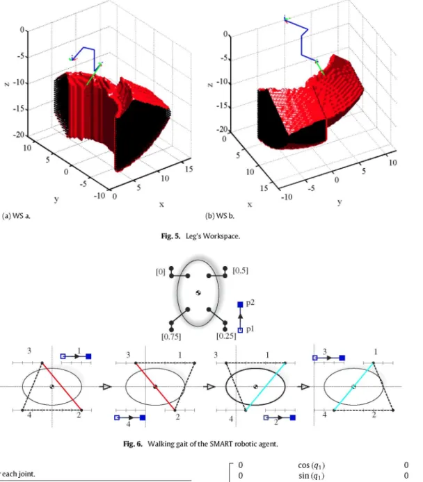
2.3. Workspace of the leg
The workspace of the kinematic chain is made up of all those possible positions where the foot can reach without exceeding the physical capabilities of the mechanism.
Therefore, several positions for the foot (f = [F^, Fy, F^, ]) are proposed, and using the inverse kinematic model of the kinematic chain, it is verified if the state of the joints resides in their work range. If the proposed position passes the verification procedure, then the position belongs to the workspace of the kinematic chain, otherwise, it is discarded.
After the evaluation of several positions taken from a rectangu-lar box of 1 cm X 1 cm X 1 cm, and considering the real amplitude of work of each joint (see Table 2), the workspace of the kinematic chain is generated and presented in Fig. 5.
2.4. Instantaneous kinematics
In order to make a synchronized movement of the leg along a desired path with a prescribed speed, the motion of the individual joint has to be carefully coordinated. This coordination is achieved by relating the joint velocity space and the foot velocity space (end effector velocity space).
According to [10], the first-order instantaneous kinematics of a serial robot can be written as (9)
X^QiJi, (9)
where $„ = [&>„, voV is the resultant twist that describes the infinitesimal displacement of the end effector, $j is the unit twist associated to the ith joint and g; is the intensity of the ith twist.
Expressing (9) in a matrix form, and defining J = [$i, $ 2 , . . . , $„], the instantaneous kinematic equation can be written as.
(10)
Therefore, the columns of } (from the Jacobian matrix of the kinematic chain), corresponds to the twists associated to each joint.
Considering that the general expressions of an unit twist for a revolute joint and a prismatic joint is given by (11) and (12) respectively.
Sn X S (11)
(12)
(a) WS a. (b) WS b.
Fig. 5. Leg's Workspace.
Fig. 6. Walking gait of tlie SMART robotic agent.
Table 2
Amplitude of work for eacli joint.
Joint Min Max Unit
qi - j r / 3 j r / 3 rad
<(2 - j r / 3 j r / 3 rad
Q3 0 100 mm
Jo
0 0 1
cos(qi) sin(qi)
0
0 0 0 0
0 0
h sin(qi) -h cos(qi)
- sin(qi) sin(q2) cos(qi) sin(q2)
- cos (92)
(13)
However, VQ is the linear velocity of a point po in the end effector that is instantaneously coincident with the origin of a reference frame in which the twists are expressed [10]. Therefore, the velocity at any point °p/ = [px, Py, Pz] will be given according to the following expressions, (15).
Wf 0)f = 0)f
v/ Vo + 'a>r
X V
(14)Taking into consideration (14), the Jacobian matrix can be rear-ranged, and expressed as.
Jf
cos(qi) sin(qi)
0 sin(qi)(-pz-|-/2)
(Pz -'2)cos(qi) Py cos(qi)-|-Px sin(qi)-|-/i
And the instantaneous kinematic equations can be rewritten as r 0
0 1
Py -Px 0
-sin(qi)sin(q2) cos(qi)sin(q2)
- cos (q2)
(15)
COf
--Jf (16)
2.5. Walking pattern for each leg
Fig. 6 shows the robot's movements while performing a walking cycle. Additionally, the initial position of the robot agent and the movement of each leg can be observed. The transfer phase is represented by the initial point • and the final point (D). Both points are linked by a straight line and the direction of the movement is shown by the arrow.
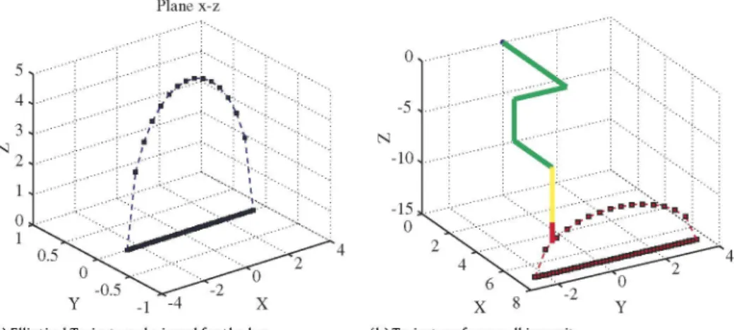
Fig. 7. Elliptical movement of robot's foot.
continuously and at the second-order to be at least differentiable. The smooth movement of the foot implies that the movement of the robot's trunk is also smooth. To ensure the smooth foot traj ectory it is required to observe spatial and temporal restrictions imposed on the kickstand. Some criteria to select the path are listed below.
• The orientation of the curve has to be normal to the ground during the upward or downward movement of the supporting foot.
• The second derivative of the curve should be continuous.
The walking mode is solved by fixing the paths that make the robot's feet; i.e. using the same path for all legs and setting an identical relative gap. In the Smart system it is proposed the legs will follow an elliptical path. This path fulfills both restrictions imposed on the motion curve. Fig. 7 shows this trajectory where the marked b point is limited by the maximum and minimum length of the third actuator.
In order to complete the leg's movement, it is necessary that the leg comes back to the initial position after the relative gap. Since the leg is in contact with the ground, it is assumed that the path described by the leg is a straight line, which should join the starting and ending points (pj„j and Pe„d) of the gap (see Fig. 8).
3. Description of the multi-task architecture
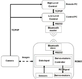
Fig. 9 shows the control scheme implemented in the SMART project. The task planning and control are centralized in a PC that acts as the master and sends out commands in order to control the modules simultaneously. Closing the control loop, a commercial IP camera is placed at the top of the scene where the robots move. This camera sends images (in bmp format) to the controlling software in the master computer.
The free library OpenCV (special functions for matrix processes and position recognition) for image processing was used. However, a especial software was developed for the orientation of the robot. With this visual information the control software can recognize each module, its position and orientation and, also, the obstacles present in the scenario. After that, it is possible to plan the path for each robot. Path calculation is based on computer vision techniques. The images that the system receives from the colored camera are the input to the computer vision system. Using a binary matrix, created in the computer vision part using OpenCV libraries, the system can search for the shortest path between two coordinates.
The matrix gives a binary view of the image. All obstacles are set to 1 and all other coordinates are set to 0. Objects and other SMART robots should be avoided. When all objects and robots are detected, the objects are expanded, in order to build a safe zone. The path planner only uses the free spaces to find a path. When moving a single robot, the other SMART robots can be seen as obstacles too. When calling the path planner function, a vector with the coordinates to move the robot to a certain position is returned. Finding all obstacles and robots in a System is not only important but they should also be identified. Fig. 10 shows a processed imaged after being taken by the camera. The trajectory generated by the path planner in order to avoid obstacles can be observed here. Based on the information given by the path planning function, the controlling block will send the commands to the robots so they can move in the correct direction. The commands can be forward, turn left or right movements. These basic movements for the robots are in text-files. Going to another coordinate can be a movement containing multiple basic movements.
3.1. Communication structure
The communication part is created in C++ and a UML scheme is shown in Fig. 11. The Socket class includes all functionality to use sockets in a client and server mode. The socket can be bound to the address of the server using the connect() function. Sending and receiving data can be done by using the read() and write() system calls.
The typical server does not initiate the connection. Instead, it waits for a client to call and request for services. The server can be established by using the listen() and accept() functions.
The Camera class uses the functionality of this socket to send, order the web cam and receive information from the socket. The communication block in the engine also uses the server side functionality of the Socket class to listen for incoming commands from the graphical user interface.
Plane x-z
0
-5
-10
6 X 8
High Level Control Move/Stop I TCP/IP Low Level Control Control PC TCP/IP Bluetooth master Images Blustairih slave RS232 Data Input
S e r v o - m o t o r s Controller
R C Signal
S«nsors S e r v o - m o t o r s
Fig. 9. Hardware and software architecture.
Fig. 10. Hardware and software architecture.
fsodoEt &A
OatM
=i Relds
T / hSocket
^ wsaData =1 Methods
V -Socket V Accept V OoseSocket V Connect V Listen V Recv * Send « S o c k e t ( + l o v e r l . . V J
Gam -*nl Cta»
=1 Re ds =1 Re
portCom ^ Methods
V '^Com V BvteToRead V OoseCom V Com(-i-loverio9-V rmt V OpenCom V WriteCom V WrtePololu
/
ComWindows ( ^ Cbu
o Relds
,1* g_cto
^ g_dcb -^ g_liCOM 1= Me
V :hods 1= Me
V "COrttWirtdOwS V BvteToRead V CloseCOM V ComWindows V InitCOM V Op enCOM V ReadCOM V WriteCOM V J
Fig. 11. UML diagram for the communication architecture.
Bluetooth communication is established in the Com and ComWindows classes. These classes contain the C++ functionality in order to bind a Bluetooth device to a certain COM port. Data can then be sent to the Bluetooth device using the WriteCom() function.
The SMART control software, called the engine, is a C++ programmed Win32 console program. It contains all the parts needed to control the SMART robots. The most important parts of
PetriNet I Planner Stop -• Control I *—• Communication Vision
I Position
Fig. 12. Scheme of the ENGINE architecture.
Table 3
OEMSPA 312i technical data.
Power class Processor Supply voltage Power consumption External dimensions Environmental conditions
l , + 7 d B m ( 5 0 m ) BGB203 Philips chipset 3-6 Vdc
1 mA (min), 17 mA (avg), 70 mA (max) 23 X 36 X 5 mm
Max operating T: - 3 0 to + 8 5 °C
the engine could be the communication net, the computer vision, the path planner and the control. The engine has a multi-threaded architecture. This makes a good amount of task-level parallelism (TLP) available. After modeling tasks by Petri Net [7] they can be implemented and executed thought a multi-threaded architecture. This advantage of a multi-threaded program allows it to operate faster. The engine architecture is given in Fig. 12. The interaction between the main parts in the engine is based on the control of threads and call function. The interaction between the main parts included in the control software can be seen here. In a modular robotic system, agents should be able to communicate through messages. More complex modular robot structures are made of a high amount of individual units. A robust communication protocol is crucial. The communication architecture has to take into account possible mechanical or electronic failures of a module.
Bluetooth communication. The SMART environment uses Bluetooth with GFSK modulation to communicate among SMART robot and control software. By using Bluetooth-based communication the SMART robot developers are able to separate the communication from the mechanical connectors. Wireless communication is suit-able for self-reconfiguring modular robots. Socket communication is used between the client user interface and the control software (kernel) and they receive images from the IP webcam. The PC run-ning the engine is equipped with a Belkin Bluetooth USB adapter. The Belkin F8T009 Bluetooth adapter supports Bluetooth version 1.2. SMART robots are equipped with the OEMSPA 3121 adapter by ConnectBlue. Once it is connected to its host system and config-ured, the Serial Port Adapter can communicate, using Bluetooth, with a wider range of other Bluetooth devices such as other Serial Port Adapters, mobile phones, handheld computers and laptops. The OEM Serial Port Adapter Electrical & Mechanical Datasheet contains important information about the OEM Serial Port Adapter. A list of the characteristics of the adapter is given in Table 3.
For the communication with the serial port adapter, the baud rate is changed to 9600 since the Pololu mini servo controller used for controlling the SMART robot servos, works at 2400 or 9600 baud. This can be done, using the OEMSPA 3121 Serial Port Adapter in the AT mode.
Thread synchronization. The ability in executing more than one process at a time is known as multi-processing. A thread is another mechanism for splitting the workload into separate execution streams. A thread is lighter in weight than a process. The engine in the SMART environment manages the different threads used in the environment. Synchronization of threads is considered, so that they do not break while executing on resources and memory.
tliread) and a communication tliread. Tlie processing tliread
in-cludes tlie computer vision part. It gets an image from tlie
web-cam, using a socl<et and does tlie processing using OpenCV. Tlie
tliread runs in a never-ending loop. In order to reach
synchroniza-tion, mutual exclusion is used. The communication thread acts as
a socket server and can receive commands from a user interface.
While receiving a command in the communication thread, some
other threads can be started such as the controlling block. The
con-trolling block can call the path planning function to update path
calculation. The program creates a new thread every time a new
action is sent by the user interface. When the previous action for
a specific robot is not yet finished, the thread is killed and a new
thread is started. The previous command will never be finished.
3.2. Socket communication
The communication that occurs between the client and the
server must be reliable. That is, no data can be dropped and have
to arrive on the side of the client in the same order as sent by
the server. TCP provides a reliable, point-to-point communication
channel for those client-server applications on the Internet.
The structure designed for the SMART environment, supports
command communication from client to server using a socket on
TCP protocol. The commands have a defined structure including
the action identifier, some parameters and a character indicate the
end of a command. The protocol designed for this communication
can be extended when new commands are included in the system.
The action identifier is a single number that is unique for each
service the server fulfills. The command associated with a given
identifier can take some parameters divided by a comma. While
the protocol is a sequence of seven bytes, the % sign is used for
dividing different commands [8].
The first byte is the command identifier. Different Petri Net
tasks can have different command identifiers. The ID of the SMART
robot is given in the second byte, followed by a comma to
separate the data. Bytes four and six are the parameters for the
command i.e. when the command is for a certain robot to move
to a point, the parameters will be an X and Y coordinate. Socket
communication is also used for receiving images from the webcam
as an input for the computer vision delivered by the controlling
software. The webcam acts as a server, sending images over the
socket to the kernel reacting on HTTP GET/POST requests from the
controlling software. The images are saved as bitmap images with
the maximum resolution.
3.3. Petri net in SMART system
The behavior modeling for both the individual agent and
the group are implemented with Petri Nets (PN). SMART is a
heterogeneous system since the robots, the IP-camera, the image
processing software and the control software are considered as
agents of the system. As a consequence.
Definition. In the SMART System, an agent is a collection of
soft-ware and hardsoft-ware elements that are able to cooperate in order to
reach a common objective.
The classical Petri net allows modeling of states, events,
condi-tions, synchronization, parallelism, choice, and iteration. For this
reason, the PN is widely used in multi-agents modeling [11-13,
5]. Even though, the agents might be treated as software systems,
the modeling concept can be taken to robot agents [14,15]. On the
other hand, the formal theory of PN allows evaluating the systems
behavioral properties, which is a way for its application to be much
more generalized.
In a strict sense, a PN is defined as an n-tuple N = [P, T, F, W},
where P is a set of states, T is a set of finite transitions. Both sets
satisfy P |^ T = 0 and P | J T 7^ 0. The weight of the arch/j,,, that
bounds the place pj with the transition t^ is defined as u; G W —>
Na+ where Na+ = {1, 2,....} is the set of positive integers. A
mark M over an N net, is a mapping P —> Na. M(pj) defines the
number of marks at Pi G P. A marked PN, is defined as NM = {N,M}
and the initial mark is noted as M°.
A place p is called an input place of a transition t if there exists
a directed arc from p to t. Place p is called an output place of
transition t if there exists a directed arc from t to p. We use •t to
denote the set of input places for a transition t. The notations t»,
•p and p» have similar meanings, e.g., p» is the set of transitions
sharing p as an input place.
Most workflow systems support a separate model of the
workflow process from the modeling of the structure of the
organization and the resources within the organization [16]. The
reasons for decoupling these two dimensions when specifying a
workflow are: the complexity is reduced, the reuse is stimulated,
and a process without changing the organizational model (and
vice-versa) can be modified. In the process dimension, the tasks
needed to be executed and the order is specified. Modeling a
workflow process definition in terms of a Petri net is rather
straightforward: tasks are modeled by transitions, conditions are
modeled by places, and cases are modeled by tokens.
Definition WF-PN. A Petri net Pw = (P,T,F) is a WF-net
(WorkFIow net) if and only if:
• Pjv has two special places: an input place, pj„, and an output
place Pout- Place pj„ is a source place: •pj„ = 0. Place Pout is a
sink place: Pout» =
0-• If a transition t* to PN is added which connects place Pout with
Pin (i.e. •t* = {Pout} and t*» = {Pi„}), then the resulting Petri
net is strongly connected.
As it was referred before, WF-PN are implemented as a
multi-threaded architecture in C++, and the synchronism is managed by
the kernel. The reader is referred to [ 17] for details. In Section 4, the
authors present two examples of behavior that show the manner
of modeling using workflow Petri Nets.
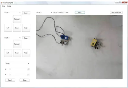
3.4. User interface
In order to improve system control and viewing, a user interface
was developed. This interface is a graphical program that allows
the user to send commands to the robots and it gives a view of the
system environment.
The commands given in the user interface are sent to the engine
which takes control over the robots. Communication between
user interface and engine is based on socket communication.
Using sockets, it is possible to create the user interface in any
programming language that support socket communication like
Java, C++ or C#. For programming the client, a C# Windows
application is chosen.
U l lidc Oft
5 ^ 3 ~ 1 OtaM 1
P
Hf>¥t
9m*
X: P m
r-- i» m
1 r s i n
Fig. 13. View of the user interface developer in C#.
tlie patli planner available in tlie engine. Anotlier functionality offered by tlie client is 'free ride'. Tliis option allows tlie user to send basic m o v e m e n t c o m m a n d s to tlie robot. Tliese actions send tlie correct c o m m a n d to tlie controlling software using a socl<et c o m m u n i c a t i o n and client communication protocol as discussed in tlie following section.
4. Experimental result
In this section t w o complete examples about modeling behavior of SMART'S agents are developed. One of t h e objectives of this project is to move a set of SMART robots in a coordinated w a y to complete a predefined task. SMART agents move inside a metallic structure t h a t has a colored IP-Camera placed 2 m e t e r s on its top. The camera takes t h e actual pictures in t h e host c o m p u t e r w h e r e the engine software runs and carries out recognition and proper decisions based on t h e c o m p u t e r vision results. This architecture is s h o w n in Fig. 14.
The time to process an image, taken by the camera, and to give a control order to a SMART robotic agent takes 150 ms. Moreover the robot has to complete t h e work, such as receiving c o m m a n d s , and moving t h e servos at t h e s a m e time. If not, a buffer will be filled w i t h unfinished c o m m a n d s .
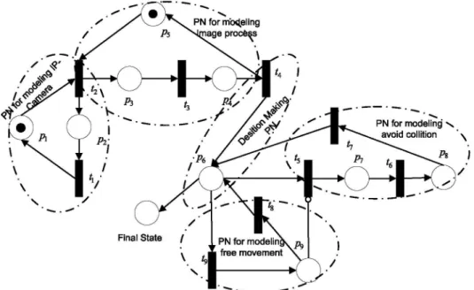
4.1. Example 1: Cooperation among SMART agents for helping a robotic agent in avoiding an obstacle
The tasks t h a t every agent of t h e SMART system realize is modeled w i t h a WF-PN. As a consequence, a m o r e complex n e t t h a t models t h e system in its totality w o u l d exist. As an example, a WF-PN w h e r e an agent m u s t change its trajectory since t h e detection of an obstacle is schematized in Fig. 15. It can be seen t h a t it is composed of 5 sub-WF-PN, detailed above.
• NJ^-'^ models the software of the image w h i c h is captured. • NJ^-^ models the image processing software, in order to get the
localization of the agents and obstacles. The capture and image processing is done 11 times per second.
• N ^ models the m o v e m e n t of any robotic agent. W h e n this sub-net is active, it implies that one or m o r e agents are moving following a free path reference.
• N^^"' models t h e avoiding collision algorithm. If t w o agents are too close, t h e y are ordered to stop and r e p r o g r a m their trajectories.
models the kernel of the application. jwCTRL
Fig. 14. Testbed for Smart project.
The sub-net t h a t models t h e camera N',^-^ is integrated by t h e followings e l e m e n t s :
Pi IP camera takes a b m p image P2 Waiting t i m e for taking a n e w image Ti Send b m p image to processing block T2 Take a n e w picture
W weighing of the arc: W G R'^"^ = {1,1} M(0) initial marking M ( 0 ) = {0}.
The sub-net t h a t model the image processing N™-^, is composed by the e l e m e n t s detailed bellow:
P3 Get an image from a kernel message
P4 Send Information of the scene to the kernel program P5 Ready to process a n e w image
T3 Processing image package
PN for mb<J.eling nage process
Fig. 15. Petri Net to model a cooperative task among SMART Agents. A robotic agent is helped to avoid an obstacle.
••^•1
^
A,
i
Fig. 16. Example 1: Cooperative Task among SMART Agents.The elements that integrates the sub-net that models the control software, N™^ are:
Pe Start the decision process
T4 XOR-Split transition. Information of robot and obstacle localization is in the control block
W weighing of the arc: W G R^"^ = {1,1} M (0) initial marking M (0) = {0}.
Fig. 17. Example 2: Cooperative Task among SMART Agents.
Transitions Ti a n d T3 m a k e t h e synchronization of t h e visual process, t h a t m e a n s if t h e process function does n o t finish its j o b , t h e IP c a m e r a is not going t o take a n e w p h o t o g r a p h .
The s u b - n e t t h a t m o d e l s t h e c o m m u n i c a t i o n interface N ^ is c o m p o s e d of,
Tg Resource Fire Transition: Send an order t o a robot b y Bluetooth
Pg Execute t h e m o v e m e n t order
Sub- R d P ^ ? modela el proc. O^
la imagen
Final State
P9
\
\ Ps • .'^
• ^ Sub- RdP del ^• ^ e n t e n qua* ' acude en ayuda
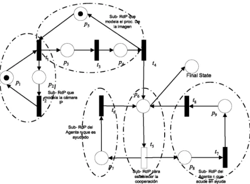
Fig. 18. Model of Cooperative task between two SMART robotic agents using Petri Nets.
W
M(0)
weighing of the arc: W G R^"^
initial marking M(0) = {0}.
{1,1}
Finally, the path planning (A*,NJ^'~°') that is integrated as a
routine in the kernel software is modeled with the following
elements,
P-j Start the Planning function
Pg Place for math consistency
Ts Resource Fire Transition. Send message to calculate a new
position
Te Calculus of the n e w position
Ty Send new position to the control block
W weighing of the arc: W G R^"^ = {1,1}
M (0) initial marking M (0) = {0}.
The above example is shown in Fig. 16. The robot agent has to
move to a new point, it can detect obstacles by using vision and
can consequently dodge them. The SMART robot detects the black
obstacle and moves around it.
agents. In the hardware agents there are two kinds of robots with
three and four legs. In any multi-agent system, its success depends
largely on its communications architecture. Therefore this article
broadly describes the model and protocol used in this system. The
software developed to control the system includes all
functional-ity that was planned for the SMART robots in this first phase of the
project. The software can easily be expanded in the future w h e n
new tasks will be added to the modular robotic system. The
de-veloped software has a typical modular robotics architecture. The
multi-agent system guarantees good performance of cooperation
tasks among agents robots, camera, userinterface and the
commu-nication protocol.
In the future an auto-connected architecture will be developed,
that is using reciprocal communication, and robots will thereby be
able to help each other. W h e n a single robot cannot finish the task,
other robots can help accomplish the task without the controlling
software having to interact. In the same manner, process calculus
will be added on board, so each module can take decisions by
itself.
4.2. Example 2: Cooperation among SMART agents to help robotic
agents to complete a task
Another task for a SMART robot, can be changing the
config-uration of robots and other objects. Fig. 17 shows a possible
sit-uation, where the yellow SMART with three legs has to move to a
new point, but there are obstacles that prevent it from carrying out
such a task. In this case, a 4-legged robot helps the yellow robot by
moving the obstacles and consequently finding a path to its final
point. This is another example of cooperation between the robots
in a modular robotic system.
This cooperative behavior is modeled by the WorkFlow Petri
Net shown in Fig. 18. In this model two new sub-nets appear to
shape the cooperation between both robotic agents.
5. Conclusions
This article presents a modular robotic system called SMART.
This system consists of different types of software and hardware
References
[1] A. Collinot, A. Drogoul, P. Benhamou, Agent oriented design of a soccer robot team, in: Proceeding of International Conference on Multi Agents Systems, 1996.
[2] S. Deloach, E. Matson, Y. Li, Applying agent oriented software engineering to cooperative robotics, in: Proceedings of the Fifteenth International Florida Artificial Intelligence Research Society Conference, 2002.
[3] H. Fiorino, C. Tessier, Agent cooperation: a petri net based model, Proceeding of International Conference on Multi Agent Systems 3 (1998).
[4] D. Franklin, T. Gresser, Is it an agent, or just a program? a taxonomy for autonomous agents, in: Proceedings of the Third International Workshop on Agent Theories, Architectures, and Languages, Springer-Verlag, 1996. [5] H. Lund, R.L. Larsen, O.s.E. Hallundbik, Distributed Control in
Self-reconfigurable Robots, Springer, 2003.
[6] L Zhiwu, X. Shuwen, On Modeling a soccer robot system using Petri nets, in: Proceeding of the IEEE International Conference on Automation Science and Engineering, Shanghai, China.
[7] J.-S. Lee, A Petri net design of command filters for semiautonomous mobile sensor networks, IEEE Transactions on Industrial Electronics 55 (2008). [8] M. Sims, D. Corkill, R.V. Lesse, Automated organization design for multi-agent
systems, pp. 151-185.
[10] L Tsai, Robot Analysis: The Mechanics of Serial and Parallel Manipulators, Wiley-lnterscience, 1999.
[11] K. Hiraishi, An elementary model for design and analysis of multi-agent systems, proc. on coordination models and languages, in: Proceedings of the 5th International Conference on Coordination Models and Languages, 2002, pp. 220-235.
[12] K. Hiraishi, Performance evaluation of workflows using continuous petri nets with interval firing speeds, lElCE Transactions on Fundamentals of Electronics, Communications and Computer Sciences 11 (2008) 3219-3228.
[13] Y.T. Kotb, S.S. Beauchemin, J.L. Barron, Petri net-based cooperation in multi-agent systems, in: Proc. of Fourth Canadian Conference on Computer and Robot Vision, 2007, CRV07, pp. 123-130.
[14] D. Corkill, S.E. Lander, Modelling, analysis and execution of multi-robot tasks using petri nets agent organizations. Object Magazine 8 (4) (2008) 41-47. [15] L Montano, J.F. Garcia, J.L. Villarroel, Using the time petri net formalism for
specification, validation, and code generation in robot-control applications. The International Journal of Robotics Research 19 (1) (2000) 59-76. [16] W. van der Aalst, Three good reasons for using a petri-net-based workflow
management system, in: [16] pp. 179-201.