Building the executive system of
autonomous aerial robots using the
Aerostack open-source framework
Martin Molina
1, Abraham Carrera
1, Alberto Camporredondo
1,
Hriday Bavle
2, Alejandro Rodriguez-Ramos
2and Pascual Campoy
2Abstract
A variety of open-source software tools are currently available to help building autonomous mobile robots. These tools have proven their effectiveness in developing different types of robotic systems, but there are still needs related to safety and efficiency that are not sufficiently covered. This article describes recent advances in the Aerostack software framework to address part of these needs, which may become critical in the case of aerial robots. The article describes a software tool that helps to develop the executive system, an important component of the control architecture whose characteristics significantly affect the quality of the final autonomous robotic system. The presented tool uses an original solution for execution control that aims at simplifying mission specification and protecting against errors, considering also the efficiency needs of aerial robots. The effectiveness of the tool was evaluated by building an experimental autonomous robot. The results of the evaluation show that it provides significant benefits about usability and reliability with acceptable development effort and computational cost. The tool is based on Robot Operating System and it is publicly available as part of the last release of the Aerostack software framework (version 3.0).
Keywords
Executive system, aerial robotics, control architecture, open-source framework, software engineering with Robot Oper-ating System (ROS), Robotics Software Design and Engineering (IJARS-ROSENG)
Date received: 26 March 2019; accepted: 11 March 2020
Topic: Robotics Software Design and Engineering Topic Editor: David Portugal
Associate Editor: Francisco Rico
Introduction
According to Kortenkamp et al.,1theexecutiveis the system of a robot control architecture responsible for translating high-level mission plans into low-level behaviors, invoking behaviors at the appropriate times, monitoring execution, and handling exceptions. The executive is a component of autonomous robots that is especially critical since its char-acteristics may affect significantly the quality of the final robotic system in aspects such as reliability and efficiency.
To facilitate the construction of the executive system, developers can use software tools that are freely available.
1Department of Artificial Intelligence, Universidad Polit´ecnica de Madrid, Madrid, Spain
2Centre for Automation and Robotics (UPM-CSIC), Universidad Polit´ecnica de Madrid, Madrid, Spain
Corresponding author:
Martin Molina, Department of Artificial Intelligence, Universidad Polit ´ecnica de Madrid, Campus de Montegancedo S/N, Boadilla del Monte, 28660 Madrid, Spain.
Email: [email protected]
International Journal of Advanced Robotic Systems
May-June 2020: 1–20
ªThe Author(s) 2020 Article reuse guidelines: sagepub.com/journals-permissions DOI: 10.1177/1729881420925000 journals.sagepub.com/home/arx
These tools are different, for example, in the way they represent mission plans. For instance, there are tools that formulate mission plans using representations based on finite state machines such as SMACH,2rFSM,3RAFCON,4 and FlexBE.5Some tools use behavior trees such as the ROS behavior_tree package6 and BehaviorTree.CPP (MOOD2Be Project). Other solutions use declarative or functional symbolic representations that facilitate the use of automated planners. For example, ROSPlan7uses PDDL and CRAM8uses Lisp and Prolog.
These tools effectively help to build autonomous robots, although there are still difficulties that have not been suffi-ciently addressed and may affect efficiency and reliability. The execution of a mission should be robust enough to handle factors such as the presence of unexpected events in the environment, user specification errors in the mission plan, and interruptions due to preemptive interaction between the user and robot. This is particularly significant in aerial robots, which normally require reliable solutions to avoid dangerous behaviors during flights that can pro-duce serious consequences. In general, there are different approaches in robotics that try to deal with these factors.9 However, we have not found available open-source soft-ware tools that solve these issues with sufficient efficiency to be able to operate on board aerial vehicles.
This article describes recent advances in the Aerostack software framework to address this need. We have designed a new method for Aerostack that divides the exe-cution control of a mission plan into different processes with separate functions (plan interpretation, safety moni-toring, behavior coordination, belief management, etc.). The solution is presented in form of a model of executive system formulated as a software architecture with a set of reusable open-source components (based on ROS—Robot Operating System). The model has been tested with the help of aerial robots, although it has been designed to be independent of the type of robot.
The remainder of the article is organized as follows. The second section describes the Aerostack software frame-work for which the presented solution has been created. The third section presents the specific components of Aero-stack used for building executive systems. The fourth sec-tion shows the evaluasec-tion of the presented solusec-tion that analyzes the benefits (about usability and reliability) and the costs (about development effort and performance effi-ciency). The fifth section compares our solution with related work and, finally, the sixth section presents the conclusions.
The Aerostack software framework
Aerostack (http://www.aerostack.org)10 is a software framework for aerial robotics that has been developed in our research group Computer Vision and Aerial Robotics at Universidad Polit´ecnica de Madrid. This framework, based on ROS, provides a library of open-source software
components specialized in aerial robotics and a general combination mechanism using an architectural pattern to build the control architecture.
Aerostack has been used in the development of complex robotic systems related, for example, to natural user inter-faces,11 surface inspection,12coordinated multi-robot sys-tems,13landing on moving platforms,14search and rescue missions,15 and altitude estimation in complex dynamic environments.16
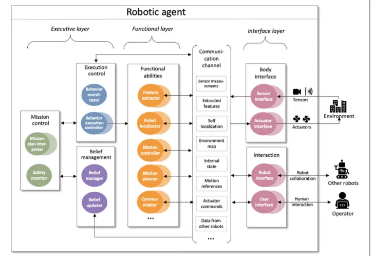
Figure 1 shows the reference architecture of Aerostack as it is defined in the last release (version 3.0). In the figure, circles represent data processing units (or processes in short) that are implemented as ROS nodes (a duplicated circle represents several processes of the same type). Pro-cesses are organized in three main layers: interface, func-tional, and executive. The interface layer includes processes that help interact with the world. They include processes that receive data from sensors or send commands to robot actuators, as well as communication processes with the human operator and other robots.
The other two layers, functional and executive, are com-mon in multilayer architectures of autonomous systems, as can be seen in the LAAS architecture,17Claraty,18or in the general description of Kortenkamp et al.1 The Aerostack architecture uses a standard communication channel, which is implemented with ROS message types that are common in aerial robotics. This channel facilitates process intero-perability and makes the functional and executive layers independent of specific aerial platforms.
The functional layer includes processes for functional abilities of robots. Aerostack provides a library of software components to implement these processes and the devel-oper can use and combine them to build a particular robotic system architecture. For example, there are components implementing recognition algorithms (e.g. recognizer of ArUco markers or quick response (QR) codes), motion controllers (e.g. proportional-integral-derivative (PID) con-trollers for pose control or speed control and trajectory controllers), processes that perform self-localization and mapping (SLAM), motion planners that generate obstacle-free paths to reach destination points, and methods for communicating with other agents (other robots or human operators).
The third layer of the Aerostack architecture is the exec-utive layer and includes processes that execute the mission plan by activating and monitoring the execution of the functional abilities of the functional layer. The executive layer includes three systems that perform the following functions: mission control, execution control, and belief management. The objective of the mission control system is to control the execution of mission plans. This is done using a mission plan interpreter that translates the mission plan into execution requests. There is also a safety monitor that reacts in the presence of unexpected events that require urgent attention.
Both processes, the mission plan interpreter and the safety monitor, generate execution requests that are formu-lated as commands that request to activate or deactivate behaviors. Examples of behaviors in Aerostack aretake off, land, follow path, pay attention to QR codes, and so on. We distinguish between two types of behaviors according to their execution goal. On the one hand, there are behaviors that recurrently perform an activ-ity or maintain a desired state (e.g. pay attention to QR codes). On the other hand, there are behaviors whose exe-cution goal is to reach a final state (e.g. follow path) and they finish their execution once the goal is achieved.
To activate and deactivate robot behaviors, the execu-tive system has a second component, called execution con-trol system,19which translates behavior activation requests into the execution of specific processes. This system also monitors the execution of these processes and communicates the result in terms of success or failure.
The execution control system provides protection against requests that are not compatible with the environ-ment state, checking in advance that each behavior to acti-vate is consistent with the environment situation. The execution control also ensures the consistency of the set
of concurrent processes that support the robot actions. When a behavior is accepted to be active or inactive, the execution control can deactivate and activate other related behaviors.
The third component of the executive system is the belief management system. This component is used as a working memory to store the dynamic data generated dur-ing the execution. This memory filters relevant facts required for decision-making during mission execution. The basic element stored in the memory is abeliefwhich represents a proposition about the world that the robot believes to be true (the world here refers to both the exter-nal world and the interexter-nal state of the robot). The content of the memory is updated periodically (at low frequency) using data from other layers of the Aerostack architecture (functional layer and interface layer).
Software components for building the
executive system
ROS nodes, dashed arrows represent ROS services, and continuous arrows represent ROS topics. In this design, there aregeneralcomponents that are common for different robotic systems (mission plan interpreter, safety monitor,
behavior coordinator, and belief manager). There are also specific components that need to be programmed to develop the executive system of a particular robot (beha-vior execution controllers and belief updater).
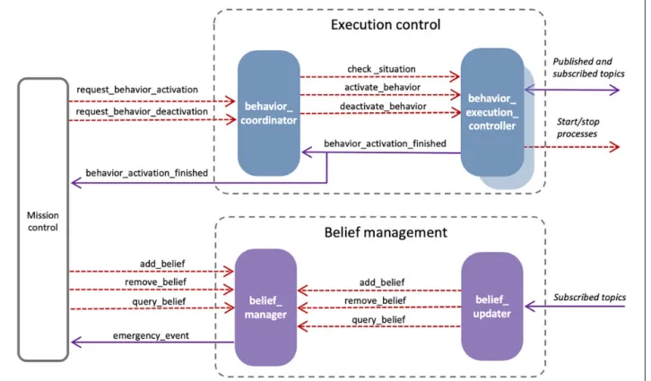
Figure 2.Components of the executive system used in Aerostack.
Figure 3.Detail of components related to execution control and belief management.
Execution control
Figure 3 shows the components of the execution control sys-tem at the upper part of the diagram. This design distributes the execution control in a set of behavior execution controllers (one for each type of behavior) together with a behavior coor-dinator that manages the concurrent execution of behaviors. Behavior execution controllers provide modularity because they encapsulate execution details for each behavior, which helps add new behaviors with flexibility, without affecting other behaviors and the overall execution control mechanisms. Each behavior execution controller is implemented as a separate ROS node that creates a uniform interface to be used by the behavior coordinator. The interface is defined with three request–reply services:
Check situation verifies that the behavior can be activated in the current situation of the environment (e.g. to activate the behavior take off the aerial robot must be landed).
Activate behavior activates the execution of the behavior using certain parameter values.
Deactivate behaviorstops the behavior execution.
When a behavior is activated, the behavior execution controller monitors its execution in order to detect that it works as expected. For example, the execution of the beha-viorTAKE_OFF should finish in a maximum time (time-out). When the behavior finishes, the behavior execution controller sends a message reporting the result of behavior execution, using the ROS topic calledbehavior activation finished, with values such asgoal achieved,timeout,wrong progress,process failure, orinterrupted. This monitoring is a kind of self-reflective functionality that observes the own robot behavior to provide cognizant failure, which is useful to improve the usability and reliability of the final robotic system.
The behavior coordinator works as a central process that handles the concurrent execution of active behaviors. This process responds to behavior activation requests and ensures the consistency of their execution. The behavior coordinator is implemented as a ROS node with two request–reply ROS services to activate and deactivate behaviors called respectively request behavior activation andrequest behavior deactivation. To accept a behavior activation request, the coordinator first checks the consis-tency between the behavior and the state of the environ-ment. This is done by asking the behavior execution controller if the behavior satisfies the conditions of the situation (servicecheck situationdescribed above).
Then, the coordinator verifies that the behavior activa-tion request is consistent with other active behaviors. This verification is done using a method that performs a search process to find a set of activations and deactivations that are consistent with the activation request. This is necessary because it may be possible that the activation of one
behavior requires the activation or deactivation of other behaviors to satisfy the consistency constraints.
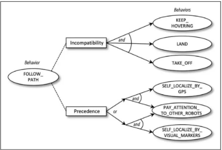
For this verification, the coordinator checks that a set of constraints between active behaviors are satisfied. These constraints are specific to the set of behaviors used in a particular robotic system and they are written by the devel-oper (in a text file using YAML syntax). Constraints express relations about incompatibility and precedence. Figure 4 shows an example that illustrates how these rela-tions are represented for the behaviorFOLLOW_PATH. The rectangle located above in the figure associates a list of behaviors that are not compatible with the behavior FOL-LOW_PATH(two incompatible behaviors cannot be active at the same time). The relation below in the figure expresses precedence constraints using an and/or graph representation. This example means that, before the beha-vior FOLLOW_PATH can be activated, at least one set of behaviors of the two disjunctive options must be active.
Since activations or deactivations can be asked by dif-ferent requesters, the coordinator also uses a priority scheme to avoid conflicts. Each request includes a priority degree expressed with a number associated to each reques-ter. For example, the current implementation of Aerostack uses the following priority degrees: 4 (emergency activa-tion), 3 (manual activaactiva-tion), 2 (activation due to mission plan execution), and 1 (default activation). The activation by default corresponds to behaviors that must be active when there are no other incompatible behaviors active and the current situation is compatible with their activation. These behaviors may be, for example, behaviors that should be active when the robot is not doing any specific action. For instance, in the case of aerial robotics, the beha-viorKEEP_HOVERINGis a default behavior (hovering is a maneuver in which the robot is maintained in nearly motionless flight over a reference point at a constant alti-tude and on a constant heading).
using the services provided by behavior execution control-lers. Requests to deactivate a behavior are analyzed in a similar way before being accepted because, when a beha-vior is deactivated, other behabeha-viors can be activated (e.g. default behaviors). In addition, the coordinator is sub-scribed to the ROS topicbehavior activation finishedthat informs when a behavior has finished its execution (e.g. because it has reached the goal or because it has failed). When this happens, the coordinator removes the behavior from the list of active behaviors and checks if other beha-viors should be activated.
Behavior execution controllers are programmed for each particular control architecture. The developer writes spe-cialized programs (e.g. with algorithms for feature extrac-tion, SLAM, motion control, etc.) and, then, these programs are managed by a ROS node that implements the execution controller. Each execution controller is normally designed to be general in order to be reusable for more than one particular robot. For example, Aerostack provides a library of reusable behavior controllers that are common in aerial robotics.
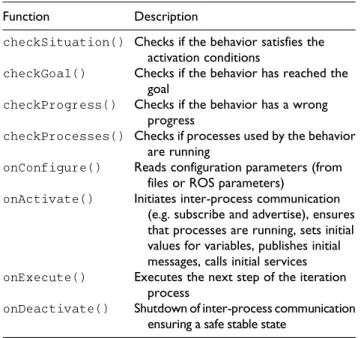
To help developers program a behavior execution con-troller, Aerostack provides a Cþþ class called Beha-viorExecutionController that defines a common interface to be used by the executive system to activate and deactivate behaviors in a uniform way (see Figure 5). Each particular subclass (e.g. a subclass for the behavior
GO_TO_POINT) includes a set of specific functions, which override functions defined in the class, to control the exe-cution of the behavior (see Table 1). For example, the
function checkGoal() for the behavior GO_TO_POINT
verifies that the robot has reached the destination point. In order to improve the efficiency in the consumption of computational resources, we implement behavior execution controllers grouped in behavior systems. For this reason, we use a type of node provided by the ROS library called node-let (http://wiki.ros.org/nodelet). Each behavior execution Figure 5.Cþþclasses to program behavior execution controllers.
Table 1.Specific functions of an execution controller.
Function Description
checkSituation() Checks if the behavior satisfies the activation conditions
checkGoal() Checks if the behavior has reached the goal
checkProgress() Checks if the behavior has a wrong progress
checkProcesses() Checks if processes used by the behavior are running
onConfigure() Reads configuration parameters (from files or ROS parameters)
onActivate() Initiates inter-process communication (e.g. subscribe and advertise), ensures that processes are running, sets initial values for variables, publishes initial messages, calls initial services
onExecute() Executes the next step of the iteration process
onDeactivate() Shutdown of inter-process communication ensuring a safe stable state
ROS: Robot Operating System.
controller class is subclass of nodelet. Each nodelet imple-menting a behavior execution controller belongs to a group of nodelets that form a behavior system. For example, in the current implementation of Aerostack there is a behavior system, called basic_quadrotor_behaviors, that includes
four behaviors: TAKE_OFF, LAND, WAIT, and
SELF_LOCALIZE_BY_ODOMETRY.
Belief management
As explained above, the belief management system works as a working memory that stores dynamic data, needed for mission planning decision-making, that are generated dur-ing mission execution. The basic element stored in the memory is abeliefwhich is represented using logic predi-cates in the general format ofpredicate(object,value) or in a simpler form property(object). Objects are represented with numerical identifiers as instances of a class. For exam-ple,object(32, obstacle)represents that object 32 is an obstacle andcolor(32, blue)represents that object 32 is blue.
Aerostack uses a ROS node called belief manager to store and manage sets of beliefs (Figure 3). The belief manager provides the services add belief, remove belief, andquery belief. The first two services are used to update the content of the memory of beliefs. The service query beliefcan be used to know if a belief is true and to deter-mine the values of parameters. This is done using belief expressions that may include variables. For example, a query with the expression object(?x, battery), charge(?x,?y)can return the values for variables
?x¼92,?y¼fullmatching their corresponding values in the belief memory.
The content of the belief memory can be updated using information from the functional layer (e.g. data related to feature extraction, self-localization, etc.). This is done by a specialized process calledbelief updater, implemented as a ROS node, that abstracts data from the behavior layer and updates a category of beliefs by changing the content of the belief memory. The current version of Aerostack provides a belief updater, that maintains updated a number of basic beliefs that are common for most aerial robots (e.g. beliefs related to the position, flight state, etc.). Developers must adapt this belief updater for each particular application if they need to add other specific beliefs.
The belief manager maintains consistency between beliefs according to their semantic properties. For example, in general, it is assumed that values are mutually exclusive. When a belief is added, for example, charge(92, empty), the incompatible beliefs are automatically retracted, for example,charge(92, full). The belief manager uses a configuration file called belief_mana-ger_config.ymlto express semantic properties about predicates. This file is application specific and can include exceptions to the default semantics. For instance, the
following lines represent that the values of the predicate
content(?x,?y) are not mutually exclusive and the maximum number of different values is five:
- predicate_name: content mutual_exclusive_values: no maximum_values: 5
This file can also include conditions to generate events that require urgent attention. For example, the following lines represent that when a predicate with the form char-ge(?x, low)is added to the belief memory, a message is published through the ROS topic emergency_event
containing such a predicate:
- predicate_name: charge emergency_value: low
Mission control
The objective of the mission control system is to handle the execution of mission plans. Each mission plan is a program written by the developer that specifies the set of tasks that a robot has to perform in a particular mission. For mission control, the executive system in Aerostack uses two types of components that run concurrently (Figure 6): (1) a mis-sion plan interpreter, which translates the mismis-sion plan into a sequence of execution requests following a goal-driven execution, and (2) a safety monitor that reacts in the pres-ence of emergencies following an event-driven execution. The combination of both methods is handled by the behavior coordinator, which receives execution requests from both processes. The separation of the safety monitor from the mission plan interpreter is useful, for example, to simplify how mission plans are formulated because plans do not need to include tasks to cope with situations that are already handled by the safety monitor.
The current version of Aerostack provides two different mission plan interpreters to help developers specify mis-sion plans. The first one is based on a Python Application Programming Interface (API). This is a convenient method for users who are familiar with computer programming languages and provides high flexibility for formulating plans with complex control regimes. The second interpreter uses a graphical approach based on behavior trees. This method is more appropriate for users who are less familiar with programming languages. This interpreter also pro-vides better protection against errors and facilitates pre-emptive interaction between the user and the robot.
of the API. Aerostack provides a ROS node to support this API calledpython-based mission interpreter.
Figure 7 shows a simple example of a mission written in Python using the API provided by Aerostack. In this
example, first, the functionexecuteBehavior()is used to ask the robot to take off. Then, the function queryBe-lief()is used to consult the coordinates of an object that is defined as an instance ofgoal. Next, the coordinates are Figure 6.Detail of components for mission control.
Table 2.Example functions of the Python API.
Function Description
executeBehavior(x,y) Execute a goal-based behaviorxwith argumentsy, and wait until the goal is reached
activateBehavior(x,y) Activate a behaviorxwith argumentsy deactivateBehavior(x) Deactivate the activation of behaviorx
isActiveBehavior(x) Answer whether a behaviorxis active (true) or not (false)
queryBelief(x) Answer if a belief expression matches predicates of the belief memory
addBelief(x) Add a belief expression to the belief memory
removeBelief(x) Remove a belief expression from the belief memory
API: Application Programming Interface.
Figure 7.Simple example of a mission plan specified in Python.
extracted to be stored in variabledestination. Then, the functionexecuteBehavior()is used to move the robot to the destination point. Finally, the same function is used to ask the robot to land.
Mission plan specification using behavior trees. A behavior tree is a visual modeling language that uses a graphical notation to represent the behavior of a system. In robotics, behavior trees have been used recently20 and specifically for unmanned aerial vehicles (UAVs).21,22 Aerostack provides two ROS nodes to operate with behavior trees: (1) an interpreter of behavior trees to execute the mission plan and monitor graphically its execution, and (2) a graphical editor to create the mis-sion plan as a behavior tree. The graphical editor does not operate in runtime, but it is also implemented as a ROS node because it communicates with the behavior coordinator to get information about the available beha-viors and the correct format of their parameters.
Each behavior tree is represented with a hierarchy of executable nodes. Nodes can succeed or fail during the exe-cution of the mission plan. Intermediate nodes of the tree establish the control regime (e.g. a sequence, a loop, etc.). The types of intermediate nodes provided by Aerostack are similar to the nodes provided by common behavior trees:
Sequence. This node executes the child nodes in sequence and succeeds when all the children suc-ceed. Otherwise it fails.
Selector. This node executes the child nodes in sequence and succeeds when one of the children succeeds. If none of them succeeds, it fails.
Parallel.This node executes its child nodes in par-allel. LetNbe the number of child nodes. It returns success if the number of succeeding children is larger or equal than a local constantS, specified by the user. Returns failure if the number of failing children is largerNS.
Repeat. This node repeats the execution of a child node a number of times. Returns success. It can only have one child node.
Repeat until fail. This node repeats the sequential execution of child nodes until a child node fails. This node always succeeds.
Inverter.This node returns failure if the child node succeeds. Otherwise it succeeds.
Succeeder.This node executes its child node and, no matter what is the result of the execution, it always succeeds.
In Aerostack, leaf nodes of a behavior tree correspond to operations related to behaviors and beliefs in the following way:
Behavior operation node.A behavior operation node is used to activate or deactivate a behavior. There is a node that executes a behavior which succeeds
when its goal is accomplished and fails if it is not possible (this is a usual node in general behavior trees). In Aerostack, there are also other operation nodes to control behaviors that are activated to oper-ate concurrently: (1) a node that activoper-ates a behavior, which succeeds if the behavior is correctly activated (without waiting to reach a goal), and (2) a node that deactivates an active behavior, which succeeds if the behavior is correctly deactivated.
Belief operation node. A belief operation node inter-acts with the belief memory of Aerostack to add, remove, or query belief expressions. A node that adds a belief expression succeeds if the belief is correctly added. A node that removes a belief expression from the memory succeeds if the belief is correctly removed. A node that queries the mem-ory is formulated with a belief expression with a set of predicates. This node succeeds if the belief expression matches the predicates that are present in the belief memory.
Behavior trees in Aerostack can use variables to com-municate information between leaf nodes. For example, there can be a belief operation node in a mission plan to consult the coordinates of the current position of the robot. This node can use the following belief expression: posi-tion(self,(?X,?Y,?Z)). In this expression, X, Y,
andZare preceded by a question mark (?)to represent that they are variables. When this node is executed, the expression matches the corresponding predicate in the belief memory. For example, if the belief memory has the predicateposition(self, (2.1, 3.2, 4.8)), the variables get the values X ¼ 2.1, Y ¼ 3.2, Z ¼ 4.8.The values of these variables can be used by other nodes of the mission plan. For instance, there may be an operation node in another place of the same mission plan that uses the behavior GO_TO_POINTwith the following argument:coordinates: [þX,þY,þZ]. The sign plus (þ) as a prefix of the variable name indicates that the vari-able will be substituted during the execution by the value that the variable has in this moment. Considering the pre-vious example, this means that the robot will go to a desti-nation with the coordinates(2.1, 3.2, 4.8).
To execute the behavior tree, the interpreter loads the YAML file with the mission plan and it follows its structure to generate a sequence of activations and deactivations of robot behaviors. During the execution, the interpreter shows a window that presents graphically the dynamic evolution of the execution and the current values of variables used by the behavior tree. The interpreter also facilitates preemptive interaction between the user and the robot, that is, the user can interrupt the mission at any point and continue the exe-cution in another node of the behavior tree.
Experimental tests
This section describes the evaluation procedure that we conducted to analyze the effectiveness of the solution pre-sented in this article. This evaluation was carried out by analyzing an aerial robotic system that was built using the software components presented in this article. The evalua-tion procedure pays attenevalua-tion to the trade-off between
benefits for the final system and the costs related to devel-opment effort and performance efficiency.
Table 3 shows the quality characteristics analyzed in the evaluation procedure. To select these characteristics, we used the definitions used by the international standard ISO/IEC 25010:2011 (https://www.iso.org/obp/ui/#iso:std:iso-iec: 25010:ed-1:v1:en), considering the following aspects: devel-opment effort (which was analyzed by observing the amount of code reused in relation to the amount of new code pro-grammed), performance efficiency (time behavior and resource utilization), and benefits for the final system (user protection and fault tolerance). The following sections pres-ent the details and results of this evaluation procedure.
Development effort
This section describes the work that was done to evaluate how much Aerostack reduces the effort of building the executive system of a particular aerial robotic system. The Figure 8.Example of behavior tree as it is displayed graphically by the editor.
Table 3.Quality characteristics analyzed in the evaluation procedure.
Evaluated characteristic Definition (ISO/IEC 25010:2011)
Reusability Degree to which an asset can be used in more than one system, or in building other assets
Time behavior Degree to which the response and processing times and throughput rates of a product or system, when performing its functions, meet requirements
Resource utilization Degree to which the amounts and types of resources used by a product or system, when performing its functions, meet requirements
User error protection Degree to which a system protects users against making errors
Fault tolerance Degree to which a system, product, or component operates as intended despite the presence of hardware or software faults
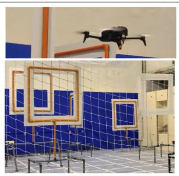
system developed was based on the competition Autono-mous Drone Race of IROS 2018 (International Conference of Intelligent Robots and Systems). This competition is a race with indoor autonomous flight challenges (e.g. frames to cross). In the experiments, we used a simplified version of this mission with four frames to cross (with different orien-tations and different heights). The aerial robot performs autonomously the mission, knowing in advance approximate locations of frames and using visual recognition to find the detailed position of frames before crossing them.
Figure 9 shows the area that we used for experimental flights with frames to cross. In these tests, we used an aerial vehicle Parrot Bebop 2, and a laptop computer with the fol-lowing features: CPU Intel i7-7700HQ, 8 cores, 2.8 GHz, and 16 GB RAM. Figure 10 shows an example of a real flight. The figure also shows the sequence of the first five behaviors (TAKE_OFF, GO_TO_POINT, etc.) with references to the point of the trajectory where they are activated. In this case, the aerial robot spent 117.1 s to complete the mission.
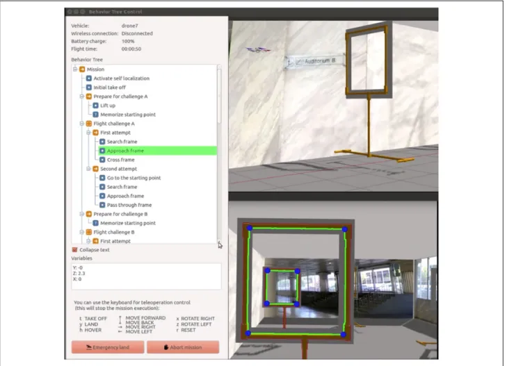
For some experiments, we also performed simulated missions using a computer with the following features: CPU Intel i5-4460, 4 cores 3.2 GHz, and 16 GB RAM. Figure 11 shows a screen snapshot corresponding to the execution in one of the experiments using the Rotors simulator.23 The image shows the behavior tree viewer on the left. On the right, the figure shows the 3D image generated by Rotors and, at the bottom, the image obtained by the front camera of the drone (showing with green color the frames recognized by the computer vision algorithm).
The main tasks performed for building the executive system for this robotic system were the following:
1. Programming new execution controllers. We pro-grammed several behavior execution controllers for the new motion behaviors used in this robot. This corresponds to the following behaviors (see Table 4): SEARCH_FRAME, APPROACH FRAME, SELF_LOCALIZE,andMOVE_FORWARD.
2. Reusing software for execution control. Some of the execution controllers had been already programmed in previous projects, so they were available in Aero-stack as reusable components. This corresponds to the following behaviors (see Table 4): GO_TO_-POINT, ROTATE, KEEP_HOVERING, TAKE_-OFF,andLAND.
3. Configure common modules. This task corresponds to the configuration of the common ROS nodes corresponding of the executive system (e.g. beha-vior coordinator, mission plan interpreters, etc.). For example, the file of the behavior catalog was extended to include the new behaviors and the mission plan was written using both the Python API and the behavior tree editor to compare both approaches.
We evaluated reusability in this development, consider-ing the degree to which Aerostack was used in buildconsider-ing the executive system of the robotic system. The number of lines corresponding to the common components of Aero-stack for executive systems is 13,519 lines, which includes: behavior tree interpreter, Python-based mission interpreter, behavior tree editor, behavior coordinator, belief manager, and class behavior process. Several behavior execution controllers were also reused (for behaviors GO_TO_-POINT, ROTATE, KEEP_HOVERING, TAKE_OFF, and
LAND) which corresponds to 1915 lines. The execution controllers for the new behaviors (SEARCH_FRAME, APPROACH_FRAME, SELF_LOCALIZE, and
MOVE_FOR-WARD) have in total 2839 lines. These numbers show that a large part of the code of the executive system (84%) corre-sponds to Aerostack code that was reused. Only a small fraction (16%) was needed to be programmed as new code for the executive system.
Figure 9.The aerial robot and the flight area used for experi-mental tests.
Computational cost of the executive system
The computational cost of the executive system developed with Aerostack was evaluated by measuring its perfor-mance efficiency in terms of time behaviorand resource utilization. We estimated the processing time of the exec-utive system in the following way. During the mission
execution, a sequence of behavior activations is generated b1;. . .;bn
f g(wherenis the number of behavior activations requested in a mission plan). The variables used are:
Mission control time s: arithmetic mean of s1;s2. . .; snwheresiis the time from the moment a behaviorbi1 has finished its execution until the
Figure 11.Screen snapshot corresponding to one of the experiments using the behavior tree interpreter (on the left) and the simulator Rotors (on the right).
Table 4.Motion behaviors used in the robotic system.
Behavior Description
SEARCH_FRAME The robot searches for a frame by doing certain movements. The robot uses a visual recognition algorithm to detect the presence of the frame
APPROACH_FRAME The robot approaches the frame using a visual servoing method to be in front of the frame ready to cross it
MOVE_FORWARD The robot moves forward a certain distance. This behavior uses a simple open-loop controller that is used to cross quickly the frame
GO_TO_POINT The robot goes to a 3D point defined by spatial coordinates (x,y,z)
ROTATE The robot rotates left or right a certain number of degrees (angle) on the vertical axis (yaw)
TAKE_OFF The robot takes off vertically from a static surface. This behavior ends when the robot reaches a default altitude
LAND The robot lands vertically in the current position. This behavior assumes that the ground is static
KEEP_HOVERING The robot is maintained in nearly motionless flight over a reference point at a constant altitude and on a constant heading
SELF_LOCALIZE The robot determines the coordinates corresponding to its location using information from sensors (e.g. IMU and camera images)
moment the behavior coordinator receives a mes-sage that requests to activate the next behavior bi. During this time, the mission plan interpreter deter-mines the next behavior to activate.
Coordination time t: arithmetic mean of t1;t2;. . .; tnwheretiis the time from the moment the behavior coordinator receives a message that requests to activate behaviorbiuntil the moment the coordinator has determined the set of behaviors to activate and deactivate.
Activation time ’: arithmetic mean of’1; ’2;. . .; ’nwhere’iis the time from the moment the beha-vior coordinator has determined the set of behabeha-viors to activate and deactivate (as a response to the request to activate the behaviorbi), until the moment all these activations and deactivations are completed by the corresponding behavior execution controllers. During the activation of a behavior, the execution controller (1) creates ROS objects for inter-process communication such as subscribers, publishers, and service clients, (2) starts the execution of processes, and (3) initiates the execution control (e.g. set initial values of variables, publish initial messages, and call initial services). During the deactivation of a beha-vior, the execution controller may unsubscribe ROS topics, disconnect service clients, and stop running processes.
Table 5 shows the results obtained for these variables. The experiments were done with a mission plan withn ¼
20. The mission plan was represented using two alternative options, the Python API and a behavior tree. The results show that the Python-based mission interpreter consumes more time than the behavior tree interpreter for mission control. For the behavior tree interpreter this value iss¼ 4:4 ms and for the Python-based mission interpreter this value is s¼ 54:8 ms, which corresponds to a difference of 50.4 ms. This difference may be explained by the fact that the Python-based mission interpreter uses the general interpreter of the Python language, which requires additional computa-tion. The behavior tree interpreter is programmed in Cþþ
and does not use the Python interpreter.
Table 5 also presents the results corresponding to coor-dination timet. As expected, values are similar for both the Python mission and the behavior tree mission. The values aret¼1.8 ms for the behavior tree andt¼1.1 ms for the Python mission.
Table 5 indicates that a significant part of the processing time corresponds to the activation time’of behavior exe-cution controllers, which has similar values with the beha-vior tree and with the Python mission (41.9 and 45.2 ms, respectively). This time depends on each particular appli-cation and it is affected by the number of ROS objects created for inter-process communication (e.g. subscribers, publishers, and service clients) and the number of processes that are started and stopped.
In general, the results show that the use of the general components of the executive system adds a delay estimated assþt¼6.2 ms/behavior (using the behavior tree) ands þt¼53.2 ms/behavior (using Python). If we consider also the time used by the specific behavior execution controllers developed for this system the total delay issþt þ’¼
48.1 ms/behavior (using the behavior tree) and s þ t þ
’¼98.4 ms/behavior (using Python).
Concerning resource utilization, Table 6 shows CPU usage and memory usage of different processes related to the executive system. Regarding CPU usage, both the beha-vior tree and Python obtain similar values (12.1% and 11.8%). In the case of memory usage, the behavior tree obtains a lower value (43.7 MiB) than the value obtained by behavior trees (76 MiB) which is explained by the mem-ory usage required by the processpython2 (general inter-preter of Python language). In general, these results are considered acceptable. The generic processes, in particular, obtain good values with measures for the behavior tree: CPU usage of 4.7%and memory usage of 18.7 MiB.
Besides these measures, it is important to note that each ROS node consumes additional resources due to the use of node launchers (processroslaunch). According to our mea-sures, the average use of each launcher consumes 47.8 MiB of memory and 0.3% of CPU usage. This consumption justifies using behavior systems that integrate groups of behavior execution controllers as nodelets, instead of sep-arate ROS nodes. In our case, two behaviors systems (with four behaviors each system) use two launchers (which means 95.6 MiB and 0.6%), while using eight separate behaviors would use eight launchers (i.e. 382.4 MiB and 2.4%).
Usability and reliability of the final robotic system
This section describes the evaluation conducted to analyze the benefits that the final robotic system obtains by having the executive system developed using Aerostack. We Table 5.Results obtained in the experiments about processing time (values in ms).
Variable Description Behavior tree,B Python,P Difference, |BP|
s Mission control time 4.4 54.8 50.4
t Coordination time 1.8 1.1 0.7
’ Activation time 41.9 45.2 3.3
Sumsþt 6.2 53.2 47.0
considered here two characteristics: user error protection and fault tolerance. To assess user error protection, we manually constructed a testsite with a representative set of potential errors that users can make when they specify a mission plan. This testsite includes local errors (category A) related to simple lexical error (subcategory A.1) or syn-tax errors (subcategory A.2). This category also includes errors related to wrong values for parameters (subcategory A.3). We determined types of local errors by analyzing the representation used by the mission specification method. The testsite also includes other errors (category B) related to the global consistency of the mission (consistency between different tasks B.1 or consistency between tasks and the environment B.2). In this case, we identified types
of errors by analyzing the interaction between robot beha-viors and the interaction between robot behabeha-viors and the environment. We created manually examples of these error types and were included in the testsite.
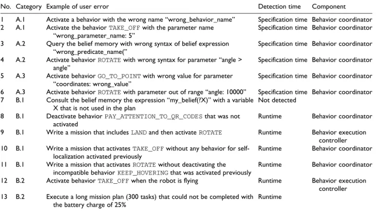
Table 7 shows a sample of tests corresponding to the testsite and how they are detected. The columndetection timeindicates when the error is detected: during specifi-cation time or in runtime. The column component indi-cates the main component of the executive system that is used to detect the error. All user errors corresponding to category A are detected during specification time using information provided by the behavior coordinator. These errors are detected during the construction of a mission plan using the behavior tree editor (the Phyton API does Table 6.Results obtained in the experiments about resource utilization.
Processes (ROS nodes)
CPU usage, behavior tree (%)
CPU usage, Python (%)
Memory usage, behavior tree (MiB)
Memory usage, Python (MiB)
Behavior coordinator 0.3 0.3 1.3 1.3
Belief manager 0.3 0.3 1.0 1.0
Belief updater 2.0 2.0 1.0 1.0
Safety monitor 0.1 0.1 1.0 1.0
Behavior tree interpreter 2.0 14.4
Process “python2” 0.7 47.4
Sum 4.7 3.4 18.7 51.7
Behavior system with four basic behaviors 3.2 3.2 12.4 12.4 Behavior system with four motion behaviors 5.2 5.2 12.6 12.6
Sum 12.1 11.8 43.7 76.7
ROS: Robot Operating System.
Table 7.Sample of tests performed to analyze user error protection.
No. Category Example of user error Detection time Component
1 A.1 Activate a behavior with the wrong name “wrong_behavior_name” Specification time Behavior coordinator 2 A.1 Activate the behaviorTAKE_OFFwith the parameter name
“wrong_parameter_name: 5”
Specification time Behavior coordinator
3 A.2 Query the belief memory with wrong syntax of belief expression “wrong_predicate_name(”
Specification time Behavior coordinator
4 A.2 Activate behaviorROTATEwith wrong syntax for parameter “angle > angle”
Specification time Behavior coordinator
5 A.3 Activate behaviorGO_TO_POINTwith wrong value for parameter “coordinates: wrong_value”
Specification time Behavior coordinator
6 A.3 Activate behaviorROTATEwith parameter out of range “angle: 10000” Specification time Behavior coordinator 7 B.1 Consult the belief memory the expression “my_belief(?X)” with a variable
X that is not used in the plan
Not detected
8 B.1 Deactivate behaviorPAY_ATTENTION_TO_QR_CODESthat was not activated
Runtime Behavior coordinator
9 B.1 Write a mission that includesLANDand then activateROTATE Runtime Behavior execution controller 10 B.1 Write a mission that activatesTAKE_OFFwithout any behavior for
self-localization activated previously
Runtime Behavior coordinator
11 B.1 Write a mission that activatesROTATEwithout deactivating the incompatible behaviorKEEP_HOVERINGthat was activated previously
Runtime Behavior coordinator
12 B.2 Activate behaviorTAKE_OFFwhen the robot is flying Runtime Behavior execution controller 13 B.2 Execute a long mission plan (300 tasks) that could not be completed with
the battery charge of 25%
Runtime
not provide protection for any of these errors during spe-cification time).
During the execution of the mission, errors correspond-ing to category B are detected in the followcorrespond-ing way. Error 7 is not detected because it does not affect to the execution. Errors 8 and 10 are correctly detected and reported by the behavior coordinator. Error 11 is correctly detected and solved by the behavior coordinator deactivating the incom-patible behavior. Errors 9 and 12 are correctly detected by behavior execution controllers (checking the conditions about the situation). In the case of error 13, the robot lands when the battery is discharged (this is a low-level safety mechanism independent of the executive system).
These tests show that the majority of these errors are detected and avoided with the help of the executive system, which provides an important protection against wrong and dangerous behaviors. However, it would be desirable that the executive system would detect all these errors when the operator specifies the plan, before the mission is executed. To assess fault tolerance, we constructed a testsite with a representative set of unexpected events. Tests are divided into the following categories: (C) software errors (D),
hardware faults, and (E) interruptions caused by the oper-ator or the safety monitor (e.g. caused by unexpected situa-tions in the environment). Tables 8 and 9 show samples of tests corresponding to this testsite. In the majority of the cases, the execution of these tests show that the executive system is able to avoid a generalized failure, maintaining a limited functionality. Most of the problems are detected and the failure is correctly reported.
Concerning events of category C, which are software errors that affect components of the control architecture, behavior execution controllers detect correctly events 1–4 and the mission continues normally to perform the next task. However, the response to events 5 and 6 is not satis-factory because the events are not detected and the mission execution is blocked. This is because these errors affect directly to the components of the executive system. In this case, an additional separate solution should be used to monitor and verify the correct the execution of the execu-tive system.
Events of category D (hardware faults) are correctly detected by behavior execution controllers (events 7 and 8). However, hardware faults that require a rapid reaction Table 8.Sample of tests performed to analyze fault tolerance (software and hardware faults).
No. Category Unexpected event during execution How is the event detected?
How does the robot behave?
How does the mission continue?
1 C BehaviorGO_TO_POINTis executed with a bug error in motion planning (infinite loop)
The execution controller detects timeout and terminates the behavior reporting failure
Robot does not perform what is expected (remains still in the same position)
Mission continues to perform next task
2 C The timeout specified for the behavior
ROTATEis too sort
The execution controller detects timeout and terminates the behavior reporting failure
Robot does not perform what is expected (it does not complete the motion)
Mission continues to perform next task
3 C The ROS node for motion control terminates unexpectedly while the behaviorGO_TO_POINTis active
The execution controller detects process failure and terminates the behavior reporting failure
Robot does not perform what is expected (it keeps moving without stopping)
Mission continues to perform next task
4 C ROS node for motion planning terminates unexpectedly while the behaviorGO_TO_POINTis active
The execution controller detects process failure and terminates the behavior reporting failure
Robot performs what is expected
Mission continues to perform next task
5 C Behavior execution controller of
GO_TO_POINTis blocked (executes an infinite loop) while the behavior
GO_TO_POINTis active
This event is not detected. The execution controller
does not inform that the behavior has finished
Robot performs what is expected
Mission is blocked
6 C The behavior coordinator is blocked (executes an infinite loop) and, then, behaviorGO_TO_POINTis requested to be active
This event is not detected. BehaviorGO_TO_POINTis
not activated
Robot does not perform what is expected (remains still in the same position)
Mission is blocked
7 D The camera is broken while the behaviorGO_TO_POINTis active
The execution controller detects process failure and terminates the behavior reporting failure
Robot does not perform what is expected (uncontrolled movement)
Mission continues to perform next task
8 D A rotor is broken while the behavior
GO_TO_POINTis active
The execution controller detects wrong progress and terminates the behavior reporting failure
Robot does not perform what is expected (uncontrolled movement)
(e.g. event 8) should be managed by lower level processes operating at high frequencies to avoid or mitigate danger-ous effects of uncontrolled behaviors.
Events of category E (interruptions) are also correctly managed by the behavior coordinator (events 9–14) to avoid the execution of incompatible behaviors. The beha-vior tree interpreter was used here (event number 10) to stop and continue the mission execution in a different point (the Python-based mission interpreter does not provide this functionality).
Interpretation of evaluation results
The evaluation results show the costs and benefits of using Aerostack for building the executive system of an aerial robotic system. The main conclusions of this evaluation can be summarized as follows:
A large amount of Aerostack code was reused com-pared to the new code programmed.The size of the code reused to develop the executive system of an aerial robot was 15,434 lines and the size of the new
code programmed was 2839 lines, which is a high percentage of code reused (84%).
The performance efficiency of the methods provided by Aerostack for mission plan execution was accep-table in aerial missions. The use of the executive system generates an average delay of 48.1 ms/beha-vior (using the behams/beha-vior tree interpreter) and 98.4 ms/behavior (using the Python-based mission inter-preter). In missions that activate behaviors at low frequencies (less than 0.2 Hz, as it happens in mis-sions used in our experiments) we consider that a delay of less than 100 ms/behavior is admissible, since it would increase the total time to complete the mission in less than 1%(in the case of a Python mission, this increase is around 2%). This is partic-ularly acceptable in missions where time is not crit-ical and high degrees of usability and reliability are required (e.g. inventory missions, inspection mis-sions, etc.).
The processing times of methods provided by Aero-stack for mission plan specification are different. The processing time for executing missions plans Table 9.Sample of tests performed to analyze fault tolerance (interruptions).
No. Category Interruption How is the interruption managed?
How does the robot behave?
How does the mission continue?
9 E The operator stops the execution of a mission plan when the drone is executing the behavior
GO_TO_POINTrequested by the mission interpreter
The behavior coordinator deactivates behavior
GO_TO_POINTand activates
KEEP_HOVERING(by default)
Robot performs what is expected (finishes the movement and keeps hovering)
Mission is stopped correctly
10 E While the mission is paused, the operator forces to continue the execution in another point of the mission plan
The behavior coordinator deactivates behavior
KEEP_HOVERING
Robot performs what is expected
Mission continues to perform next task
11 E The operator requests to activate behaviorGO_TO_POINTwith destination A while the drone is executing the behavior
GO_TO_POINTwith destination B requested by the mission planer
The behavior coordinator deactivates behavior
GO_TO_POINTwith destination B and activates correctly the other behavior
Robot performs what is expected
Mission is stopped correctly
12 E The safety monitor requests to activate behavior
KEEP_HOVERING(because the visibility decreases considerably) while the drone is executing the behaviorGO_TO_POINT
requested by the mission planer
The behavior coordinator deactivates behavior
GO_TO_POINTand activates correctly behavior
KEEP_HOVERING
Robot performs what is expected (finishes the movement and keeps hovering)
Mission is stopped correctly
13 E The operator requests to activate behavior ROTATE while the drone is executing the behavior
GO_TO_POINTrequested by the safety monitor
The behavior coordinator rejects the request from the operator because the request from the safety monitor has more priority
Robot performs what is expected
The emergency plan continues its execution
14 E The operator requests to deactivate behaviorSELF_LOCALIZEwhile the drone is executing the behaviorGO_TO_POINT
requested by the safety monitor
The behavior coordinator rejects the request from the operator becauseSELF_LOCALIZEis precedence ofGO_TO_POINT
Robot performs what is expected
The emergency plan continues its execution
is different for the behavior tree interpreter and the Python-based mission interpreter. The time spent is 4.4 ms/behavior using the behavior tree and 54.8 ms/ behavior using Python. As it was mentioned, this difference may be explained by the fact that Python missions use the general interpreter of the Python language, which requires additional computation (the behavior tree interpreter is programmed in Cþþ).
The behavior tree editor increases user error pro-tection during specification time. The behavior tree editor is able to avoid user errors corresponding to syntax errors and certain semantic errors (wrong names and wrong types of values) during specifica-tion time, using informaspecifica-tion provided by the beha-vior coordinator. In contrast, the Python-based mission interpreter does not detect the presence of these errors before the mission is executed.
The executive system increases user error protection about errors related to global consistency during execution time.User errors related to global consis-tency are detected by the executive system during the mission execution, which is useful to improve usability and avoid dangerous behaviors. However, in order to avoid starting the execution of mission plans that have specification errors, these errors should be detected in advance, when the developer specifies the plan.
The executive system increases fault tolerance.The executive system detects the presence of problems produced by unexpected events (e.g. software errors, hardware faults, and interruptions) and continues the normal execution of the mission. However, there are certain kind of events (e.g. some hardware faults or software errors that affect directly the executive sys-tem) that need additional mechanisms for fault tolerance.
The executive system facilitates preemptive interac-tion between the user and robot. Interruptions are correctly managed by the system with the help of the behavior coordinator and mission plan inter-preters. The behavior tree interpreter is more flexible than the Python-based mission interpreter because the user can stop and continue the mission execution in a different point of the behavior tree. This func-tionality is not provided by the Python-based mis-sion interpreter.
Related work
This section analyzes the similarities and differences of the solution described in this article with existing tools. The analysis has focused mainly on available open-source tools. One of the distinctive characteristics of the tool described in this article is the way it separates the execution control of
a mission plan into simpler processes that run concurrently. For example, the mission plan interpreter is executed sep-arately from the safety monitor and the combination of both methods is handled by a behavior coordination process that also accepts operator interruptions.
Part of the functionality provided by our coordination method is similar to the functionality of Request and Resource Checker (R2C)24 based on the LAAS architec-ture.17Both methods verify execution requests before they are accepted, which is useful to facilitate reliability. How-ever, R2C does not manage multiple execution requesters and it uses a different verification algorithm. Besides, we have not found its implementation in an open-source soft-ware tool that is available for developers.
To translate a mission plan into low-level commands, a usual approach followed by the executive system is to have a uniform interface to operate with the multiple robot func-tions necessary for autonomous behavior (e.g. feature extraction, SLAM, motion control, etc.). The way this uni-form interface is implemented varies in different software tools.
For example, FlexBE5 uses the concept of state and implements the uniform interface as a state with a life cycle (http://wiki.ros.org/flexbe/Tutorials/The%20Sta-te%20Lifecycle) using a Python class (calledEventState) with common functions. The software toolbox CRAM8 usesprocess modulesimplemented as Lisp programs that encapsulate functions executing ROS nodes. The tool ROS-Plan7usesactionsthat are implemented with the help of a Cþþclass (calledRPActionInterfaceClass). The software tool Genom25 usesmodules that are generated automati-cally (in language C) for control architectures based on the LAAS architecture.
In contrast to these tools, our method uses the notion of behaviorthat has been commonly used in behavior-based systems in robotics26,27and as a basic concept for specify-ing mission plans.28,29 In our case, a mission plan is expressed with operations that activate and deactivate behaviors. The uniform interface is implemented with a behavior execution controller which is similar to other solutions to manage the life cycle execution of a process. For example, ROS 2 uses managed nodes(https://design. ros2.org/articles/node_lifecycle.html), that is, nodes with a managed life cycle and FlexBE uses a similar idea although it is applied to the concept of state. The main difference with these solutions is that a behavior execution controller is specialized in the execution of a behavior, instead of a general process or a general state, and includes specialized functions to verify its correct execution.
representation (e.g. automated deduction) that are provided by other approaches in robotics such as KnowRob.30
Concerning the representation language used to specify mission plans, software tools use different methods. For instance, there are tools that formulate mission plans using representations based on finite state machines such as SMACH,2 rFSM,3RAFCON,4and FlexBE.5Some tools use behavior trees such as the ROS behavior_tree package6 and BehaviorTree.CPP (MOOD2Be Project). The previous version of Aerostack (version 2.0) included a task-based approach to represent mission plans represented using the TML language.31 An imperative language like Python is used by PyRobots32to formulate mission plans.
In the method presented in this article, mission plans can be formulated as a Python program using a Python API that provides functions to activate/deactivate behaviors and access the belief memory. The mission plan can also be formulated using a Cþþ program using ROS services. Alternatively, the mission plan can be specified as a beha-vior tree. Our behabeha-vior tree representation is similar to the representation used by other tools although, as a main dif-ference, our method is integrated with the executive sys-tem, so that it can perform queries to a belief memory (using variables that communicate information between tree nodes) and it includes operations to activate and deac-tivate behaviors that operate concurrently.
The method presented in this document assumes that the mission plan is provided as input, that is, the mission plan is either specified by a human developer or generated by an external automated planner, not included in our model of executive system. For this reason, our work has paid atten-tion to include protecatten-tion methods against specificaatten-tion errors. Other software tools use automated reasoners and symbolic languages that are useful to generate mission plans. For example, CRAM8 uses Lisp language and, among other components, includes an automated reasoner based on Prolog. ROSPlan7uses PDDL language and an automated planner to generate mission plans.
Conclusions
This article has presented results of recent advances in the Aerostack software framework to address issues related to safety and efficiency, which may be critical in the case of aerial robots. The article has described a solution to help developers build the executive system of an autonomous robot. The solution is presented as a model of executive system formulated as a general software architecture and a set of reusable open-source components that perform exec-utive functions. The architecture uses an original design that divides the execution control of a mission plan into different processes with separate functions (plan interpre-tation, safety monitoring, behavior coordination, belief management, etc.). This model is now part of the Aerostack it is publicly available as open-source software.
The article presents the evaluation of the solution with an aerial robotic system analyzing the trade-off between benefits (about usability and reliability) and costs (about development effort and performance efficiency). As it is shown by the results, our solution improves the final robotic system in terms of better user error protection and fault tolerance. The evaluation shows that these benefits are obtained with acceptable development effort and computa-tional cost.
The evaluation also shows that there are issues related to usability and reliability that are not fully covered by our solution. For example, our method detects critical errors about global consistency during the mission execution, but it would be better to detect these errors in advance, when the developer specifies the plan. Part of our future research work is oriented to give an answer to this issue by repre-senting explicitly semantic properties of mission plans that are used by automatic validation methods, considering also the practical costs of its use.
Another issue that is not covered by the solution pre-sented in this article is a protection mechanism against errors that affect directly the executive system. In this case, additional protection methods should be considered. For example, a possible solution would be to add a new func-tionality to the behavior coordinator (which is a stable component with low probability of failure) to supervise the execution of the behavior execution controllers (which have higher probability of failure since they are dependent on the final application).
Declaration of conflicting interests
The author(s) declared no potential conflicts of interest with respect to the research, authorship, and/or publication of this article.
Funding
The author(s) disclosed receipt of the following financial support for the research, authorship, and/or publication of this article: Part of the work presented in this article has been developed as a project supported by the European Union’s Horizon 2020 Research and Innovation Program under the Project ROSIN (no. 732287). This work has also received funding from the Spanish Ministry of Science, Innovation and Universities through the proj-ect RTI2018-100847-B-C21.
ORCID iD
Martin Molina https://orcid.org/0000-0001-7145-1974
References
1. Kortenkamp D, Simmons R, and Brugali D. Robotic systems architectures and programming. In: Siciliano B and Khatib O (eds) Springer handbook of robotics. Heidelberg: Springer, 2016, pp. 187–206.
2. Bohren J and Cousins S. The SMACH high-level executive [ROS news].IEEE Robot Autom Mag2010; 17(4): 18–20.
3. Klotzbu¨cher M and Bruyninckx H. Coordinating robotic tasks and systems with rFSM statecharts.J Softw Eng Robot2012; 3(1): 28–56.
4. Brunner SG, Steinmetz F, Belder R, et al. RAFCON: a gra-phical tool for engineering complex, robotic tasks. In:2016 IEEE/RSJ international conference on intelligent robots and systems (IROS), Daejeon, Korea, 9–14 October 2016, pp. 3283–3290. IEEE.
5. Schillinger P, Kohlbrecher S, and von Stryk O. Human-robot collaborative high-level control with application to rescue robotics. In:2016 IEEE international conference on robotics and automation (ICRA), Stockholm, Sweden, 16–21 May 2016, pp. 2796–2802. IEEE.
6. Colledanchise M and Ogren P. How behavior trees modular-ize hybrid control systems and generalmodular-ize sequential behavior compositions, the subsumption architecture, and decision trees.IEEE Trans Robot2017; 33: 372–389.
7. Cashmore M, Fox M, Long D, et al.Rosplan: planning in the robot operating system. In:Twenty-fifth international confer-ence on automated planning and scheduling, Jerusalem, Israel, 7–11 June 2015. Association for the Advancement of Artificial Intelligence. https://www.aaai.org/ocs/index.php/ ICAPS/ICAPS15/paper/view/10619/10379 (accessed 26 May 2020).
8. Beetz M, Mo¨senlechner L, and Tenorth M.CRAM—a cogni-tive robot abstract machine for everyday manipulation in human environments. In:2010 IEEE/RSJ international con-ference on intelligent robots and systems, Taipei, Taiwan, 18–22 October 2010, pp. 1012–1017. IEEE.
9. Guiochet J, Machin M, and Waeselynck H.Safety-critical advanced robots: a survey. Robot Auton Syst 2017; 94: 43–52.
10. Sanchez-Lopez JL, Molina M, Bavle H, et al. A multilayered component-based approach for the development of aerial robotic systems: the Aerostack framework.J Intell Robot Syst 2017; 88: 683–709.
11. Suarez Fernandez RA, Sanchez-Lopez JL, Sampedro C, et al. Natural user interfaces for human-drone multimodal interac-tion. In:International conference on unmanned aircraft sys-tems, Arlington, VA, USA, 7–10 June 2016, pp. 1013–1022. IEEE.
12. Molina M, Frau P, and Maravall D. A collaborative approach for surface inspection using aerial robots and computer vision.Sensors2018; 18(3): 893.
13. Sampedro C, Bavle H, Sanchez-Lopez JL, et al. A flexible and dynamic mission planning architecture for UAV swarm coordination. In:International conference on unmanned air-craft systems (ICUAS), Arlington, VA, USA, 7–10 June 2016, pp. 355–363. IEEE.
14. Rodriguez-Ramos A, Sampedro C, Bavle H, et al. Towards fully autonomous landing on moving platforms for rotary unmanned aerial vehicles. In: International conference on unmanned aircraft systems (ICUAS), Miami, FL, USA, 13– 16 June 2017, pp. 170–178. IEEE.
15. Sampedro C, Rodriguez-Ramos A, Bavle H, et al. A fully-autonomous aerial robot for search and rescue applications in
indoor environments using learning-based techniques.J Intell Robot Syst2018; 95: 601–627.
16. Bavle H, Sanchez-Lopez JL, de la Puente P, et al. Fast and robust flight altitude estimation of multirotor UAVs in dynamic unstructured environments using 3D point cloud sensors.Aerospace2018; 5(3): 94.
17. Alami R, Chatila R, Fleury S, et al. An architecture for auton-omy.Int J Robot Res1998; 17(4): 315–337.
18. Volpe R, Nesnas I, Estlin T, et al. The CLARAty architecture for robotic autonomy. In:Proceedings of the IEEE aerospace conference, Big Sky, MT, USA, 10–17 March 2001. IEEE. 19. Molina M, Camporredondo A, Bavle H, et al. An execution
control method for the Aerostack aerial robotics framework. Front Inform Technol Electron Eng2019; 20: 60–75. 20. Marzinotto M, Colledanchise M, Smith C, et al. Towards a
unified behavior trees framework for robot control. In:2014 IEEE international conference on robotics and automation (ICRA), Hong Kong, China, 31 May–5 June 2014, pp. 5420–5427. IEEE.
21. Ou¨gren P. Increasing modularity of UAV control systems using computer game behavior trees. In: AIAA guidance, navigation and control conference, Minneapolis, MN, USA, 13–16 August 2012, pp. 2012–4458. AIAA.
22. Klou¨ckner A, van der Linden F, and Zimmer D. The modelica behavior trees library: mission planning in continuous-time for unmanned aircraft. In:Proceedings of the 10th interna-tional modelica conference, Lund, Sweden, 10–12 March 2014, pp. 727–736. Linko¨pings Universitet: Linko¨ping Uni-versity Electronic Press.
23. Furrer F, Burri M, Achtelik M, et al. RotorS—a modular gazebo MAV simulator framework. In: Koubaa A (ed)Robot operating system (ROS), studies in computational intelli-gence. Vol. 625. Berlin: Springer, 2016.
24. Ingrand F and Py F. An execution control system for autonomous robots. In: Proceedings ICRA’02 IEEE inter-national conference on robotics and automation, Taipei, Taiwan, 14–19 September 2002, Vol. 2, pp. 1333–1338. IEEE.
25. Fleury S, Herrb M, and Chatila R. GenoM: a tool for the specification and the implementation of operating modules in a distributed robot architecture. In:International confer-ence on intelligent robots and systems, Grenoble, France, 11 September 1997, pp. 842–848.
26. Brook RA. A robust layer control system for a mobile robot. IEEE J Robot Autom1986; 2: 14–23.
27. Arkin RC.Behavior-based robotics. Cambridge: MIT Press, 1998.
28. Rothenstein AL. A mission plan specification language for behaviour-based robots. MS Thesis, Department of Com-puter Science, University of Toronto, 2002.
30. Tenorth M and Beetz M. KnowRob: knowledge processing for autonomous personal robots. In:2009 IEEE/RSJ inter-national conference on intelligent robots and systems, St. Louis, MO, USA, 11–15 October 2009, pp. 4261–4266. IEEE.
31. Molina M, Suarez-Fernandez RA, Sampedro C, et al. TML: a language to specify aerial robotic missions for
the framework Aerostack. Int J Intell Comput Cybern 2017; 10(4): 491–512.
32. Lemaignan S, Hosseini A, and Dillenbourg P. PYROBOTS, a toolset for robot executive control. In:2015 IEEE/RSJ inter-national conference on intelligent robots and systems (IROS), Hamburg, Germany, 28 September–3 October 2015, pp. 2848–2853. IEEE.