Cross-polar Reduction in Reflectarray Antennas by
means of Element Rotation
Rafael Florencio , José A. Encinar , Rafael R. Boix , Gerardo Pérez-Palomino , Giovanni Toso
Abstract—A cross-polar reduction technique for dual-polarization reflectarray antennas is proposed. This technique is based on the determination of the rotation angle of each reflectarray element that minimizes the cross-polar components of the electric and magnetic fields reflected by that particular element in each polarization under local periodicity assumption. The results obtained with the cross-polar reduction technique have been validated by comparison with results provided by the commercial software CST®. The technique has been applied to the reduction of the cross-polarization radiated by a dual-polarization transmit-receive reflectarray antenna. The results obtained after cross-polar reduction show minimum values of cross-polar discrimination of 35 dB for one polarization and 40 dB for the orthogonal polarization, both in the Tx and Rx-bands.
Index Terms—Reflectarrays, dipole arrays, cross-polar opti-mization, satellite antennas.
I. INTRODUCTION
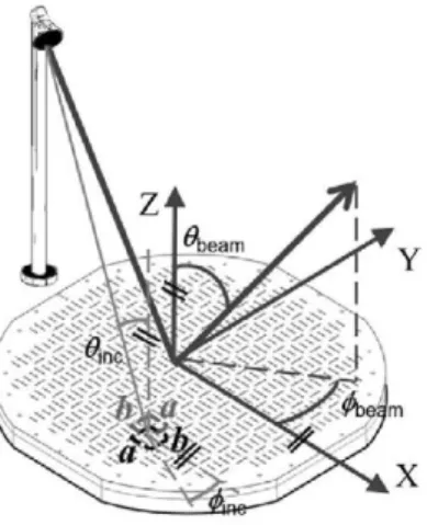
A reflectarray antenna consists of a planar array of reflective elements illuminated by a feed (see Fig. 1), where the phase-shift introduced by each element is pre-adjusted to appropri-ately shape the beam [1]. Although narrow bandwidth is a severe limitation of reflectarray antennas, significant efforts have been done in the last few years to enlarge the bandwidth of these antennas. Different broadband reflectarray elements have been proposed, including stacked patches of variable size [2], patches aperture-coupled to delay lines [3] and multi-resonant coplanar elements [4], [5]. In [6] a broadband element consisting of two orthogonal sets of four parallel dipoles is introduced, which makes it possible to design a dual polarization transmit-receive reflectarray antenna. Although the element proposed in [6] also provides low levels of cross-polar radiation, these levels are in the limit of the stringent requirements that are needed in satellite antennas [6], [7]. Low cross-polar reflectarray elements have already been reported [8], [9], but these elements do not provide enough bandwidth to design transmit-receive reflectarray antennas.
In this work, we propose a cross-polar reduction technique for the transmit-receive reflectarray antennas designed in [6]. The technique makes use of small rotations of the dipoles of each element in order to minimize the cross-polar compo-nents of the fields reflected by that element [10], [11]. The
Fig. 1. Reflectarray antenna made of the elements with two orthogonal sets of dipoles that is shown in Fig. 6 of [6].
computation of those reflected fields is carried out under the local periodicity assumption [1] by means of a home-made software. The software is based on the Method of Moments in Spectral Domain (MoM-SD) [12] with multilayered Green's functions [13]. The entire domain basis functions used to model the current density on the dipoles are fitted to the geometry of the rotated dipoles, and their Fourier transforms are computed as shown in [14]. In order to validate the cross-polar reduction technique, the results obtained for a reflectarray antenna after application of the technique are compared with full-wave results obtained for the antenna with CST®, and good agreement is found. Also, the technique is used for the reduction of the cross-polarization in the the transmit-receive reflectarray antenna designed in [6].
II. DESCRIPTION OF THE CROSS-POLAR REDUCTION TECHNIQUE AT ONE SINGLE FREQUENCY
reflected phase in each polarization. Let us assume the wave impinging on one of the elements of the antenna has an incidence direction given by the spherical coordinate angles 0inc and 4>inc as shown in Fig. 1. In the absence of grating
lobes (i.e., if the dimensions of the unit cell, a and 6, fulfill the conditions a < A0/ (1 + sen(9inc) and b < A0/ (1 + sen(9inc), where A0 is the free space wavelength), only the reflected wave propagating in the specular direction with wavenumber vector kref = -sené>inccos</>incx - sené>incsen</>incy + cosé>incz will contribute to the radiated fields. Let Eref, X-pol = ^e f , X-polx +
ref,X-pol ref,X-pol
Ey, X - p oy + E z ,- p oz be the complex amplitude of the electric field reflected by the element in the specular direction when the electric field of the horn is polarized in the X - Z plane (see Fig. 1), and let E ref,Y-pol = Ex'Y-pol± + Ey 'Y-poly + Ez'Y-pol z
be the complex amplitude of the electric field reflected by the element in the specular direction when the electric field of the horn is polarized in the y-direction (see Fig. 1). Both Eref,X-pol and Eref,Y-pol can be approximately computed by using the local periodicity assumption, i. e., by assuming that the element is located in a periodic environment. In this work, the computation of Eref, X-pol and Eref,Y-pol has been carried out by means of the MoM-SD [12] based on multilayered Green’s functions [13]. Entire domain basis functions that account for edge singularities have been used to model the current on the dipoles. Since in this work the dipoles are rotated for cross-polarization reduction, the transformations proposed in [14] are applied to the basis functions and to their Fourier transforms so that the basis functions fit the geometry of the rotated dipoles. Once the complex amplitudes of the reflected electric fields in the specular direction Eref, X/Y-pol are known, the complex amplitudes of the corresponding reflected magnetic fields in the specular direction will be given by
jrref,X/Y-pol _ rrref,X/Y-pol ~ , rrref,X/Y-pol - , 771
x y J1
ref,X/Y-pol
1
Zo 1 Z
k x E ref, X/Y-pol
re
( £z f, X/Y-pol sen<9incsen</>inc + £ref, X/Y-pol cos 0inc ) x
+ (£ref, X/Y-polsen<9inc cos </>inc + £x ref , X/Y-pol cos 0inc y
- (£r e f , X/Y-polsen<9inc cos </>inc - £r e f , X/Y-polsen(9incsen</>inc ) z ] (1)
where Z0 is the free space impedance.
When the values of Eref, X/Y-pol and Hr e f , X/Y-pol are known
for each specific element, the equivalent currents Je s =
z x Href, X/Y-pol and Jm s = -z x Eref, X/Y-pol can be computed in that element, and the radiated fields can be computed in terms of the equivalent currents in all the elements of the antenna as explained in [15]. It turns out that the equivalent currents are computed in terms of the complex amplitudes of the tangential reflected electric and magnetic fields on each el-ement of the reflectarray, i.e., in terms of E ref,X/Y-pol
ref,X/Y-pol H
reflected fields E
pref,X/Y-pol ^ref,X/Y-pol T h i s means t h a t t h e c o m p o n e n t s of t h e
ref,X-pol
y and H ref,X-pol will contribute to
cross-polar radiation fields when the reflectarray is illuminated by a feed horn polarized in the X - Z plane. And that in case
the reflectarray is illuminated by a feed horn polarized in the y-direction, the components of the reflected fields E ref,Y-pol
a n d i i
ref,Y-pol will contribute to cross-polar radiation fields.These cross-polar components of the reflected fields (i.e., E ref , X-pol Hx**°, Ex'^°l and ify'Y-pol ) can be reduced by
means of small rotations of the two sets of parallel dipoles in each reflectarray element. Let the two rotation angles be o.X and aY, as defined in Fig. 2. Note the rotations of the two sets of dipoles are made around axes which are orthogonal to the plane containing Fig. 2, and pass through the points of coordinates (xelem = xX-Polyelem = yX-Pol) and (xelem = XY-PohJ/elem = S/Y-Pol) in Fig. 2. The rotation angles will be positive if the rotations are counterclockwise. Otherwise, the rotation angles are negative.
Fig. 2. Reflectarray element defined in [6, figure 6] with rotated dipoles.
In order to minimize the cross-polar contributions of the reflected electric and magnetic fields in each element of a reflectarray operating at one single frequency, we define the following cost function:
f(a
X,a
Y)
£<X-pol
^Y-pol
E ref,pol-X (aX, aY) ? + \Z0Hx ol-X (aX, «Y) ?
\E ref,pol-Y Ox (aX,aY)\2 + \Z0Hr e0fvol-Y (aX,aY)\2
+
(2)
where CX-pol and CY-pol are constant coefficients. The rotation
angles aX and aY will be optimized in order to minimize
the cost function f(aX,aY) defined in (2). The constant
coefficients CX-pol and CY-pol can be adjusted to give priority to the minimization of the cross-polarization in either the X-polarization (feed horn polarized in the X - Z plane) or the Y-polarization (feed horn polarized in the y-direction). In this work, the minimization will be carried out by means of Fletcher-Powell algorithm [16]. We would like to point out that the minimization of the function f(aX,aY) is carried
analysis of many small electromagnetic problems dealing with just one unit cell). Since the element rotations should minimally distort the copolar radiation pattern of the antenna without rotations, the rotation angles will be restricted to vary in the range -6° < aX, aY < +6°.
I I I . VALIDATION OF THE CROSS-POLAR REDUCTION TECHNIQUE AT ONE SINGLE FREQUENCY
In order to validate the cross-polar reduction technique proposed in the previous section, we have designed a square reflectarray antenna of size 240 x 240 mm at 11.95 GHz. The reflectarray is designed to radiate a focused beam in the direction 0beam = 16.9° and ^eam = 0° (0beam and </>beam are
defined in the Fig. 1). The reflectarray consists of 400 elements arranged in a 20 x 20 grid with cell size a = b = 12 mm. The reflectarray elements will be those shown in Fig. 2, and the substrate parameters and geometrical relations employed will be those used in Section II.C of [6] in the case where aX = aY = 0°. The reflectarray is assumed to be illuminated by a pyramidal horn, whose phase center is assumed to be located at the point of coordinates X = -85.3 mm, Y = 0 mm and Z = 281 mm with respect to a system of coordinates with origin at the center of the reflectarray (see Fig. 1). This feed horn provides an illumination level at the reflectarray edges of 11 dB below the maximum. A full wave analysis of the horn has been carried out by means CST® in order to obtain the electric and magnetic fields at the aperture of the horn. These fields have been used to compute the incident field on each element of the reflectarray by using the angular spectrum of plane waves [17] (which means that the near-field of the horn has been used to rigorously compute the incident field on each reflectarray cell)
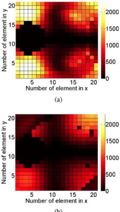
The reflectarray antenna is first designed in the case where the rotation angles aX and aY of Fig. 2 are zero in all the elements of the reflectarray. Fig. 3(a) shows the values obtained in that case for the cost function defined in (2). Then, the angles aX and aY are optimized in all the reflectarray elements for which 0inc > 10° (the elements for which 0inc < 10°
have not been taken into account in the optimization process because their contribution to cross-polarization is negligible). The results obtained for the cost function after optimization are shown in Fig. 3(b). Note that the cost function is signif icantly reduced in the optimization process. Fig. 4 shows the values obtained for the rotations angles, aX and aY, in each reflectarray element after the optimization process.
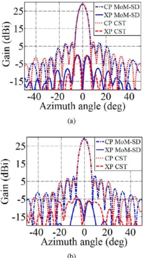
The radiation patterns obtained for the reflectarray antenna before the optimization process and after the optimization process are shown in Fig. 5. The results have been obtained with both our home-made software and commercial software CST®. In the case of our home-made software, the radiation fields are efficiently computed in terms of a F F T of the equivalent currents on the aperture of the reflectarray [15], and the equivalent currents are computed via MoM-SD while assuming local periodicity. In the case of CST®, a full-wave simulation of the whole antenna is carried out without
(a)
(b)
Fig. 3. Values of the function defined in (2) in each reflectarray element. (a) Prior to optimization process. (b) After optimization process.
(a)
(b)
using local periodicity. Whereas the analysis of the whole reflectarray antenna took around 8 hours in a computer with 2 Intel Xeon Processors (6 cores per processor), 2.1 GHz of clock frequency and 128 GBytes of RAM memory, our home-made software only took 27 seconds in a computer with 1 Intel i5 processor (2 cores per processor), 2.6 GHz of clock frequency and 8 GBytes of RAM memory. The enormous amount of CPU time required by CST® in a very powerful computer prevented us from analyzing an antenna with a larger number of elements. Note that the agreement between our home-mode software and CST® is acceptable, and it is excellent in the angular region of the main lobe. Figs. 5(a) and (b) show that the rotation of the dipoles makes it possible a reduction of roughly 5 dB in the level of the cross-polar radiation for X-polarization, which ensures a level of cross-polar discrimination of 34 dB for the antenna with rotated dipoles. Similar results have been obtained for Y-polarization.
(a)
(b)
Fig. 5. Simulated radiation patterns in azimuth plane for the focused beam reflectarray antenna in the X-polarization. (a) Prior to optimization process. (b) After optimization process. Co-polar (CP) and cross-polar (XP) components are shown.
IV. CROSS-POLAR REDUCTION FOR THE TRANSMIT-RECEIVE REFLECTARRAY ANTENNA
Let us consider the transmit-receive (Tx-Rx) dual-polarization reflectarray antenna designed in [6]. This antenna generates a pencil beam in the direction é>beam = 16.9° and ^beam = 0° at the frequency bands 11.3 - 12.6 GHz (Tx) and 13.75-14.25 GHz (Rx) for both polarizations. The reflectarray is illuminated by a corrugated circular horn with very low
levels of cross-polarization. The phase center of the corrugated horn is assumed to be located at the point of coordinates X = -193 mm, Y = 0 mm and Z = 635 mm (see Fig. 1). The radiation pattern of the corrugated horn has been modeled as cos9(0), where q varies with frequency. The feed illuminates the edges of the reflectarray with a taper of -10 dB for Tx-band and -13 dB for Rx-Tx-band.
In order to minimize the cross-polar contributions of the reflected electric and magnetic fields in each element of the reflectarray operating at both frequency bands Tx and Rx, we define the cost function /Tx-Rx (aX, o.Y) as
C l [ |E ref,pol-X (/0, aX, aY ) | 2 + |E ref,pol-Y (/0, aX, aY ) | 2 i=Tx,Rx
+ |Z0H ref,pol-X ( /0 , «X, « Y ) | 2 + |Z0fr y ef,pol-Y ( f0, «X, « Y ) | 2] (3)
where /0Tx = 11.95 GHz and /0 R x = 14.00 GHz. The constant coefficients CTx and CRx can be adjusted to give priority to the minimization of the cross-polarization in either the Tx-band or the Rx-Tx-band. As in the case treated in Sections II and III, the rotation angles aX and aY are optimized in order to
minimize the function /T x R x (aX, aY). To create a minimum
distortion in the copolar radiation patterns obtained before dipoles rotation, the rotation angles are restricted to vary in the range -6° ≤ aX, aY ≤ +6°.
(a)
(b)
(a)
(b)
Fig. 7. Simulated radiation patterns in azimuth plane for the Tx-Rx reflectarray antenna with rotated dipoles in the Rx-band. (a) Results for X-polarization. (b) Results for Y-X-polarization.
Figs. 6 and 7 show the values of the co-polar and cross-polar radiations patterns generated by the focused beam Tx-Rx reflectarray antenna designed in [6] after the optimization process in which the dipoles have been rotated to minimize the cost function defined in (3). By comparison with the results plotted in [6], one can check that the level of cross-polar radiation has been reduced by roughly 10 dB in the case of X-polarization, and roughly 5 dB in the case of Y-polarization. As a consequence of this, the minimum level of cross-polar discrimination is 40 dB for the X-polarization (in the Tx band), and 35 dB for the Y-polarization (in the Rx band).
V. CONCLUSION
A cross-polar reduction technique has been proposed for reflectarray antennas. This cross-polar reduction technique is based on the rotation of the reflectarray elements. In particular, the rotation angles that minimize the cross-polar components of the reflected electric and magnetic fields in each element are sequentially determined via an optimization process. The reflected fields in the different elements are computed by means of a home-made MoM software while assuming local periodicity. In order to validate the cross-polar reduction technique, the results obtained for an optimized antenna at one single frequency are compared with results obtained by means of CST®, and excellent agreement is found. The cross-polar reduction technique has also been applied to a Tx-Rx dual-polarization reflectarray antenna operating at two frequency
bands. The results obtained indicate a minimum reduction of 10 dB in the cross-polar radiation for one polarization and a minimum reduction of 5 dB in the cross-polar radiation for the orthogonal polarization, these reductions being obtained at both the Tx and Rx frequency bands.
ACKNOWLEDGMENT
This work has been supported in part by the Spanish Ministry of Science and Innovation under Project C I C Y T TEC2013-43345-P, in part by European Space Agency un der E S T E C Contract 4000106334, and in part by “Junta de Andaluc´ıa under Project P12-TIC-1435.
REFERENCES
[I] J . Huang, J . A . Encinar, Reflectarray antennas, Piscataway, NJ/New York: I E E E Press/Wiley, 2008.
[2] J . A . Encinar, “Design of two-layer printed reflectarrays using patches of variable size,” IEEE Trans. Antennas Propagat., vol. 49, pp. 1403–1410, Oct. 2001.
[3] E . Carrasco, M . Barba and J . A . Encinar,“Aperture coupled reflectarray element with wide range of phase delay,” Electron. Lett., vol. 42, No.12, pp. 667-668, Jun. 2006.
[4] M . R . Chaharmir, J . Shaker, and H . Legay, “Broadband design of a single layer reflectarray using multi cross loop elements”, IEEE Trans. Antennas
Propagat., Vol. 57, pp. 3363-3366, Oct. 2009.
[5] L . Moustafa, R . Gillard, F. Peris, R . Loison, H . Legay and E . Girard, “The Phoenix cell: a new reflectarray cell with large bandwidth and rebirth capabilities,” IEEE Antennas Wirel. Propag. Lett., Vol. 10, pp. 71-74, 2011.
[6] R . Florencio, J . A . Encinar, R . R . Boix, V. Losada and G . Toso , “Reflectarray antennas for dual polarization and broadband telecom satellite applications,” IEEE Trans. Antennas Propag., vol. 63, No. 4, pp. 1234-1246, Apr. 2015.
[7] J . A . Encinar, M . Arrebola, L . F . de la Fuente, and G . Toso, “A transmit-receive reflectarray antenna for direct broadcast satellite applications,”
IEEE Trans. Antennas Propag., vol. 59, pp. 3255-3264, Sep. 2011.
[8] H . Hasani, M . Kamyab and A . Mirkamali, “Low cross-polarization reflectarray antenna,” IEEE Trans. Antennas Propag., vol. 59, No. 5 pp. 1752-1756, May. 2011.
[9] D . Bresciani, H . Legay, G . Caille and E . Labiole, “Reflector array antenna with cross-polarization compensation and method for producing such an antenna,” U . S . Patent 2013/0099990 A 1 , Apr. 2013.
[10] J . A . Encinar, M . Arrebola, Mentzel, G . Toso and C . Mangenot “Dual polarization reflectarray antenna with improved cross polarization prop erties,” European Patent E P 2337152 A 1 , 2011.
[ I I ] R . Florencio, J . A . Encinar, R . Boix, G . Toso, “Wideband reflectarray antenna for dual polarization applications,” European Space Agency Patent filed on April 30 2014 (application number PCT/IB2014/002265). [12] R . Mittra, C . H . Chan, and T . Cwik, “Techniques for analyzing frequency selective surfaces-A review”, Proc. IEEE. vol. 76, no. 12, pp. 1593-1615, Dec. 1988.
[13] F . Mesa, R . Marque´s, and M . Horno, “A general algorithm for comput ing the bidimensional spectral Green’s dyads in multilayered complex bianisotropic media: the equivalent boundary method,” IEEE Trans.
Microwave Theory Tech., vol. 39, pp. 1640–1649, Sept. 1991.
[14] C . K . Aanandan, Pierluigi Debernardi, Renato Orta, Riccardo Tascone, and Daniele Trinchero, “Problem-Matched Basis Functions for Moment Method Analysis An Application to Reflection Gratings”, IEEE Transac
tions on Antennas and Propagation, vol. 48, no. 1, january 2000.
[15] M . Zhou, S . B . Sorensen, O . S . Kim, E . Jorgensen, P. Meincke, O . S . Kim and O . Breinbjerg, “An accurate technique for calculation of radiation from printed reflectarrays,” IEEE Trans. Antennas Propagat., vol. 10, pp. 1081–1084, Oct. 2011.
[16] W . H . Press, S . A . Teukolsky, W . T. Vetterling, B . P. Flannery, Numerical
Recipes in FORTRAN –The Art of Scientific Computing–, Cambridge
University Press, 2nd Edition, 1992.
![Fig. 2. Reflectarray element defined in [6, figure 6] with rotated dipoles.](https://thumb-us.123doks.com/thumbv2/123dok_es/6855697.838187/2.892.554.729.360.560/fig-reflectarray-element-defined-figure-rotated-dipoles.webp)