Simulation of the GPTAD applied to the removal
of blood clots that arise during Peripheral
Vascular Disease
G. Romero, I. Higuera, M.L. Martinez ETSI Engineering, Universidad Politécnica de Madrid
Madrid, Spain
e-mail: gregorio.romero@upm.es, irene.higuera@upm.es, luisa.mtzmuneta@upm.es
G. Pearce, N.D. Perkinson Wolverhampton University Wolverhapton, United Kingdom e-mail: gillpearce@googlemail.com,
neil@perkinson.org.uk
Abstract— A number of Thrombectomy devices using a variety of methods have now been developed to facilitate clot removal. We present research involving one such experimental device recently developed in the UK, called a 'GP' Thrombus-Aspiration-Device (GPTAD). This device has the potential to bring about the extraction of a thrombus. Although the device is at a relatively early stage of development, the results look encouraging. We present an analysis of modelling this device using modelling techniques. Such modelling appears to be highly effective in simulating the device under a variety of conditions with a view to assisting in the optimisation of the GPTAD. The aim of this simulation model is to obtain the minimum pressure necessary to extract the clot and to verify that, both the pressure and the time required to complete the clot extraction are reasonable for use in clinical situations, and are consistent with any experimentally obtained data.
Keywords- Biomedical engineering, Thrombectomy Device, Simulation techniques.
I. INTRODUCTION
Peripheral vascular disease (PVD) affects some 12 million people in the United States alone [1]. The prevalence of peripheral vascular disease in people aged over 55 years in the UK is 10%-25% -however- this figure rises it with age. Although 70%-80% of affected patients are asymptomatic, only a relatively small number of these ever require revascularisation procedures or amputation [2]. Chiefly PVD is caused by atherosclerosis [3], and it is believed by some that PVD may be underdiagnosed [4]. Major risk factors for peripheral arterial disease include cigarette smoking, diabetes mellitus, hypertension, and hyperlipidemia.
The patient often experiences symptoms that include colour changes to the lower limbs and feet, intermittent claudication (pain commonly in the calf, thigh or buttock on walking a relatively short distance), and a burning sensation in the legs and feet at night in bed that is commonly relieved by hanging the legs over the side of the. It is also characterised by an abnormal ankle brachial index measurement [5]. Measurements of so-called ankle brachial pressure index (ABPI/ABI) using Doppler ultrasonography
may be used in the diagnosis of peripheral vascular disease, in conjunction with a physical examination of the patient. ABPI/ABI is a measure of the decrease in blood pressure in the arteries supplying the legs. A fall in ABPI (less than 0,9) is consistent with PVD. Values of ABPI below 0,8 indicate moderate disease and below 0,5 severe disease. However, it is possible for other conditions to give false readings e.g. conditions which stiffen the vessel walls (such as calcifications in the vessel wall that occur in e.g. chronic diabetes). Other tests that may be used include magnetic resonance angiography. Cigarette smoking, diabetes mellitus, hypertension, hyperlipidemia, age greater than 40 years, all lead to an increased risk of developing PVD.
Smoking is the most important risk factor and perhaps carries the greatest risk of developing PVD [6], and cessation of smoking appears to reduce the progression of PVD [7],
II. TREATMENTS FOR PVD
Treatments include life style modification, exercise training, and drug therapy, angioplasty, bypass graft, and amputation [3].
Drug therapies for peripheral arterial disease include aspirin (with or without dipyridamole), and clopidogrel. Good glycaemic control appears to decrease the incidence of intermittent claudication or critical limb ischemia [8].
vessel. The latter may be undertaken using either the saphenous vein, or an artificial materials. Sympathectomy may be used to denervate nerves that cause vasoconstriction of arteries, thus bringing about vasodilation of the vessel. Amputation may be performed as a last resort to prevent the spread of infection in cases where gangarene has ensued.
A blood clot may sometimes develop at the site of the atheromatous plaque in the affected limb. In such instances attempts can be made to dissolve the clot using a thrombolytic agent such as tPA or heparin. Removal of the clot may also be undertaken by an embolectomy catheter.
III. GPATD STRUCTURE
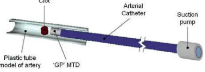
Recently a thrombus aspiration device called the GPTAD has been invented by Pearce and Perkinson [10][11]. In the sections below we have used Bond Graph modelling to model the removal of such a blood clot in the lower limb. The aim of such modelling is to show how bond graph modelling may possibly be used to optimsize the GPTAD as a device (figure 1) for a potential treatment for the removal of blood clots that arise during PVD.
The GPTAD device assembly involves using a vacuum pump (that provides the suction pressure for removal of the clot), joined to a very long catheter (-100 cm long and ~1,5-2,0 mm in diameter); the 'GP' device is located at the end of this catheter (same diameter and a length of 20 mm). This GPTAD is introduced into the popliteal artery via a transfemoral approach to the lower limb such that the GPTAD is positioned in close proximity to the occluding blood clot, at a distance of approximately 3 mm from it. Then the suction begins until the clot is extracted. The clot crosses the 3 mm that separates it from the GPTAD and when clot capture occurs the device is then removed from the body.
Clot
Arterial
Catheter Suction
Plastic tube \ model of artery 'GP' MTD
Figure 1. Schematic view of the GPTAD
It is currently being developed as a potential thrombus aspiration device through a series of in-vitro studies. This device has the potential to be used in relatively small arteries. It has no moving parts and therefore should reduce the risk of breakage in a vessel. Since it does not touch the clot itself it should also reduce the risk of clot disruption and downstream embolisation. Thrombectomy is achieved by aspiration through a catheter in which the 'GPTAD' device is embedded. The internal surface has been mathematically optimized. It is also potentially associated with low forces at the periphery of the device which may therefore reduce the risk of arterial collapse during aspiration of the clot [12].
IV. MODELLING THE GPTAD DEVICE
The objective of this study is to introduce a model that can be used investigate and assist in the final design of the GPTASD. We investigate the potential performance of the GPTAD device under different conditions of blood flow, size of blood clot, in a given vessel. The method chosen for the representation and simulation of the GPTAD in this instance is the Bond Graph technique [13]. Some models have been modeled by using this technique [14][15] and its choice is based on the fact that this technique allows assimilating the model to an electric circuit made up of resistances, capacitances and inductances. Therefore, it is possible to obtain the results in a simple way by evaluating flows and efforts that join and connect the components of the model. To obtain the simulation of the model, Bondin © software will be used [16]. This program allows obtaining the evolution of the characteristic parameters of the model as well as letting them be compared.
To generate the correct model, it was necessary to analyze the resistances that appear when fluid and blood clot flow into the catheter, the inertances due to mass of fluid, and finally the compressibility that the blood and artery are subjected to [17].
A. Resistances
Linear load loss is due to the friction between the liquid particles and the artery walls. To simplify, only linear load losses are taken into account. If we suppose that the artery is composed of successive horizontal pipes of constant cross section in each section, the load loss is reduced to a pressure loss as the fluid advances along the artery, the loss being progressive and proportional to the length of the artery. If we assume that the blood flow is laminar due to the Reynolds number being approximately 1.000 (Re<2.200), the equation that governs the behaviour in the catheter can be determined by the following expression:
where 'n' is the dynamic viscosity of the blood flow, 'L' the length of the catheter section and 'D' its diameter.
Some studies show that in diseased arteries viscosity bloodstream varies, increasing its value but for this first approximation we used a normal value of 0,0035 Pas.
Later in the model, the 'GPTAD' device (see figure 1) is positioned near the clot. The resistance of the blood flow can be represented by the same eq. (1) with the corresponding values.
where ' p ' is the blood density (1.060 kg/m3), 'Q' is the flow
which circulates in the section between the end of the 'GP' device and the artery, and the diameter 'D' is the mean value between the cylinder and the artery.
In addition, the load loss coefficient '£' is a dimensionless parameter that quantifies the loss produced and depends on the geometry of the deflecting nozzle; since this is a narrowing, this value is 0,43-0,45.
Finally, the friction between the clot and the arterial wall creates another resistance factor. The value of this parameter must be variable depending on whether the clot has begun its movement (dynamic friction) or before it has begun to move (static friction) during the clot extraction procedure. When the clot begins to move the friction decreases considerably. This value is obtained from the Stokes equation and can be given a value of 2,5 TO"6 Ns/m for the static friction and an
order of magnitude lower than for the dynamic friction. The transition between both values marks the beginning or end of the clot movement.
B. Inertances
The flow inertia to be overcome in the movement from clot to pump must be taken into account and it can be modelled with the flow and the section. Considering a section with circular geometry, we can assume the blood inertance with the following expression:
where ' p ' is the blood density, 'L' the length of the same artery section done when resistances were studied, and 'D' its diameter. To obtain correct values, it's necessary to apply the length and sections depending on different areas of the (catheter, the GP device or the space between the GPTAD and clot).
In addition to the previous inertance inserted, the model must have an inertance that represents the mass of the clot (0,6-5,5 gr).
C. Compresibilities
To complete the model, the blood compressibility must be included with the previous values in the model. In fact, it acts as a compliance producing a decrease in volume when the pressure required for compression is increased. This behaviour is dependent on the Bulk's blood coefficient (B, with a value 2,2T09 N/m) and section of the artery. If we
assume a circular geometry, it can be defined as a capacitance of K value:
where 'L' is the total length of the catheter, GPTAD and GP-clot distance.
In addition, it is necessary to insert the compressibility of the length of artery that appears between the GP device and the clot, in line with its Young's modulus:
where 'E' is its Young's modulus (2,8T09 N/m), 'h' is the
thickness of the artery (0,1 mm), 'V0' is the artery initial
volume and 'r0' is the artery initial radius.
In addition to resistance, inertance and compressibility, the pump creates the necessary pressure to carry out the extraction, and is positioned at the other end of the vatheter that does not contain the GPTAD. In the model, it is represented by a variable pressure source whose value will increase from zero to a non-determined value suitable for carrying out the operation of clot removal and will be obtained from the optimization of the developed model. The time taken to reach the maximum value of pressure has been obtained from experiment and is about 2-3 sec, after which time the pressure provided by the pump remains constant.
In order to calculate the effect of the entire catheter in this model, (due to the length), it was partitioned in identical sections (ten sections) and was represented by ten sub-models that include the previous described parameters.
Once all this was defined in the model, it was necessary to change from the hydraulics to mechanics domain before considering the clot element, to be able to evaluate the clot movement and effort involved in clot extraction taking into account the physical friction between the clot and the artery.
This domain change is carried out by a Transformer (TF) element. To calculate the value of the coefficient defining this element, the change in the definition of the flow before and after this element is evaluated. Before the transformer, the flow is in the hydraulics domain, while after, it is in the mechanics domain. The coefficient was determined by evaluating the required change between both domains.
r =
/A=K-R
2(
fi)
where 'R' is the artery radius.
Finally, in figure 2 it's possible see the full model of the complete GPTAD, in which we can see the order of the different elements. To formulate the corresponding equations from the different described phenomena, it was necessary to assume that the flow after and before resistances and inertances are the same; nevertheless, with this assumption in respect of after and before compliances the pressures are similar.
Mechanic domain
A
Clot - T F
,\¿-
¥-Artery
i^-Blood
\\¿-Hydraulic domain
Deflecting
nozzle GPTAD
ÍK-Arterial Catheter
Suction pump
Figure 2. Full model of the GPTAD.
The main objective of the development of this simulation model will be to obtain the minimum pressure required to perform the extraction and to check that this pressure together with the time required to complete the operation are reasonable are within acceptable clinical boundaries for eventual potential use of the GPTAD on a patient, and are similar to experimentally obtained data. These studies and confirmations will allow optimization of the device to assist in possible future use of this device in patients with thrombosis.
V. APPLICATION TO THE POPLITEAL ARTERY. By using the previous phenomena, it has been simulated the extraction of a blood clot from the popliteal posterior artery. For the present study it has been considered a diameter of 1,5 mm for the catheter and the 'GP' and, for the artery a diameter of 4mm.
Simulations of this model have been undertaken for several lengths of the clot, from 10 mm to 90 mm. To simulate each length, we considered that the clot mass is dependent from on geometry (volume). To simplify the problem, the geometry that has been considered assumed that the clot and the plaque together are a cylinder each occupying 50 % of the diameter of the popliteal artery, as can be seen in figure 3.
Removal Clot
Figure 3. Schematic view of plaque and removal clot in PVD.
In this model, the clot is a half cylindrically-shaped element of [1-9] cm in length, and of a mass that falls between [0,6-5,5] gram. Due to the difference in diameter between the clot and artery-plaque (a constriction of flow in the artery leads to the formation of a clot), the clot becomes attached to the artery wall by a force of adhesion, that needs to be overcome in order to facilitate clot movement for removal. In addition, the relative movement between the clot and the artery presents static and dynamic friction, which needs to be taken into account. If a correct approximation to reality is to be achieved all these phenomena, as well as the circumstances restricting clot movement, need to be considered.
The suction pressure that generates the pump actuates in both elements: the clot and the plaque. To obtain the displacement of the clot we have assumed that its surface is half of the artery's section. Moreover, when different masses are being considered, the surface in contact with the artery wall and the plaque, changes. As already stated, the phenomenon preventing clot movement is the difference in diameter between the clot and the artery-plaque where it is located. We have assumed that the force of attachment of the clot to the artery wall is -0,0 IN, based on a simple calculation involving density, volume and pressure, and assuming a spherical clot (in the absence of any experimental data or values available in the literature). Clot movement therefore begins when this force is equal to 0,01 N. In our model we have assumed that this force of 0,0 IN applies equally well to any other clot geometry, and it has been included as a superficial stress parameter. The superficial stress can be calculated as the force that is necessary to overcome movement divided by the length in contact with the wall artery and the plaque. This line of contact is in the periphery of the clot, between artery wall and plaque, in figure 4.
Superficial tension
Catheter
Figure 4. Suction force over clot and superficial tension.
K = y = F II (7)
As stated above, the clot is between [1-9] cm long, which means it can be broken down into the union of several spheres, all with the same constant. Since over the whole surface of the clot there are forces of adhesion, to obtain a correct approximation it is necessary to consider the existence of a sphere for every 0,1 mm. This means that between 100 and 900 spheres would need to be included in the model. On the other hand, all the spheres must be located in parallel to obtain the resultant adhesive force, and since all the individual compliances are equal, the number of spheres depends on the length of the clot, i.e., the equivalent compliance for a 5 cm clot (500 spheres) can be obtained from the form appearing in the following expression:
K„ F/l 0,525762
500 0,001052 N/m (8)
To know when the force has been obtained in this equivalent compliance and, therefore, when the clot movement will begin, it is essential to calculate the displacement of the compliance when it is subjected to 0,01 N through a typical compliance equation. Therefore, only when the compliance undergoes this displacement should the clot be able to move; less than this value would mean that the clot could not move. The clot has to traverse a displacement of 3 mm until it reaches to the end of the GPTAD. The time to complete this displacement with different pressures is the time that results from the modelling.
VI. RESULTS
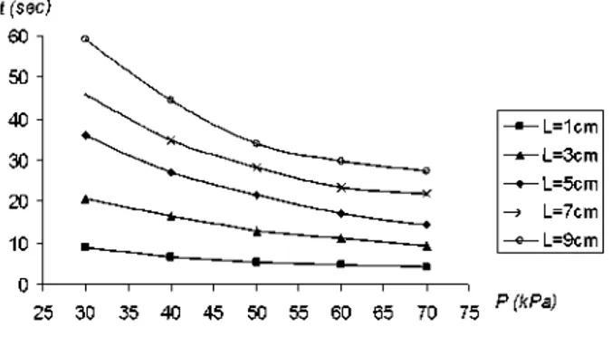
Figure 5 shows the results for the modeling undertaken. Different lengths of clot were modelled (1 cm, 3 cm, 5 cm, 7 cm and 9 cm) at different pressures (30 kPa, 40 kPa, 50 kPa, 60 kPa and 70 kPa).
In figure 5 results are shown, for each length of clot, together with the time when the clot begins to move until and it reaches the end of the 'GP' device.
f (sec) 60
50
40
30
20
-10
-L=1cm - L=3cm - L=5cm L=7cm - L=9cm
25 30 35 40 45 50 55 60 65 70 75 P (kPa)
Figure 5. Time to end of the extraction Vs suction pressure.
In considering the results of the modelling presented in figure 5, it can be seen that clots with a length between 1 cm to 3 cm, need relatively low suction pressures and short times for clot capture. However, clots with a size between
5cm to 9cm show a bigger variation in the time involved with different pressures.
For a clot of length 1cm, the times to complete the displacement are relatively low. So a low pressure could possibly be used to extract such a clot.
For a clot of length 3cm the times taken for extraction are within the range [9-21] seconds. This range seems reasonable and we could conclude that a pressure of ~30 kPa could be enough to remove the clot in ~21 seconds.
For clots of length between 5 cm to 9 cm the results indicate that the times required for removal are higher; for a 5 cm clot this range is [14-36] seconds. A pressure of 50 kPa appears to remove the clot in a time of-21,5 seconds.
We could therefore speculate that for a clot of length 7 cm, a pressure of ~50 kPa or ~60 kPa may be required to remove the clot in ~24 seconds or ~28 seconds. However using a lower pressure it is possible to remove the clot, but the times are sharply increased.
Finally for a clot of length 9 cm, the times are within the range [28-60] seconds. We could conclude that 28 seconds seems to be a reasonable time avoiding lengthening the operation of extracting the clot.
The times that are calculated with this model show only the time necessary for the extraction of the clot once the 'GP' is correctly situated. However to obtain the whole time to carry out the operation, it would be necessary to add on the time taken to situate the 'GP' in the artery and the time to take it out of the body.
VII. CONCLUSIONS
The simulation shows that pressures between [30-70] kPa seem to be enough to remove clots of differents sizes in a range within [4-60] seconds. No in-vitro data currently exists for this device in respect of its use in the leg to remove blood clots that arise during peripheral vascular disease, so no comparisons can yet be made between in-vitro measurements using models and our Bond graph modelling.
Moreover, analyzing the resistances in the catheter indicates that an important pressure loss takes place in the catheter joining the pump to the 'GP'. The values obtained could possibly be used to optimize its geometry.
VIII. FUTURE WORKS
Bond Graph mathematical modelling is now being implemented to model and simulate the coronary vessels of the heart. The analysis will involve the GPTAD in proximity to both athromatous plaques and blood clots, in coronary vessels which become blocked in myocardial infarction.
REFERENCES
[1] Ouriel K. Detection of peripheral arterial disease in primary care. JAMA 2001;286:1380-1
[2] Mayo Clinic Proceedings website. http://www.mayoclinicprocee
dings.com/content/83/8/944.full.pdf+html. Last accessed 10th Nov 2008.
[4] Hirsch A.T. et al. 2001. "Peripheral arterial disease detection, awareness, and treatment in primary care". JAMA 2001;286:1317-24 [5] McDermott M.M. et al. 2002. "The ankle brachial index is associated
with leg function and physical activity: the Walking and Leg Circulation Study". Ann Intern Med 2002;136:873-83.
[6] Regensteiner, J.G. and Hiatt, W.R. 2002. "Current medical therapies for patients with peripheral arterial disease: a critical review". Am J Med 2002;112:49-57.
[7] Girolami, B. et al. 1999. "Treatment of intermittent claudication with physical training, smoking cessation, pentoxifylline, or nafronyl: a meta-analysis". Arch Intern Med 1999;159:337-45.
[8] Beckman, J.A. et al. 2002. "Diabetes and atherosclerosis: epidemiology, pathophysiology, and management.". JAMA 2002;287:2570-81.
[9] Adler A.I. et al. 2002. "UKPDS 59: hyperglycemia and other potentially modifiable risk factors for peripheral vascular disease in type 2 diabetes". Diabetes Care 2002;25:894-9.
[10] Pearce G, and Perkinson ND, "Biomechanical Probe". 2006; International Patent Corporate Treatise (WO2006120464) published 2006-11-16; European patent (EP1893195 (A2)) published 2008-03-05; Japanese patent (JP2008639924 (T)) Published 2008-11-20; Chinese patent (CN101208049 (A)) published 2008-06-25.
[11] Pearce, G. et al. 2008. "The design, optimisation, and testing of a new mechanical clot retrieval device for use in vascular surgery". International Journal of Engineering Simulation. Vol. 9, No. 2, pp. 10-26.
[12] Pearce, G. et al. 2009. "An Investigation of fluid flow through a modified design for the 'GP' device". 11th International Conference on Computer Modelling and Simulation, pp. 191-195. Cambridge, UK.
[13] Karnopp, D.C. et al. 1990. "System Dynamics: A Unified Approach". John Wiley & Sons, Inc., Second edition.
[14] Zadpoor, A.A. et al. 2005. "A bond graph approach to the modelling of fluid-solid interaction in cardiovascular system's pulsatile flow". 27th Annual International Conference of the IEEE in Medicine and Biology Society (EMBC05), Shanghai, China.
[15] Tabatabai, G.F. et al. 2005. "Spatiotemporal wavefront propagation in 3D geometric excitable heart tissue utilizing Bond Graph modelling technique". 2005 International Conference on Bond Graph Modelling and Simulation (ICBGM'2005), New Orleans, USA.
[16] Romero, G. et al. 2009. "BONDIN: a new engineering simulation software for ODE and DAE systems with symbolic notation based on the Bond Graph technique". 8th WSEAS Int. Conf. on Software engineering, parallel and distributed systems, pp. 90-97. Cambridge, UK.
![Figure 3. Schematic view of plaque and removal clot in PVD. In this model, the clot is a half cylindrically-shaped element of [1-9] cm in length, and of a mass that falls between [0,6-5,5] gram](https://thumb-us.123doks.com/thumbv2/123dok_es/6826876.835602/4.918.492.814.611.808/figure-schematic-plaque-removal-cylindrically-shaped-element-length.webp)