DIPLOMADO DE PROFUNDIZACIÓN CISCO
(DISEÑO E IMPLEMENTACIÓN DE SOLUCIONES INTEGRADAS LAN / WAN
EVALUACIÓN – PRUEBA DE HABILIDADES PRÁCTICAS CCNA
GRUPO 102059_60
CARLOS ADRIAN PACHECO PINILLA
79981831
TUTOR
EFRAIN ALEJANDRO PEREZ
UNIVERSIDAD NACIONAL ABIERTA Y A DISTANCIA
ESCUELA DE CIENCIAS BASICAS Y TECNOLOGÍAS
CONTENTS
INTRODUCCIÓN ... 3
DESARROLLO DE LA ACTIVIDAD ... 4
Escenario 1
... 4
Escenario 2 ... 16
ARCHIVOS .pkt ... 29
CONCLUSIONES ... 30
INTRODUCCIÓN
El desarrollo de esta actividad de habilidades prácticas pone a prueba nuestros conocimientos adquiridos en el desarrollo del Diplomado de Profundización CCNA, buscando fortalecer las habilidades adquiridas durante este diplomado.
La solución de problemas relacionados con diferentes aspectos del Networking, sólo pueden ser posibles gracias a la comprensión de los conceptos recibidos durante el diplomado.
DESARROLLO DE LA ACTIVIDAD
Escenario 1
Tabla de direccionamiento
El administrador Interfaces Dirección IP Máscara de subred Gateway predeterminado
ISP S0/0/0 200.123.211.1 255.255.255.0 N/D
R1
Se0/0/0 200.123.211.2 255.255.255.0 N/D
Se0/1/0 10.0.0.1 255.255.255.252 N/D
Se0/1/1 10.0.0.5 255.255.255.252 N/D
R2
Fa0/0,100 192.168.20.1 255.255.255.0 N/D
Fa0/0,200 192.168.21.1 255.255.255.0 N/D
Se0/0/0 10.0.0.2 255.255.255.252 N/D
Se0/0/1 10.0.0.9 255.255.255.252 N/D
R3
Fa0/0 192.168.30.1 255.255.255.0 N/D
2001:db8:130::9C0:80F:301 /64 N/D
Se0/0/0 10.0.0.6 255.255.255.252 N/D
Se0/0/1 10.0.0.10 255.255.255.252 N/D
SW2 VLAN 100 N/D N/D N/D
VLAN 200 N/D N/D N/D
SW3 VLAN1 N/D N/D N/D
PC20 NIC DHCP DHCP DHCP
PC21 NIC DHCP DHCP DHCP
PC30 NIC DHCP DHCP DHCP
PC31 NIC DHCP DHCP DHCP
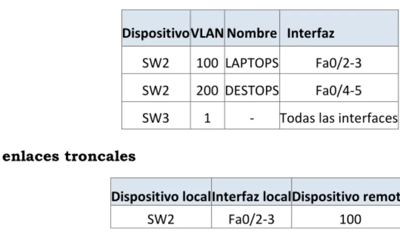
Tabla de asignación de VLAN y de puertos
Dispositivo VLAN Nombre Interfaz
SW2 100 LAPTOPS Fa0/2-3
SW2 200 DESTOPS Fa0/4-5
SW3 1 - Todas las interfaces
Tabla de enlaces troncales
Dispositivo local Interfaz local Dispositivo remoto
SW2 Fa0/2-3 100
Situación
En esta actividad, demostrará y reforzará su capacidad para implementar NAT, servidor de DHCP, RIPV2 y el routing entre VLAN, incluida la configuración de direcciones IP, las VLAN, los enlaces troncales y las subinterfaces. Todas las pruebas de alcance deben realizarse a través de ping únicamente.
Descripción de las actividades
• SW2 VLAN y las asignaciones de puertos de VLAN deben cumplir con la tabla 1.
Switch>en Switch#config t
Enter configuration commands, one per line. End with CNTL/Z. Switch(config)#vlan 100 Switch(config-vlan)#name LAPTOPS
Switch(config-vlan)#vlan 200 Switch(config-vlan)#name DESKTOPS
Switch#config t
Switch(config)#int range fa0/2-3 Switch(config-if-range)#switch Switch(config-if-range)#switchport mode ac
Switch(config-if-range)#switchport mode access
Switch(config-if-range)#swic Switch(config-if-range)#switc Switch(config-if-range)#switchport acc
Switch(config-if-range)#switchport access vlan 100
Switch(config-if-range)#int range fa0/4-5
Switch(config-if-range)#switchport mode access
Switch(config-if-range)#switchport access vlan 200
10
SW3(config)# SW3(config)#vlan 1 SW3(config-vlan)#exit
SW3(config)#int range f0/1-24 SW3(config-if-range)# swit
SW3(config-if-range)# switchport mode access
SW3(config-if-range)#swit SW3(config-if-range)#switchport access vlan 1
• Los puertos de red que no se utilizan se deben deshabilitar.
Switch(config-if-range)#int fa0/1 Switch(config-if)#switchport mode trunk
Switch(config-if)#int range fa0/6-24
Switch(config-if-range)#shut
SW3#config t
• La información de dirección IP R1, R2 y R3 debe cumplir con la tabla 1.
Router>enable
Router#configure terminal Enter configuration commands, one per line. End with CNTL/Z. Router(config)#hostname R1 R1(config)#
R1(config)#int s0/0/0
R1(config-if)#ip address 200.123.211.2 255.255.255.0 R1(config-if)#exit
R1(config)#int s0/1/0
R1(config-if)#ip address 10.0.0.1 255.255.255.252
R1(config-if)#exit R1(config)#int s0/1/1
R1(config-if)#ip address 10.0.0.5 255.255.255.252 R1(config-if)#end R1# R2(config)# R2(config)#int f0/0.100 R2(config-subif)#enca R2(config-subif)#encapsulation d R2(config-subif)#encapsulation dot1Q 100
R2(config-subif)#ip address 192.168.20.1 255.255.255.0 R2(config-subif)#exit R2(config)#int f0/0.200 R2(config-subif)#encapsulation dot1Q 200
R2(config-subif)#ip address 192.168.21.1 255.255.255.0 R2(config-subif)#exit R2(config)#int s0/0/0
R2(config-if)#ip address 10.0.0.2 255.255.255.252
R2(config-if)#exit R2(config)#int s0/0/1
R2(config-if)#ip address 10.0.0.9 255.255.255.252 R2(config-if)#exit R2(config)#end R2# R3(config)# R3(config)#int f0/0
R3(config-if)#ip address 192.168.30.1 255.255.255.0 R3(config-if)#exit
R3(config)#ipv6 u
R3(config)#ipv6 unicast-routing R3(config)#int s0/0/0
R3(config-if)#ip address 10.0.0.6 255.255.255.252
R3(config-if)#exit R3(config)#int s0/0/1
R3(config-if)#ip address 10.0.0.10 255.255.255.252
• Laptop20, Laptop21, PC20, PC21, Laptop30, Laptop31, PC30 y PC31 deben obtener información IPv4 del servidor DHCP.
R2 R3
R2#config t
Enter configuration commands, one per line. End with CNTL/Z.
R2(config)#ip dhcp pool vlan_100
R2(dhcp-config)#network 192.168.20.1 255.255.255.0
R2(dhcp-config)#def
R2(dhcp-config)#default-router 192.168.20.1 R2(dhcp-config)#ip dhcp pool vlan_200
R2(dhcp-config)#network 192.168.21.1 255.255.255.0
R2(dhcp-config)#def
R2(dhcp-config)#default-router 192.168.21.1 R2(dhcp-config)#exit
R2(config)#end R2#
R3#config t
Enter configuration commands, one per line. End with CNTL/Z.
R3(config)#ip dhcp pool vlan_a R3(dhcp-config)#exit
R3(config)#ip dhcp pool vlan_1
R3(dhcp-config)#network 192.168.30.1 255.255.255.0 R3(dhcp-config)#network 192.168.30.1 255.255.255.0 R3(dhcp-config)#network 192.168.30.1 255.255.255.0 R3(dhcp-config)#network 192.168.30.1 255.255.255.0 R3(dhcp-config)#default-router 192.168.30.1
R3(dhcp-config)#ipv6 dhcp pool vlan_1 R3(config-dhcpv6)#dns-server 2001:db8:130:: R3(config-dhcpv6)#exit
• R1 debe realizar una NAT con sobrecarga sobre una dirección IPv4 pública. Asegúrese de que todos los terminales pueden comunicarse con Internet pública (haga ping a la dirección ISP) y la lista de acceso estándar se llama INSIDE-DEVS.
R1#config t
Enter configuration commands, one per line. End with CNTL/Z.
R1(config)#int s0/1/1 R1(config-if)#ip nat inside R1(config-if)#exit
R1(config)#int s0/1/0 R1(config-if)#ip nat inside R1(config-if)#exit
R1(config)#int s0/0/0 R1(config-if)#ip nat outside R1(config-if)#exit
R1(config)#ip nat pool INSIDE-DEVS 200.123.211.2 200.123.211.128 netmask 255.255.255.0
R1(config)#access-list 1 permit 192.168.0.0 0.0.255.255
R1(config)#access-list 1 permit 10.0.0.0 0.255.255.255
R1(config)#ip nat inside source list 1 interface s0/0/0 overload
R1(config)#ip nat inside source static tcp 192.168.30.6 80 200.123.211.1 80
R1(config)#router rip R1(config-router)#version 2 R1(config-router)#network 10.0.0.0 R1(config-router)#exit
• R1 debe tener una ruta estática predeterminada al ISP que se configuró y que incluye esa ruta en el dominio RIPv2.
R1#config t
Enter configuration commands, one per line. End with CNTL/Z.
R1(config)#int s0/1/1 R1(config-if)#ip nat inside R1(config-if)#exit
R1(config)#int s0/1/0 R1(config-if)#ip nat inside R1(config-if)#exit
R1(config)#int s0/0/0 R1(config-if)#ip nat outside R1(config-if)#exit
R1(config)#ip nat pool INSIDE-DEVS 200.123.211.2 200.123.211.128 netmask 255.255.255.0
R1(config)#access-list 1 permit 192.168.0.0 0.0.255.255
R1(config)#access-list 1 permit 10.0.0.0 0.255.255.255
R1(config)#ip nat inside source list 1 interface s0/0/0 overload
R1(config)#ip nat inside source static tcp 192.168.30.6 80 200.123.211.1 80
R1(config)#router rip R1(config-router)#version 2 R1(config-router)#network 10.0.0.0 R1(config-router)#exit R1(config)# R1(config)#end R1#
• R2 es un servidor de DHCP para los dispositivos conectados al puerto FastEthernet0/0.
R2(config)#ip dhcp % Incomplete command.
R2(config)#ip dhcp excluded-address 10.0.0.2 10.0.0.9 R2(config)#ip dhcp pool INSIDE-DEVS
• R2 debe, además de enrutamiento a otras partes de la red, ruta entre las VLAN 100 y 200.
R2#config t
Enter configuration commands, one per line. End with CNTL/Z.
R2(config)#int vlan 100
R2(config-if)#ip address 192.168.20.1 255.255.255.0 % 192.168.20.0 overlaps with FastEthernet0/0.100 R2(config-if)#exit
R2(config)#int vlan 200
R2(config-if)#ip address 192.168.21.1 255.255.255.0 % 192.168.21.0 overlaps with FastEthernet0/0.200 R2(config-if)#exit
R2(config)#end R2#
• La NIC instalado en direcciones IPv4 e IPv6 de Laptop30, de Laptop31, de PC30 y obligación de configurados PC31 simultáneas (dual-stack). Las direcciones se deben configurar mediante DHCP y DHCPv6.
• La interfaz FastEthernet 0/0 del R3 también deben tener direcciones IPv4 e IPv6 configuradas (dual- stack).
R3#config t
Enter configuration commands, one per line. End with CNTL/Z.
R3(config)#ipv6 u
R3(config)#ipv6 unicast-routing R3(config)#int f0/0
R3(config-if)#ipv6 ena R3(config-if)#ipv6 enable
R3(config-if)#ip address 192.168.30.1 255.255.255.0
R3(config-if)#ipv6 address 2001:db8:130::9c0:80F:301/64 R3(config-if)#no shut
• R1, R2 y R3 intercambian información de routing mediante RIP versión 2.
R1#config t
Enter configuration commands, one per line. End with CNTL/Z.
R1(config)#rout R1(config)#router rip R1(config-router)#version 2
R1(config-router)#do show ip route connected C 10.0.0.0/30 is directly connected, Serial0/1/0
C 10.0.0.4/30 is directly connected, Serial0/1/1
C 200.123.211.0/24 is directly connected, Serial0/0/0 R1(config-router)#network 10.0.0.0 R1(config-router)#network 10.0.0.4 R1(config-router)#end R1# R2#config
Configuring from terminal, memory, or network [terminal]? t
Enter configuration commands, one per line. End with CNTL/Z.
R2(config)#router rip R2(config-router)#version 2 R2(config-router)#network 10.0.0.0 R2(config-router)#network 10.0.0.8
R2(config-router)#do show ip route connected C 10.0.0.0/30 is directly connected, Serial0/0/0
C 10.0.0.8/30 is directly connected, Serial0/0/1
C 192.168.20.0/24 is directly connected, FastEthernet0/0.100
C 192.168.21.0/24 is directly connected, FastEthernet0/0.200
R2(config-router)#end R2#
R3#config t
Enter configuration commands, one per line. End with CNTL/Z.
R3(config)#router rip R3(config-router)#version 2 R3(config-router)#network 10.0.0.0 R3(config-router)#network 10.0.0.8
R3(config-router)#do show ip route connected C 10.0.0.4/30 is directly connected, Serial0/0/0
C 10.0.0.8/30 is directly connected, Serial0/0/1
C 192.168.30.0/24 is directly connected, FastEthernet0/0
R3(config-router)#end R3#
• Verifique la conectividad. Todos los terminales deben poder hacer ping entre sí y a la dirección IP del ISP. Los terminales bajo el R3 deberían poder hacer IPv6-ping entre ellos y el servidor.
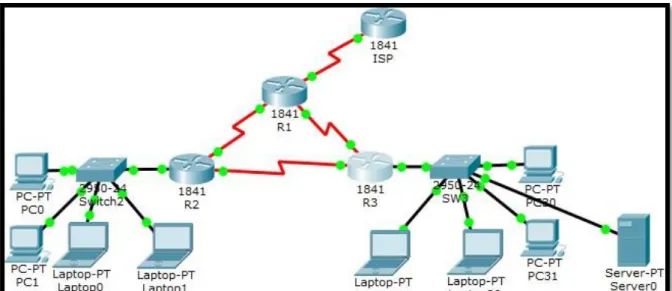
Escenario 2
1. Configurar el direccionamiento IP acorde con la topología de red para cada uno de los dispositivos que forman parte del escenario
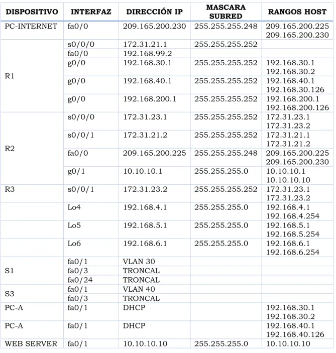
TABLA DE DIRECCIONAMIENTO
DISPOSITIVO INTERFAZ DIRECCIÓN IP MASCARA SUBRED RANGOS HOST
PC-INTERNET fa0/0 209.165.200.230 255.255.255.248 209.165.200.225 209.165.200.230
R1
s0/0/0 172.31.21.1 255.255.255.252
fa0/0 192.168.99.2
g0/0 192.168.30.1 255.255.255.252 192.168.30.1
192.168.30.2
g0/0 192.168.40.1 255.255.255.252 192.168.40.1
192.168.30.126 g0/0 192.168.200.1 255.255.255.252 192.168.200.1
192.168.200.126
R2
s0/0/0 172.31.23.1 255.255.255.252 172.31.23.1 172.31.23.2 s0/0/1 172.31.21.2 255.255.255.252 172.31.21.1
172.31.21.2 fa0/0 209.165.200.225 255.255.255.248 209.165.200.225
209.165.200.230
g0/1 10.10.10.1 255.255.255.0 10.10.10.1
10.10.10.10
R3 s0/0/1 172.31.23.2 255.255.255.252 172.31.23.1
172.31.23.2
Lo4 192.168.4.1 255.255.255.0 192.168.4.1
192.168.4.254
Lo5 192.168.5.1 255.255.255.0 192.168.5.1
192.168.5.254
Lo6 192.168.6.1 255.255.255.0 192.168.6.1
192.168.6.254
S1
fa0/1 VLAN 30
fa0/3 TRONCAL
fa0/24 TRONCAL
S3 fa0/1 VLAN 40
fa0/3 TRONCAL
PC-A fa0/1 DHCP 192.168.30.1
192.168.30.2
PC-A fa0/1 DHCP 192.168.40.1
192.168.40.126
2. Configurar el protocolo de enrutamiento OSPFv2 bajo los siguientes criterios:
OSPFv2 area 0
Configuration Item or Task Specification
Router ID R1 1.1.1.1
Router ID R2
5.5.5.5 Router ID R3
8.8.8.8 Configurar todas las interfaces LAN como pasivas
Establecer el ancho de banda para enlaces seriales en 256 Kb/s Ajustar el costo en la métrica de S0/0 a 9500
R1 R2
R1#config t
Enter configuration commands, one per line. End with CNTL/Z.
R1(config)#router ospf 1
R1(config-router)#router-id 1.1.1.1
R1(config-router)#network 172.31.21.0 0.0.0.3 area 0 R1(config-router)#network 192.168.30.0 0.0.0.255 area 0
R1(config-router)#network 192.168.40.0 0.0.0.255 area 0
R1(config-router)#network 192.168.200.0 0.0.0.255 area 0
R1(config-router)#passive-interface gigabitEthernet0/0.30
R1(config-router)#passive-interface gigabitEthernet 0/0.40
R1(config-router)#passive-interface gigabitEthernet 0/0.200
R1(config-router)#exit R1(config)#int s0/0/0 R1(config-if)#band
R1(config-if)#bandwidth 256 R1(config-if)#ip ospf cost 9500 R1(config-if)#exit
R1(config)#end R1#
R2#config t
Enter configuration commands, one per line. End with CNTL/Z.
R2(config)#router ospf 1
R2(config-router)#router-id 5.5.5.5
R2(config-router)#network 172.31.21.0 0.0.0.3 area 0 R2(config-router)#network 172.31.23.0 0.0.0.3 area 0 R2(config-router)#network 10.10.10.0 0.0.0.255 area 0 R2(config-router)#pass R2(config-router)#passive-interface g0/0 R2(config-router)#int s0/0/0 R2(config-if)#band R2(config-if)#bandwidth 256 R2(config-if)#ip ospf cost 9500 R2(config-if)#exit
R2(config)#end R2#
R3
R3#config t
Enter configuration commands, one per line. End with CNTL/Z.
R3(config)#router ospf 1
R3(config-router)#router-id 8.8.8.8
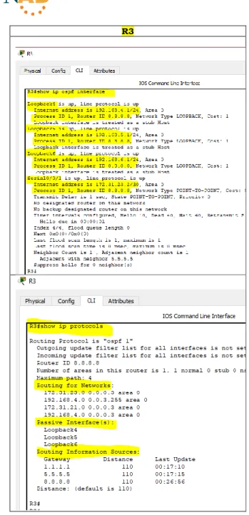
Verificar información de OSPF
• Visualizar tablas de enrutamiento y routers conectados por OSPFv2
R1
R2
• Visualizar lista resumida de interfaces por OSPF en donde se ilustre el costo de cada interfaz
R1 R2
• Visualizar el OSPF Process ID, Router ID, Address summarizations, Routing Networks, and passive interfaces configuradas en cada router.
R3
3. Configurar VLANs, Puertos troncales, puertos de acceso, encapsulamiento, Inter-VLAN Routing y Seguridad en los Switches acorde a la topología de red establecida.
TABLA VLAN
VLAN EQUIPO DIRECCIONAMIENTO NOMBRE
ASIGNACIÓN DE PUERTO.
VLAN EQUIPO Puerto
Troncal S1 Fa0/3 Troncal S1 Fa0/24 30 S1 Fa0/1 Troncal S3 Fa0/3 40 S3 Fa0/1
CONFIGURACIÓN S1
Asignación VLAN S1
VLAN EQUIPO DIRECCIONAMIENTO NOMBRE
30 S1 192.168.30.0/24 Administración 40 S1 192.168.40.0/25 Mercadeo 200 S1 192.168.200.0/26 Mantenimiento
S1 S1#config t
Enter configuration commands, one per line. End with CNTL/Z. S1(config)#vlan 30 S1(config-vlan)#name ADMINISTRACION S1(config-vlan)#exit S1(config)#vlan 40 S1(config-vlan)#name MERCADEO S1(config-vlan)#exit S1(config)#vlan 200 S1(config-vlan)#name MANTENIMIENTO S1(config-vlan)#exit
S1(config)#int vlan 200 S1(config-if)#
%LINK-5-CHANGED: Interface Vlan200, changed state to up
%LINEPROTO-5-UPDOWN: Line protocol on Interface Vlan200, changed state to up S1(config-if)#ip address 192.168.99.2 255.255.255.0
S1(config-if)#no shut S1(config-if)#exit
S1(config)#ip default-gateway 192.168.99.1 S1(config)#exit
S1(config)#int f0/3 S1(config-if)#swi
S1(config-if)#switchport mode trunk S1(config-if)#swi
S1(config-if)#switchport trunk native vlan 1 S1(config-if)#exit
S1(config)#int f0/24 S1(config-if)#swi
S1(config-if)#switchport mode trunk S1(config-if)#
S1(config-if)#sw
S1(config-if)#switchport trunk native vlan 1 S1(config)#int range f0/1-2, f0/4-23
S1(config-if-range)#sw
S1(config-if-range)#switchport mode access S1(config-if-range)#int range f0/1-2, f0/4-23 S1(config-if-range)#swi
S1(config-if-range)#switchport mode access S1(config-if-range)#no shut
S1(config-if-range)#exit S1(config)#int f0/1 S1(config-if)#swi
S1(config-if)#switchport mode access S1(config-if)#sw
S1(config-if)#switchport access vlan 30 S1(config-if)#exit
S1(config)#end S1#
CONFIGURACIÓN SWITCH S3
Asignacion VLAN S3
VLAN EQUIPO DIRECCIONAMIENTO NOMBRE
40 S3 192.168.40.0/25 Mercadeo 200 S3 192.168.200.0/26 Mantenimiento
S3 S3#config t
Enter configuration commands, one per line. End with CNTL/Z. S3(config)#vlan 3 S3(config-vlan)#exit S3(config)#vlan 30 S3(config-vlan)#name ADMINISTRACION S3(config-vlan)#exit S3(config)#vlan 40 S3(config-vlan)#name MERCADEO S3(config-vlan)#exit S3(config)#vlan 200 S3(config-vlan)#name MANTENIMIENTO S3(config)#int vlan 200
S3(config-if)#no shut S3(config-if)#exit S3(config)#int vlan 200
S3(config-if)#ip address 192.168.99.3 255.255.255.0 S3(config-if)#no shut
S3(config-if)#exit S3(config)#ip def
S3(config)#ip default-gateway 192.168.99.1 S3(config)#int f0/3
S3(config-if)#sw
S3(config-if-range)#sw
S3(config-if-range)#switchport mode access S3(config-if-range)#exit
S3(config)#int f0/1 S3(config-if)#sw
S3(config-if)#switchport mode access S3(config-if)#sw
S3(config-if)#switchport access vlan 40 S3(config-if)#exit
S3(config)#end S3#
4. En el Switch 3 deshabilitar DNS lookup
S3 S3#config t
Enter configuration commands, one per line. End with CNTL/Z. S3(config)#no ip domain lookup
S3(config)#exit S3#
5. Asignar direcciones IP a los Switches acorde a los lineamientos.
S1 S1#config t
Enter configuration commands, one per line. End with CNTL/Z. S1(config)#
S1(config)#int vlan 200
S1(config-if)#ip address 192.168.200.0 255.255.255.0 Bad mask /24 for address 192.168.200.0
S1(config-if)#no shut S1(config-if)#exit S1(config)#end S1#
S3 S3#config t
Enter configuration commands, one per line. End with CNTL/Z. S3(config)#int vlan 200
S3(config-if)#ip address 192.168.200.3 255.255.255.0 S3(config-if)#no shut
6. Desactivar todas las interfaces que no sean utilizadas en el esquema de red.
S1
S1#config t
Enter configuration commands, one per line. End with CNTL/Z.
S1(config)#int f0/2 S1(config-if)#shut
%LINK-5-CHANGED: Interface
FastEthernet0/2, changed state to administratively down
S1(config-if)#int range f0/4-23 S1(config-if-range)#shut
S3
S3#config t
Enter configuration commands, one per line. End with CNTL/Z.
S3(config)#int f0/2 S3(config-if)#shut
%LINK-5-CHANGED: Interface
FastEthernet0/2, changed state to administratively down
7. Implement DHCP and NAT for IPv4
R1 R1#config t
Enter configuration commands, one per line. End with CNTL/Z. R1(config)#ip dhcp pool ADMINISTRACION
R1(dhcp-config)#dns-server 10.10.10.11 R1(dhcp-config)#default-router 192.168.30.1
R1(dhcp-config)#network 192.168.30.0 255.255.255.0 R1(dhcp-config)#exit
8. Configurar R1 como servidor DHCP para las VLANs 30 y 40.
R1 R1#config t
Enter configuration commands, one per line. End with CNTL/Z. R1(config)#ip dhcp excluded-address 192.168.30.1 192.168.30.30 R1(config)#ip dhcp pool ADMINISTRACION
R1(dhcp-config)#network 192.168.30.0 255.255.255.0 R1(dhcp-config)#default-router 192.168.30.1
R1(dhcp-config)#dns-server 10.10.10.11 R1(dhcp-config)#end
R1#config t
Enter configuration commands, one per line. End with CNTL/Z. R1(config)#ip dhcp excluded-address 192.168.40.1 192.168.40.30 R1(config)#ip dhcp pool MERCADEO
R1(dhcp-config)#network 192.168.40.4 255.255.255.0 R1(dhcp-config)#def
R1(dhcp-config)#default-router 192.168.40.1 R1(dhcp-config)#dns-server 10.10.10.11 R1(dhcp-config)#end
R1#
9. Reservar las primeras 30 direcciones IP de las VLAN 30 y 40 para configuraciones estáticas.
R1 R1#config t
Enter configuration commands, one per line. End with CNTL/Z. R1(config)#ip dhcp excluded-address 192.168.40.1 192.168.40.30 R1(config)#ip dhcp excluded-address 192.168.30.1 192.168.30.30 R1(config)#exit
ARCHIVOS .pkt
Los ejercicios fueron resueltos gracias al uso de la herramienta Packet Tracer y puedes ser consultados en la siguiente ruta:
CONCLUSIONES
Gracias al desarrollo de esta actividad, hemos fortalecido los conocimientos y las habilidades adquiridas al llevar a cabo satisfactoriamente el DIPLOMADO DE PROFUNDIZACIÓN CISCO (DISEÑO E IMPLEMENTACIÓN DE SOLUCIONES INTEGRADAS LAN / WAN).
BIBLIOGRAFÍA
CICO NETWORKING ACADEMY – CCNA 1
https://static-course-assets.s3.amazonaws.com/ITN503/es/index.html
CICO NETWORKING ACADEMY – CCNA 2
https://static-course-assets.s3.amazonaws.com/RSE503/es/index.html
CISCO CCNA – CONFIGURACIÓN DHCP
http://blog.capacityacademy.com/2014/01/09/cisco-ccna-como-configurar-dhcp-en-ciscorouter/
COMO CONFIGURAR OPSF EN ROUTER
http://blog.capacityacademy.com/2014/06/23/cisco-ccna-como-configurar-ospf-en-ciscorouter/
CONFIGURACIÓN TRONCAL 802.1Q
https://www.cisco.com/c/es_mx/support/docs/switches/catalyst-4000-seriesswitches/24064-171.html
CISCO. (2014). Conceptos de Routing. Principios de Enrutamiento y Conmutación.
https://static-courseassets.s3.amazonaws.com/RSE50ES/module4/index.html#4.0.1.1
CISCO. (2014). Configuración y conceptos básicos de Switching. Principios de
Enrutamiento y Conmutación.