DIPLOMADO DE PROFUNDIZACION CISCO PRUEBA DE HABILIDADES PRÁCTICAS CCNP
LUIS FERNANDO BUSTAMANTE
UNIVERSIDAD NACIONAL ABIERTA Y A DISTANCIA - UNAD ESCUELA DE CIENCIAS BÁSICAS, TECNOLOGÍA E INGENIERÍA - ECBTI INGENIERÍA
DIPLOMADO DE PROFUNDIZACION CISCO PRUEBA DE HABILIDADES PRÁCTICAS CCNP
LUIS FERNANDO BUSTAMANTE
Diplomado de opción de grado presentado para optar el título de INGENIERO ELECTRÓNICO
DIRECTOR:
MSc. GERARDO GRANADOS ACUÑA
UNIVERSIDAD NACIONAL ABIERTA Y A DISTANCIA - UNAD ESCUELA DE CIENCIAS BÁSICAS, TECNOLOGÍA E INGENIERÍA - ECBTI INGENIERÍA
3
NOTA DE ACEPTACIÓN:
Presidente del Jurado
Jurado
Jurado
4
TABLA DE CONTENIDO
TABLA DE CONTENIDO ... 4
LISTA DE FIGURAS ... 5
LISTA DE TABLAS ... 6
GLOSARIO ... 11
RESUMEN ... 12
Palabras clave: ... 12
ABSTRACT ... 13
Keywords:... 13
INTRODUCCIÓN ... 14
1. ESCENARIO UNO ... 15
1.1. Configuración del escenario propuesto... 15
1.2. Ajustar el ancho de banda ... 18
1.3. Configurar las familias de direcciones ... 19
1.4. Configuración OSPF en R2 ... 20
1.5. Configuración OSPF en R3 ... 21
1.6. Configuración Stubby... 21
1.7. Configuración Rutas ... 22
1.8. Configuración EIGRP... 23
1.9. Configuración EIGRP interfaces pasivas. ... 24
1.10. Configuración Redistribución mutua. ... 25
1.11. Configuración Publicidad de las rutas. ... 26
1.12. Parte 2: Verificar conectividad de red y control de la trayectoria. ... 26
2. ESCENARIO DOS ... 31
2.1. Parte 1: Configurar la red de acuerdo con las especificaciones. ... 31
CONCLUSIONES ... 50
5
LISTA DE FIGURAS
Figura 1.Ilustración escenario uno ... 15
Figura 2. Verificación de rutas en R1 ... 27
Figura 3. Verificación de comunicación en R1 ... 27
Figura 4. Verificación de rutas en R2 ... 28
Figura 5. Verificación de comunicación en R2 ... 28
Figura 6. Verificación de comunicación en R2 ... 29
Figura 7. Verificación de rutas en R3 ... 29
Figura 8. Verificación de rutas en R3 ... 30
Figura 9. Verificación de comunicación en R3 ... 30
Figura 10. Topología de red ... 31
Figura 11. Verificación de VLAN’s en DLS1 ... 45
Figura 12. Verificación de VLAN’s en DLS2 ... 46
Figura 13. Verificación de VLAN’s en ALS1 ... 46
Figura 14. Verificación de VLAN’s en ALS2 ... 47
Figura 15. Verificación de EtherChannel entre DLS1 y ALS1 ... 47
Figura 16. Verificación de EtherChannel entre DLS1 y ALS1 ... 48
Figura 17. Verificación de Spanning tree entre DLS1 o DLS2 para cada VLAN .... 48
6
LISTA DE TABLAS
11 GLOSARIO
LAN: Local Area Network, Red de área local. Una LAN es una red que conecta los ordenadores en un área relativamente pequeña y predeterminada (como una habitación, un edificio, o un conjunto de edificios).
WAN: Wide Area Network (“Red de Área Amplia”). El concepto se utiliza para nombrar a la red de computadoras que se extiende en una gran franja de territorio, ya sea a través de una ciudad, un país o, incluso, a nivel mundial.
NAT: (Network Address Translation ó Traducción de Dirección de Red) es un mecanismo utilizado por routers y equipos para intercambiar paquetes entre dos redes que se asignan mutuamente direcciones incompatibles.
VLAN: (Red de área local virtual o LAN virtual) es una red de área local que agrupa un conjunto de equipos de manera lógica y no física. Efectivamente, la comunicación entre los diferentes equipos en una red de área local está regida por la arquitectura física.
DHCP: (Dynamic Host Configuration Protocol). Protocolo de configuración dinámica de host. Protocolo que usan las computadoras para obtener información de configuración. El DHCP permite asignar una dirección IP a una computadora sin requerir que un administrador configure la información sobre la computadora en la base de datos de un servidor.
DNS: Domain Name System” (sistema de nombre de dominio). DNS es un servicio que habilita un enlace entre nombres de dominio y direcciones IP con la que están asociados.
OSPF: Open Shortest Path First (OSPF) es un protocolo de direccionamiento de tipo enlace-estado, desarrollado para las redes IP y basado en el algoritmo de primera vía más corta (SPF).
IP: La dirección IP es un conjunto de números que identifica, de manera lógica y jerárquica, a una Interfaz en red (elemento de comunicación/conexión) de un dispositivo (computadora, tableta, portátil, teléfono inteligente) que utilice el protocolo o (Internet Protocol).
12 RESUMEN
La revolución de las nuevas tecnologías a nivel mundial está cambiando considerablemente la forma de las economías llevándolas a hacer más competitivas, más exigentes y con niveles muy altos de optimización de infraestructura y de las comunicaciones, es por ello por lo que las TIs juegan un papel muy importante en el crecimiento y desarrollo de los diferentes sectores económicos del mundo.
13 ABSTRACT
The revolution of new technologies worldwide is changing considerably the way of economies leading them to make them more competitive, more demanding and with very high levels of infrastructure and communications optimization, which is why ITs play a role very important in the growth and development of the different economic sectors of the world.
The development of activities for the Cisco CCNP Certificate of deepening allows us to understand in depth the different topics through theory and practice, obtaining skills and abilities in LAN / WAN networks through different scenarios proposed in each activity and bringing them to reality through programs such as GNS3, Packet Tracert, among others.
14
INTRODUCCIÓN
El mundo de hoy, tal como lo conocemos, se mantiene en un intercambio constante de información en medios digitales, las redes de cómputo hacen posible esta tarea, cada día aumenta de forma exponencial, ya que se agregan nuevos dispositivos, tales como celulares, televisores, lavadoras y todo lo que comprende el IoT o internet de las cosas, nuevas granjas de servidores más pc’s entre otros. Entendiendo dichos requerimientos, surge una necesidad en el ámbito de las tecnologías de la información y es el de ingenieros que puedan realizar las implementaciones que contribuyan a la integración del mundo cibernético.
El siguiente trabajo escrito, en el cual se desarrollan las habilidades prácticas del diplomado CCNP, plasma el conocimiento adquirido, se puede apreciar, como todas y cada una de las actividades están enfocadas a la solución de problemas de la vida cotidiana de las empresas, las cuales dependen en gran medida de las tecnologías de la información.
15
1. ESCENARIO UNO
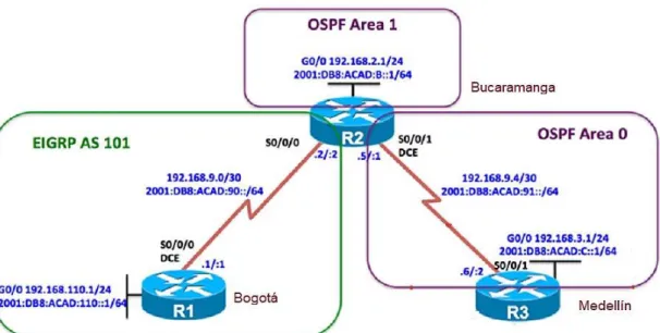
Figura 1.Ilustración escenario uno
Una empresa de confecciones posee tres sucursales distribuidas en las ciudades de Bogotá, Medellín y Bucaramanga, en donde el estudiante será el administrador de la red, el cual deberá configurar e interconectar entre sí cada uno de los dispositivos que forman parte del escenario, acorde con los lineamientos establecidos para el direccionamiento IP, protocolos de enrutamiento y demás aspectos que forman parte de la topología de red.
DESARROLLO DE LAS ACTIVIDADES ESCENARIO UNO
Para el desarrollo de este escenario, lo primero hacemos es armar la topología solicitada en la guía, con 3 routers conectados a través de interfaces seriales asignando direccionamiento IPV4 e IPV6 configurando los sistemas autónomos y ajustando el ancho de banda.
1.1. Configuración del escenario propuesto
Configurar las interfaces con las direcciones IPv4 e IPv6 que se muestran en la topología de red.
16
Debemos guardar siempre la configuración para que luego de un reinicio inesperado, no tengamos que volver a configurar desde cero.
A continuación, el script requerido:
Router 1:
Router> enable
Router# configure terminal Router(config)# hostname R1 R1(config)# inter g0/0
R1(config-if)# ip address 192.168.110.1 255.255.255.0 R1(config-if)# ipv6 address FE80::1 link-local
R1(config-if)# ipv6 address 2001:DB8:ACAD:110::1/64 R1(config-if)# no shut
R1(config-if)# interface serial 3/0
R1(config-if)# ip address 192.168.9.1 255.255.255.252 R1(config-if)# ipv6 address FE80::1 link-local
R1(config-if)# ipv6 address 2001:DB8:ACAD:90::1/64 R1(config-if)# bandwidth 128
R1(config-if)# clock rate 128000 R1(config-if)# no shut
R1(config-if)# end
R1# copy running-config startup-config R1#
Router 2:
Router> enable
Router# configure terminal Router(config)# hostname R2 R2# configure terminal
R2(config)# inter g0/0
17 R2(config-if)# ipv6 address FE80::2 link-local
R2(config-if)# ipv6 address 2001:DB8:ACAD:B::1/64 R2(config-if)# no shut
R2(config-if)# interface serial 3/0
R2(config-if)# ip address 192.168.9.2 255.255.255.252 R2(config-if)# ipv6 address FE80::2 link-local
R2(config-if)# ipv6 address 2001:DB8:ACAD:90::2/64 R2(config-if)# bandwidth 128
R2(config-if)# no shut
R2(config-if)# interface serial 3/1
R2(config-if)# ip address 192.168.9.5 255.255.255.252 R2(config-if)# ipv6 address FE80::2 link-local
R2(config-if)# ipv6 address 2001:DB8:ACAD:91::1/64 R2(config-if)# bandwidth 128
R2(config-if)# clock rate 128000 R2(config-if)# no shut
R2(config-if)# end
R2# copy running-config startup-config R2#
Router 3
Router> enable
Router# configure terminal Router(config)# hostname R3 R3# configure terminal
R3(config)# inter g0/0
R3(config-if)# ip address 192.168.3.1 255.255.255.0 R3(config-if)# ipv6 address FE80::3 link-local
R3(config-if)# ipv6 address 2001:DB8:ACAD:C::1/64 R3(config-if)# no shut
18
R3(config-if)# ip address 192.168.9.6 255.255.255.252 R3(config-if)# ipv6 address FE80::3 link-local
R3(config-if)# ipv6 address 2001:DB8:ACAD:91::2/64 R3(config-if)# bandwidth 128
R3(config-if)# clock rate 128000 R3(config-if)# no shut
R3(config-if)# end
R3# copy running-config startup-config R3#
1.2. Ajustar el ancho de banda
Ajustar el ancho de banda a 128 kbps sobre cada uno de los enlaces seriales ubicados en R1, R2, y R3 y ajustar la velocidad de reloj de las conexiones de DCE según sea apropiado.
Para realizar estas configuraciones se debe ingresar a las interfaces seriales de los router R1, R2, R3 y utilizar el comando bandwith y en las interfaces de R1 serial 3/0 de R2 serial 3/0 y 3/1 y en R3 serial 3/1 en comando clock rate de la siguiente forma:
Router 1:
R1# configure terminal
R1(config)# interface serial 3/0 R1(config-if)# bandwidth 128 R1(config-if)# clock rate 128000 R1(config-if)# end
R1# copy running-config startup-config R1#
Router 2:
R2# configure terminal
19 R2(config-if)# bandwidth 128
R2(config-if)# clock rate 128000 R2(config-if)# end
R2# copy running-config startup-config R2#
Router 3:
R3# configure terminal
R3(config)# interface serial 3/1 R3(config-if)# bandwidth 128 R3(config-if)# clock rate 128000 R3(config-if)# end
R3# copy running-config startup-config R3#
1.3. Configurar las familias de direcciones
En R2 y R3 configurar las familias de direcciones OSPFv3 para IPv4 e IPv6. Utilice el identificador de enrutamiento 2.2.2.2 en R2 y 3.3.3.3 en R3 para ambas familias de direcciones.
Router 2:
R2# configure terminal
R2(config)# ipv6 unicast-routing R2(config)# router ospfv3 1
R2(config-router)# address-family ipv4 unicast R2(config-router-af)# router-id 2.2.2.2
R2(config-router-af)# passive-interface gigabitethernet 0/0 R2(config-router-af)# exit-address-family
R2(config-router)# address-family ipv6 unicast R2(config-router-af)# router-id 2.2.2.2
20 R2(config-router)# end
R2# copy running-config startup-config R2#
Router 3:
R3# configure terminal
R3(config)# ipv6 unicast-routing R3(config)# router ospfv3 1
R3(config-router)# address-family ipv4 unicast R3(config-router-af)# router-id 3.3.3.3
R3(config-router-af)# passive-interface gigabitethernet 0/0 R3(config-router-af)# exit-address-family
R3(config-router)# address-family ipv6 unicast R3(config-router-af)# router-id 3.3.3.3
R3(config-router-af)# passive-interface gigabitethernet 0/0 R3(config-router-af)# exit-address-family
R3(config-router)# end
R3# copy running-config startup-config R3#
1.4. Configuración OSPF en R2
En R2, configurar la interfaz F0/0 en el área 1 de OSPF y la conexión serial entre R2 y R3 en OSPF área 0.
Se realiza la configuración en las interfaces gigabitethernet 0/0 y serial 3/1 para R2 Router 2:
R2# configure terminal
R2(config)# interface gigabitethernet 0/0 R2(config-if)# ospfv3 1 ipv4 area 1 R2(config-if)# ospfv3 1 ipv6 area 1 R2(config-if)# exit
21 R2(config-if)# ospfv3 1 ipv6 area 0
R2(config-if)# end
R2# copy running-config startup-config R2#
1.5. Configuración OSPF en R3
En R3, configurar la interfaz F0/0 y la conexión serial entre R2 y R3 en OSPF área 0.
Router 3:
R3# configure terminal
R3(config)# interface gigabitethernet 0/0 R3(config-if)# ospfv3 1 ipv4 area 0 R3(config-if)# ospfv3 1 ipv6 area 0 R3(config-if)# exit
R3(config)# interface serial 3/1 R3(config-if)# ospfv3 1 ipv4 area 0 R3(config-if)# ospfv3 1 ipv6 area 0 R3(config-if)# end
R3# copy running-config startup-config R3#
1.6. Configuración Stubby.
Configurar el área 1 como un área totalmente Stubby Router 2:
R2# configure terminal R2(config)# router ospfv3 1
22 R2# copy running-config startup-config R2#
Router 3:
R3# configure terminal R3(config)# router ospfv3 1
R3(config-router)# address-family ipv4 unicast R3(config-router-af)# area 1 stub no-summary R3(config-router-af)# exit-address-family R3(config-router)# address-family ipv6 unicast R3(config-router-af)# area 1 stub no-summary R3(config-router-af)# end
R3# copy running-config startup-config R3#
1.7. Configuración Rutas
Propagar rutas por defecto de IPv4 y IPv6 en R3 al interior del dominio OSPFv3. Router 3:
R3# configure terminal
R3(config)# ip route 0.0.0.0 0.0.0.0 192.168.9.5 R3(config)# ipv6 route ::/0 2001:DB8:ACAD:91::1 R3(config)# router ospfv3 1
R3(config-router)# address-family ipv4 unicast R3(config-router-af)# default-information originate R3(config-router-af)# exit-address-family
R3(config-router)# address-family ipv6 unicast R3(config-router-af)# default-information originate R3(config-router-af)# exit-address-family
R3(config-router)# end
23 1.8. Configuración EIGRP
Realizar la configuración del protocolo EIGRP para IPv4 como IPv6. Configurar la interfaz F0/0 de R1 y la conexión entre R1 y R2 para EIGRP con el sistema autónomo 101. Asegúrese de que el resumen automático está desactivado.
Router 1:
R1# configure terminal
R1(config)# router eigrp DUAL-STACK
R1(config-router)# address-family ipv4 unicast autonomous-system 101 R1(config-router-af)# af-interface gigabitEthernet 0/0
R1(config-router-af-interface)# passive-interface R1(config-router-af-interface)# exit-af-interface R1(config-router-af)# topology base
R1(config-router-af-topology)# exit-af-topology R1(config-router-af)# network 192.168.9.0 0.0.0.3 R1(config-router-af)# network 192.168.110.0 0.0.0.255 R1(config-router-af)# eigrp router-id 1.1.1.1
R1(config-router-af)# exit-address-family
R1(config-router)# address-family ipv6 unicast autonomous-system 101 R1(config-router-af)# af-interface gigabitEthernet 0/0
R1(config-router-af-interface)# passive-interface R1(config-router-af-interface)# exit-af-interface R1(config-router-af)# topology base
R1(config-router-af-topology)# exit-af-topology R1(config-router-af)# eigrp router-id 1.1.1.1 R1(config-router-af)# exit-address-family R1(config-router)# end
R1# copy running-config startup-config R1#
Router 2:
R2# configure terminal
24
R2(config-router)# address-family ipv4 unicast autonomous-system 101 R2(config-router-af)# af-interface gigabitEthernet 0/0
R2(config-router-af-interface)# passive-interface R2(config-router-af-interface)# exit-af-interface R2(config-router-af)# topology base
R2(config-router-af-topology)# exit-af-topology R2(config-router-af)# network 192.168.9.0 0.0.0.3 R2(config-router-af)# eigrp router-id 2.2.2.2
R2(config-router-af)# exit-address-family
R2(config-router)# address-family ipv6 unicast autonomous-system 101 R2(config-router-af)# af-interface gigabitEthernet 0/0
R2(config-router-af-interface)# shutdown R2(config-router-af-interface)# exit-af-interface R2(config-router-af)# af-interface serial 3/1 R2(config-router-af-interface)# shutdown R2(config-router-af-interface)# exit-af-interface R2(config-router-af)# eigrp router-id 2.2.2.2 R2(config-router-af)# exit-address-family R2(config-router)# end
R2# copy running-config startup-config R2#
1.9. Configuración EIGRP interfaces pasivas.
Configurar las interfaces pasivas para EIGRP según sea apropiado. Router 1:
R1# configure terminal
R1(config)# router eigrp DUAL-STACK
R1(config-router)# address-family ipv4 unicast autonomous-system 101 R1(config-router-af)# af-interface gigabitethernet 0/0
25
R1(config-router)# address-family ipv6 unicast autonomous-system 101 R1(config-router-af)# af-interface gigabitethernet 0/0
R1(config-router-af-interface)# passive-interface R1(config-router-af-interface)# exit-af-interface R1(config-router-af)# exit-address-family R1(config-router)# end
R1# copy running-config startup-config R1#
Router 2:
R2# configure terminal
R2(config)# router eigrp DUAL-STACK
R2(config-router)# address-family ipv4 unicast autonomous-system 101 R2(config-router-af)# af-interface gigabitethernet 0/0
R2(config-router-af-interface)# passive-interface R2(config-router-af-interface)# exit-af-interface R2(config-router-af)# exit-address-family
R2(config-router)# address-family ipv6 unicast autonomous-system 101 R2(config-router-af)# af-interface gigabitethernet 0/0
R2(config-router-af-interface)# passive-interface R2(config-router-af-interface)# exit
R2(config-router-af)# exit R2(config-router)# end
R2# copy running-config startup-config R2#
1.10. Configuración Redistribución mutua.
26 Router 2:
R2# configure terminal
R2(config)# router eigrp DUAL-STACK
R2(config-router)# address-family ipv4 unicast autonomous-system 101 R2(config-router-af)# topology base
R2(config-router-af-topology)# redistribute ospf 1 metric 10000 100 255 1 1500 R2(config-router-af-topology)# exit-af-topology
R2(config-router-af)# address-family ipv6 unicast autonomous-system 101 R2(config-router-af)# topology base
R2(config-router-af-topology)# redistribute ospf 1 metric 10000 100 255 1 1500 R2(config-router-af-topology)# end
R2# copy running-config startup-config R2#
1.11. Configuración Publicidad de las rutas.
En R2, de hacer publicidad de la ruta 192.168.3.0/24 a R1 mediante una lista de distribución y ACL.
Router 2:
R2# configure terminal
R2(config)# ip access-list standard R3-to-R1
R2(config-std-nacl)# remark to filter 192.168.3.0/24 R2(config-std-nacl)# deny 192.168.3.0 0.0.0.255 R2(config-std-nacl)# permit any
R2(config-std-nacl)# end
R2# copy running-config startup-config R2#
1.12. Parte 2: Verificar conectividad de red y control de la trayectoria.
a. Registrar las tablas de enrutamiento en cada uno de los routers, acorde con los parámetros de configuración establecidos en el escenario propuesto.
27
c. Verificar que las rutas filtradas no están presentes en las tablas de enrutamiento de los routers correctas.
Figura 2. Verificación de rutas en R1
28
Figura 4. Verificación de rutas en R2
29
Figura 6. Verificación de comunicación en R2
30
Figura 8. Verificación de rutas en R3
31
2. ESCENARIO DOS
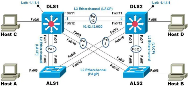
Figura 10. Topología de red
Una empresa de comunicaciones presenta una estructura Core acorde a la topología de red, en donde el estudiante será el administrador de la red, el cual deberá configurar e interconectar entre sí cada uno de los dispositivos que forman parte del escenario, acorde con los lineamientos establecidos para el direccionamiento IP, etherchannels, VLANs y demás aspectos que forman parte del escenario propuesto.
2.1. Parte 1: Configurar la red de acuerdo con las especificaciones. a. Apagar todas las interfaces en cada switch.
Los siguientes comandos deben aplicarse sobre todos los Switch
Switch# configure terminal
Switch(config)# interface range e0/0-3,e1/0-3,e2/0-3,e3/0-3,e4/0-3,e5/0-3 Switch(config-if-range)# shutdown
Switch(config-if-range)# end
32
b. Asignar un nombre a cada switch acorde al escenario establecido.
Esta configuración se realiza con el comando hostname aplicando la configuración dependiendo del switch.
DLS1:
Switch# configure terminal Switch(config)# hostname DLS1 DLS1(config)# end
DLS1# copy running-config startup-config DLS1#
DLS2:
Switch# configure terminal Switch(config)# hostname DLS2 DLS2(config)# end
DLS2# copy running-config startup-config DLS2#
ALS1:
Switch# configure terminal Switch(config)# hostname ALS1 ALS1(config)# end
ALS1# copy running-config startup-config ALS1#
ALS2:
Switch# configure terminal Switch(config)# hostname ALS2 ALS2(config)# end
33
c. Configurar los puertos troncales y Port-Channels tal como se muestra en el diagrama.
1) La conexión entre DLS1 y DLS2 será un EtherChannel capa-3 utilizando LACP. Para DLS1 se utilizará la dirección IP 10.12.12.1/30 y para DLS2 utilizará 10.12.12.2/30.
Los comandos sobre los Switch DLS1 y DLS2
DLS1# configure terminal
DLS1(config)# interface range e2/2-3 DLS1(config-if-range)# no shutdown DLS1(config-if-range)# no switchport
DLS1(config-if-range)# channel-protocol lacp
DLS1(config-if-range)# channel-group 12 mode active DLS1(config-if-range)# interface Port-channel 12
DLS1(config-if)# ip address 10.12.12.1 255.255.255.252 DLS1(config-if)# end
DLS1# copy running-config startup-config DLS1#
DLS2# configure terminal
DLS2(config)# interface range e2/2-3 DLS2(config-if-range)# no shutdown DLS2(config-if-range)# no switchport
DLS2(config-if-range)# channel-protocol lacp
DLS2(config-if-range)# channel-group 12 mode active DLS2(config-if-range)# interface Port-channel 12
DLS2(config-if)# ip address 10.12.12.2 255.255.255.252 DLS2(config-if)# end
34
2) Los Port-Channels en las interfaces Fa0/7 y Fa0/8 utilizarán LACP. Se deben aplicar los siguientes comandos sobre los Switch
Crear Port Channel 1
DLS1# configure terminal
DLS1(config)# interface range e1/2-3 DLS1(config-if-range)# no shutdown
DLS1(config-if-range)# channel-protocol lacp
DLS1(config-if-range)# channel-group 1 mode active DLS1(config-if-range)# end
DLS1# copy running-config startup-config DLS1#
ALS1# configure terminal
ALS1(config)# interface range e1/2-3 ALS1(config-if-range)# no shutdown
ALS1(config-if-range)# channel-protocol lacp
ALS1(config-if-range)# channel-group 1 mode active ALS1(config-if-range)# end
ALS1# copy running-config startup-config ALS1#
Crear Port Channel 2
DLS2# configure terminal
DLS2(config)# interface range e1/2-3 DLS2(config-if-range)# no shutdown
DLS2(config-if-range)# channel-protocol lacp
DLS2(config-if-range)# channel-group 2 mode active DLS2(config-if-range)# end
35
3) Los Port-channels en las interfaces F0/9 y fa0/10 utilizará PAgP. Se deben aplicar los siguientes comandos sobre los Switch
Crear PAgP Port Channel 3
DLS2# configure terminal
DLS2(config)# interface range e2/0-1 DLS2(config-if-range)# no shutdown
DLS2(config-if-range)# channel-protocol pagp
DLS2(config-if-range)# channel-group 3 mode desirable DLS2(config-if-range)# end
DLS2# copy running-config startup-config DLS2#
ALS1# configure terminal
ALS1(config)# interface range e2/0-1 ALS1(config-if-range)# no shutdown
ALS1(config-if-range)# channel-protocol pagp
ALS1(config-if-range)# channel-group 3 mode desirable ALS1(config-if-range)# end
ALS1# copy running-config startup-config ALS1#
Crear PAgP Port Channel 4
DLS1# configure terminal
DLS1(config)# interface range e2/0-1 DLS1(config-if-range)# no shutdown
DLS1(config-if-range)# channel-protocol pagp
DLS1(config-if-range)# channel-group 4 mode desirable DLS1(config-if-range)# end
36 DLS1#
ALS2# configure terminal
ALS2(config)# interface range e2/0-1 ALS2(config-if-range)# no shutdown
ALS2(config-if-range)# channel-protocol pagp
ALS2(config-if-range)# channel-group 4 mode desirable ALS2(config-if-range)# end
ALS2# copy running-config startup-config ALS2#
4) Todos los puertos troncales serán asignados a la VLAN 800 como la VLAN nativa.
Se debe aplicar el siguiente comando sobre todos los switch
DLS1# configure terminal
DLS1(config)# interface range e1/2-3,e2/0-1
DLS1(config-if-range)# switchport trunk encapsulation dot1q DLS1(config-if-range)# switchport mode trunk
DLS1(config-if-range)# switchport trunk native vlan 800 DLS1(config-if-range)# switchport nonegotiate
DLS1(config-if-range)# end
DLS1# copy running-config startup-config DLS1#
DLS2# configure terminal
DLS2(config)# interface range e1/2-3,e2/0-1
DLS2(config-if-range)# switchport trunk encapsulation dot1q DLS2(config-if-range)# switchport mode trunk
37 DLS2(config-if-range)# end
DLS2# copy running-config startup-config DLS2#
ALS1# configure terminal
ALS1(config)# interface range e1/2-3,e2/0-3
ALS1(config-if-range)# switchport trunk encapsulation dot1q ALS1(config-if-range)# switchport mode trunk
ALS1(config-if-range)# switchport trunk native vlan 800 ALS1(config-if-range)# switchport nonegotiate
ALS1(config-if-range)# end
ALS1# copy running-config startup-config ALS1#
ALS2# configure terminal
ALS2(config)# interface range e1/2-3,e2/0-3
ALS2(config-if-range)# switchport trunk encapsulation dot1q ALS2(config-if-range)# switchport mode trunk
ALS2(config-if-range)# switchport trunk native vlan 800 ALS2(config-if-range)# switchport nonegotiate
ALS2(config-if-range)# end
ALS2# copy running-config startup-config ALS2#
d. Configurar DLS1, ALS1, y ALS2 para utilizar VTP versión 3
Esta configuración se realiza con el comando en modo de configuración global vtp versión 3
1) Utilizar el nombre de dominio UNAD con la contraseña cisco123 2) Configurar DLS1 como servidor principal para las VLAN.
38 3) Configurar ALS1 y ALS2 como clientes VTP.
DLS1# vtp primary vlan DLS1# configure terminal
DLS1(config)# vtp domain UNAD DLS1(config)# vtp version 3 DLS1(config)# vtp mode server
DLS1(config)# vtp password cisco123 DLS1(config)# end
DLS1# copy running-config startup-config DLS1#
ALS1# configure terminal ALS1(config)# vtp mode client ALS1(config)# vtp domain UNAD ALS1(config)# vtp version 3
ALS1(config)# vtp password cisco123 ALS1(config)# end
ALS1# copy running-config startup-config ALS1#
ALS2# configure terminal ALS2(config)# vtp mode client ALS2(config)# vtp domain UNAD ALS2(config)# vtp version 3
ALS2(config)# vtp password cisco123 ALS2(config)# end
39
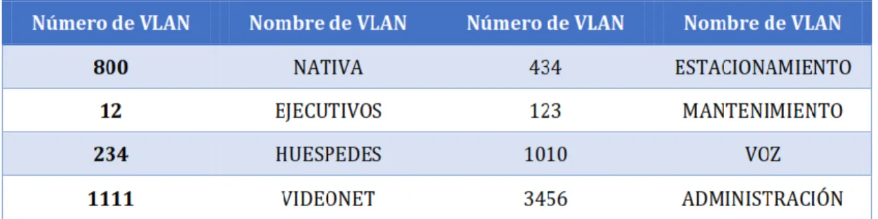
e. Configurar en el servidor principal las siguientes VLAN:
Tabla 1. Información VLAN
DLS1# configure terminal DLS1(config)# vlan 800
DLS1(config-vlan)# name NATIVA DLS1(config-vlan)# vlan 12
DLS1(config-vlan)# name EJECUTIVOS DLS1(config-vlan)# vlan 234
DLS1(config-vlan)# name HUESPEDES DLS1(config-vlan)# vlan 1111
DLS1(config-vlan)# name VIDEONET DLS1(config-vlan)# vlan 434
DLS1(config-vlan)# name ESTACIONAMIENTO DLS1(config-vlan)# vlan 123
DLS1(config-vlan)# name MANTENIMIENTO DLS1(config-vlan)# vlan 1010
DLS1(config-vlan)# name VOZ DLS1(config-vlan)# vlan 3456
DLS1(config-vlan)# name ADMINISTRACION DLS1(config-vlan)#end
DLS1# copy running-config startup-config DLS1#
40 DLS1# configure terminal
DLS1(config)# vlan 434
DLS1(config-vlan)# state suspend DLS1(config-vlan)# end
DLS1# copy running-config startup-config DLS1#
g. Configurar DLS2 en modo VTP transparente VTP utilizando VTP versión 2, y configurar en DLS2 las mismas VLAN que en DLS1.
DLS2# configure terminal
DLS2(config)# vtp domain UNAD DLS2(config)# vtp version 2
DLS2(config)# vtp mode transparent DLS2(config)# vlan 800
DLS2(config-vlan)# name NATIVA DLS2(config-vlan)# vlan 12
DLS2(config-vlan)# name EJECUTIVOS DLS2(config-vlan)# vlan 234
DLS2(config-vlan)# name HUESPEDES DLS2(config-vlan)# vlan 1111
DLS2(config-vlan)# name VIDEONET DLS2(config-vlan)# vlan 434
DLS2(config-vlan)# name ESTACIONAMIENTO DLS2(config-vlan)# vlan 123
DLS2(config-vlan)# name MANTENIMIENTO DLS2(config-vlan)# vlan 1010
DLS2(config-vlan)# name VOZ DLS2(config-vlan)# vlan 3456
DLS2(config-vlan)# name ADMINISTRACION DLS2(config-vlan)#end
41 h. Suspender VLAN 434 en DLS2. DLS2# configure terminal
DLS2(config)# vlan 434
DLS2(config-vlan)# state suspend DLS2(config-vlan)# end
DLS2# copy running-config startup-config DLS2#
i. En DLS2, crear VLAN 567 con el nombre de CONTABILIDAD. La VLAN de CONTABILIDAD no podrá estar disponible en cualquier otro Switch de la red. DLS2# configure terminal
DLS2(config)# vlan 567
DLS2(config-vlan)# name CONTABILIDAD DLS2(config-vlan)#end
DLS2# copy running-config startup-config DLS2#
j. Configurar DLS1 como Spanning tree root para las VLAN 1, 12, 434, 800, 1010, 1111 y 3456 y como raíz secundaria para las VLAN 123 y 234.
DLS1# configure terminal
DLS1(config)# spanning-tree vlan 1,12,434,800,1010,1111,3456 root primary DLS1(config)# spanning-tree vlan 123,234 root secondary
DLS1(config)# end
DLS1# copy running-config startup-config DLS1#
k. Configurar DLS2 como Spanning tree root para las VLAN 123 y 234 y como una raíz secundaria para las VLAN 12, 434, 800, 1010, 1111 y 3456.
DLS2# configure terminal
DLS2(config)# spanning-tree vlan 123,234 root primary
42 DLS2(config)# end
DLS2# copy running-config startup-config DLS2#
l. Configurar todos los puertos como troncales de tal forma que solamente las VLAN que se han creado se les permitirá circular a través de estos puertos. DLS1# configure terminal
DLS1(config)# interface range e1/2-3,e2/0-1
DLS1(config-if-range)# switchport trunk encapsulation dot1q DLS1(config-if-range)# switchport mode trunk
DLS1(config-if-range)# switchport trunk native vlan 800 DLS1(config-if-range)# switchport nonegotiate
DLS1(config-if-range)# end
DLS1# copy running-config startup-config DLS1#
DLS2# configure terminal
DLS2(config)# interface range e1/2-3,e2/0-1
DLS2(config-if-range)# switchport trunk encapsulation dot1q DLS2(config-if-range)# switchport mode trunk
DLS2(config-if-range)# switchport trunk native vlan 800 DLS2(config-if-range)# switchport nonegotiate
DLS2(config-if-range)# end
DLS2# copy running-config startup-config DLS2#
ALS1# configure terminal
ALS1(config)# interface range e1/2-3,e2/0-3
ALS1(config-if-range)# switchport trunk encapsulation dot1q ALS1(config-if-range)# switchport mode trunk
43 ALS1(config-if-range)# end
ALS1# copy running-config startup-config ALS1#
ALS2# configure terminal
ALS2(config)# interface range e1/2-3,e2/0-3
ALS2(config-if-range)# switchport trunk encapsulation dot1q ALS2(config-if-range)# switchport mode trunk
ALS2(config-if-range)# switchport trunk native vlan 800 ALS2(config-if-range)# switchport nonegotiate
ALS2(config-if-range)# end
ALS2# copy running-config startup-config ALS2#
m. Configurar las siguientes interfaces como puertos de acceso, asignados a las VLAN de la siguiente manera:
Tabla 2. Configuración de puertos de acceso
DLS1# configure terminal DLS1(config)# interface e1/1
DLS1(config-if)# switchport access vlan 3456 DLS1(config-if)# no shutdown
DLS1(config-if)# interface e3/2
DLS1(config-if)# switchport access vlan 1111 DLS1(config-if)# no shutdown
DLS1(config-if)# end
44 DLS1#
DLS2# configure terminal DLS2(config)# interface e1/1
DLS2(config-if)# switchport access vlan 12,1010 DLS2(config-if)# no shutdown
DLS2(config-if)# interface e3/2
DLS2(config-if)# switchport access vlan 1111 DLS2(config-if)# no shutdown
DLS2(config-if)# interface range e3/3,e4/0-1
DLS2(config-if-range)# switchport access vlan 567 DLS2(config-if-range)# no shutdown
DLS2(config-if-range)# end
DLS2# copy running-config startup-config DLS2#
ALS1# configure terminal ALS1(config)# interface e1/1
ALS1(config-if)# switchport access vlan 123,1010 ALS1(config-if)# no shutdown
ALS1(config-if)# interface e3/2
ALS1(config-if)# switchport access vlan 1111 ALS1(config-if)# no shutdown
ALS1(config-if)# end
ALS1# copy running-config startup-config ALS1#
ALS2# configure terminal ALS2(config)# interface e1/1
45 ALS2(config-if)# interface e3/2
ALS2(config-if)# switchport access vlan 1111 ALS2(config-if)# no shutdown
ALS2(config-if)# end
ALS2# copy running-config startup-config ALS2#
Part 2: conectividad de red de prueba y las opciones configuradas. a. Verificar la existencia de las VLAN correctas en todos los switches y la asignación de puertos
troncales y de acceso
b. Verificar que el EtherChannel entre DLS1 y ALS1 está configurado correctamente
c. Verificar la configuración de Spanning tree entre DLS1 o DLS2 para cada VLAN.
46
Figura 12. Verificación de VLAN’s en DLS2
47
Figura 14. Verificación de VLAN’s en ALS2
48
Figura 16. Verificación de EtherChannel entre DLS1 y ALS1
49
50
CONCLUSIONES
El uso de protocolos de enrutamiento dinámico nos permite el aprendizaje rápido de la topología de red por la cual estemos pasando y la cantidad de saltos posibles para alcanzar un destino.
Como elemento de seguridad el uso de Vlan nos permite la segmentación adecuada de una red limitando el acceso a los recursos que sean absolutamente necesarios y logrando una división basada en departamentos, servicios o localidades.
Se debe poseer especial cuidado al momento de implementar un esquema de red usando el protocolo VTP ya que al ser el aprendizaje de Vlan dinámico, la introducción de un nuevo Switch con un número de revisión más alto puede afectar el funcionamiento y generar indisponibilidad.
51
BIBLIOGRAFIA
Configuración DHCP en Router (s.f), 27 de Mayo de 2018, recuperado de https://apuntesdecisco.blogspot.com/2008/07/configuracin-de-dhcp-en- lrouter.html
Froom, R., Frahim, E. (2015). CISCO Press (Ed). InterVLAN Routing. Implementing Cisco IP Switched Networks (SWITCH) Foundation Learning Guide CCNP SWITCH 300-115.
Froom, R., Frahim, E. (2015). CISCO Press (Ed). Spanning Tree Implementation. Implementing Cisco IP Switched Networks (SWITCH) Foundation Learning Guide CCNP SWITCH 300-115.
Gerometta Oscar, (2015), 28 de Junio, Que es una SVI, recuperado de http://librosnetworking.blogspot.com/2015/06/que-es-una-svi.html
HSRP Versión 2 (s.f), 27 Mayo de 2018, recuperado de https://www.cisco.com/c/en/us/td/docs/ios-ml/ios/ipapp_fhrp/configuration/xe3s/fhp-xe-3s-book/fhp-hsrp-v2.html