Application feature model for geometrical specification of assemblies
8
0
0
Texto completo
(2) F. Romero et al. / Procedia Engineering 132 (2015) 1128 – 1135. 1129. Several researchers have highlighted the first characteristic, that focuses on product geometry. From the first contributions of Shah and Mäntylä [1], that pointed out that functional information had to be associated to form information, to the most recent ones, that address the Feature validity maintenance issue. Bronsvoort et al. [2] point out the importance of checking validity conditions of the meaning of the Feature itself, that is, checking Feature’s semantics after each modelling operation, embedding such conditions in a Feature class (modelling of semantic Features). These models should allow the incorporation of semantics for reasoning at a higher level, such as the Form Features, Application Features and Assembly Features levels proposed by Brunetti and Grimm [3] in their layer model aimed at organising computer aided systems (CAX). In relation to the second characteristic included in the Feature concept, fully represent design intent, Ma and Tong [4] introduced the concept of Unified Associative Feature, defined as a set of restricted associations between a group of geometrical and non-geometrical entities. This concept allows the establishment of a generic Feature format, valid for the different product development stages, and also the link mechanisms with geometrical models, on the one hand, and with knowledge-based semantic models on the other [5, 6, 7]. This last relation is particularly important in intensive knowledge systems, such as the ones related with collaborative and integrated product-process-resource development (Functional Design, Design Specification, Manufacturing and Inspection Process Planning, etc.). To fully represent and maintain this engineering intent, non-geometrical relations between Features are required and, above all, between Features and other non-geometrical entities that maintain the semantics. These last semantic relations are essential to ensure that Feature based modelling is consistent with design intent [8]. It should be kept in mind that many researchers relate the consistency concept with the establishment of a complete set of relations between Features and semantic entities [8], and that the maintenance of this consistency is still a little addressed issue, though of great importance for product modelling, regardless of it is a Feature based approach or not. This approach in product modelling has its origin in the software field, where Feature Models are used to describe product variables and common properties in a product line and to validate software systems configurations [9]. Other aspects of this domain that are of interest for the Product Engineering field are the proposed definitions, categories and views [10, 11]. Regarding these last issues, in his work Riebisch establishes four Feature categories: Functional Feature, Interface Feature, Parameter Feature and Concept Feature. This idea will be expanded in the next section and is going to be essential for the proposal of a Feature based Domain Meta Model presented in this work. Other key aspect for the integration of several views and applications is the need of establishing a unique domain model that maintains consistency between these views and/or application models. In this regard, Zha and Sriram [12] proposal must be highlighted. These researchers define a Feature Domain Model as the aggregation of the Feature Models of different Application Features integrated in the same domain, establishing a set of inter-feature restrictions that regulate mapping between Application Features of the integrated Feature Models. Other crucial element for the inter-application integration arises from the need of establishing a common semantics for all those activities integrated in the domain. In particular, for the purpose of this work and with the aim of finding a common intention, it will be important to revise both the semantics and the relations that support some of the generic product models present in literature (STEP (Standard for the Exchange of Product model data), MOKA (Methodology and tools Oriented to Knowledge-based engineering Applications), CPM (Core Product Model) and PPO (Product-Process-Organisation)) as well as other models that specialize the previous ones. This is the case of OAM (Open Assembly Model), an extension of CPM for mechanical assemblies, or the one proposed by Zha and Sriram [12] for embedded systems. These concepts and semantics have been considered when developing a valid model proposal for the purposse of this work: product specification and verification. This domain integrates both product specification and inspection process planning, specification and validation activities. These activities involve reasoning about specification chains established on product assembly architectures during product specification activities, and on inspection process assembly architectures during inspection activities. 2. Proposal of a Feature-based Domain Meta-Model for collaborative and integrated product development The proposal (Fig. 1) has been developed based on: a) existing Meta-Models that consider the use of a Feature (Conceptual Feature) that serves as a container (aggregation) of Features of different categories [Ma, Sriram and Riebisch]; and b) the PPO Product Model, integrated in the IPPOP initiative with the process and organization models and whose simplicity contributes to collaborative work [13]..
(3) 1130. F. Romero et al. / Procedia Engineering 132 (2015) 1128 – 1135. Fig. 1. Proposed general diagram of the Feature-based Meta-Model. As already done by other authors [Ma, Sriram], UML (Unified Modelling Language) class diagrams will be used to represent the proposed models. In these diagrams, classes are graphically shown as rectangular boxes and associations relating classes as lines. Aggregation is a particular type of association where the aggregated class, with the diamond characteristic for this relation, consists of a set of classes. Generalization and specialisation relations show inheritance and establish hierarchy between classes. The general class (super class), the one with the triangle, is connected with its specialisations (sub class). The association between two classes can be characterised by another class, called associative class, which is connected to the relation by a dotted line. As it can be seen in Fig. 1, a Feature Model is the aggregation of several Application Features and of the associative classes characterizing the relations between these classes and the ones they contain. The Application Feature class, main class of the meta-model, is a Conceptual Feature according to the categories considered by Riebisch [9] and Zhan and Sriram [12] and, therefore, it is a Feature whose only aim is to contain other features that have a common behaviour in an application. In particular, in the proposal presented in this work, an Application Feature is the aggregation of objects that belong to the Structural Feature, Geometric Interface Feature (an aggregation of Geometries), Function Feature and Parameter Feature classes, that are specialisations of the Object Feature class. The aggregation relation between an Application Feature and its Object Features is characterised by a set of restrictions, not shown in the UML model, and that determine the type and number of Object Features that can be part of an Application Feature. In turn, the aggregation of several Feature Models defines the Domain Model class, including all Feature Models of the same domain or field of interest. In order to ensure compatibility and consistency of the Feature Models in the same domain, and therefore between the Application Feature they are made of, the Model Association associative.
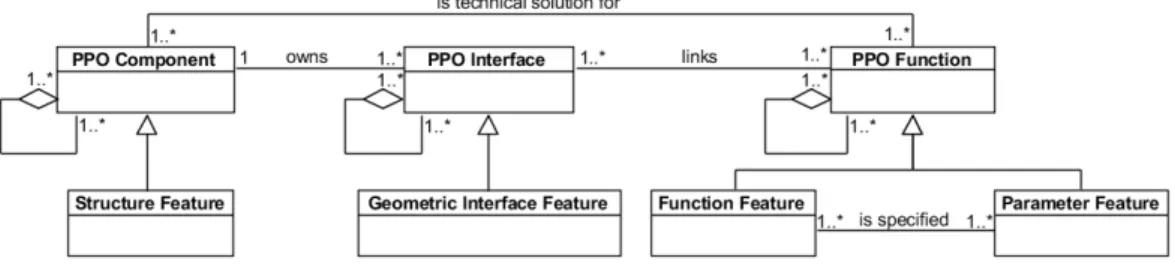
(4) F. Romero et al. / Procedia Engineering 132 (2015) 1128 – 1135. class is defined as an aggregation of Inter-Model Feature Associations. Inter-Model Feature Association and IntraModel Feature Association classes are specialisations of the Application Feature Association class, aggregation of Inter-Feature Restrictions that restrict relations between Feature Objects. In this way, the Inter-Model Feature Association class ensures matching between Application Features of different Feature Models while the Intra-Model Feature Association class ensures compatibility, consistency, etc. between Application Features within the same Feature Model. The Object Feature, in line with the previously referred Ma et al. [7] and Zha and Sriram [12] proposals, is defined as an aggregation of instances of the Attribute class. In order to characterise relations between Object Features, the Object Feature Association class and its subclass Feature Type Association have been defined to contain the instances that restrict relations between Object Features of the same type and between Object Features of different type, respectively. The model also considers the Intra-Feature Restriction class, that is in charge of restricting the type and value of the attributes defining a specific Object Feature. The fact that the Application Feature contains several Object Feature types that have a similar semantics to the basic classes of the PPO Product Model, offered the opportunity of linking both models so that application models of a certain domain, based on the Feature-based Meta-Model, could be provided with the PPO collaborative nature. For that, Object Feature specialisations have been defined as subclasses of the PPO Component, Interface and Function classes. As it can be seen in Fig. 2, Parameter Feature and Function Feature are defined as subtypes of the PPO Function class, since a Function Feature is specified by Parameter Features. On the other hand, the Structure Feature and the Geometric Interface Feature match with PPO Component and PPO Interface respectively. Together they represent the solution developed for a specific functionality, specifying the components (structure) participating in that functionality and the geometrical forms, as interfaces, that allow to obtain it. This geometric interface will contain all geometrical properties through which a component can be linked to other component interface, considering both the nominal geometry (Nominal Feature) and other geometries (Features with defects, etc.) related to them, required for the analysis, synthesis, simulation, etc. exercises typical for this domain. Theses Features, as Form Features, will include properties belonging to the parametric, topological and geometrical levels. Additionally, as a consequence of this relation, the different Object Features will own the attributes that the corresponding PPO classes have and the relations defined in this model [13] that can be seen in Fig. 2. Particularly, its classes will be able to be composed and decomposed (UML aggregation), allowing to carry out the exercises at different detail levels, and to specialise them in three types: a) Common; b) Alternative and c) View. With the two first specialisations the model can represent objects (components, interfaces and functions) that have common and alternative parts. In addition, with the specialisation of type View, these objects can own additional attributes appropriate for different exercises in the domain. This involves that, in a Feature Model, different objects of type Application Feature (e.g. Specification Feature) sharing certain attributes, and other specific ones derived from the alternatives and views they belong to, may exist.. Fig. 2. Diagram showing the relation between the Feature-based Meta-Model and the PPO Product Model. 3. The Specification Feature The Specification Feature (Fig. 3) is a specialisation of the Application Feature and, therefore, is the aggregation of four Features which belong to the each of the Object Feature specialisations: Structure Feature, Geometric Interface Feature, Function Feature and Parameter Feature. It is, therefore, an aggregation that contains all the necessary information to, and as considered in the PPO model, detail product specifications during its development.. 1131.
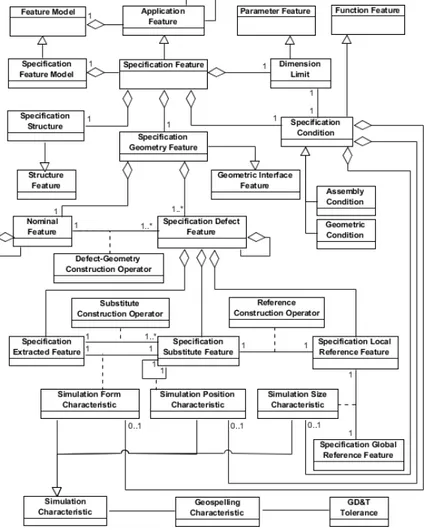
(5) 1132. F. Romero et al. / Procedia Engineering 132 (2015) 1128 – 1135. According to this approach, to fulfil a specific functional condition (Function Feature) related to the precision geometry, it is necessary to establish a technical solution, determined by an architecture of structural components (Structure Feature), that own a geometry that participates in the condition (Geometric Interface Feature). This condition is established in terms of Geospelling characteristics, that are specified by a parameter (Parameter Feature). Hence, in a product assembly model, such as the one that is going to be presented in the following section, the Specification Feature will be a key component, since it contains all the information required for the simulation exercises necessary in the process of geometrical specification. These simulations, that aim to establish limit values for parameters (Parameter Feature), are carried out on geometries with defects on which Geospelling characteristics or tolerance zones, that restrict geometries deviations themselves and relations established between them, are set up. In the specification exercise, these assembly models must consider the assembly architecture, establishing chains (specification chains) in which geometries of Specification Features, that are the interface between artefact or mechanism components (Specification Geometry Feature) and that are established on a Geometric or Assembly Condition, will participate. Thus, in order to ease data processing, each Specification Feature contains both the Feature containing the geometrical information (Specification Geometry Feature) and the one containing the structural elements (Specification Structure). These features give the solution to the functional condition (Specification Condition) and the value that specifies this functional condition (Dimension Limit). This means that the different instances of the Specification Feature class can share instances of the Features aggregated in this class. Depending on how the simulation exercise is carried out, the Specification Defect Features, which, as previously mentioned, are key elements of the Specification Feature, will have to be defined using different types of defect models: a) surface (skin) models, when working with integral geometries or b) skeleton models, when working with derived geometries [14]. In the first case, the Specification Geometry Feature will be the aggregation of a discrete geometry, that describes defect (real) geometry using point clouds or tessellation techniques, or the aggregation of an ideal continuous geometry, that considers position, orientation and dimensions defects. However, in the second case, since geometries of the Features of Size are modelled through its derived geometries (ideal), form or size defects can not be considered. When geometries with defects are represented with ideal geometries, these are the same as the substitute geometries (Specification Substitute Feature) obtained from the discrete geometries extracted (Specification Extracted Feature) in the verification process using a GPS operator (Substitute Construction Operator). Obviously, each simulation model for specification will support certain defect models to represent these geometries, and certain Tolerance Models that restrict their deviations. Although Tolerance Models for discrete geometries have been proposed in the literature [15], most of the methodologies and analysis tools work with continuous geometries and geometrical tolerancing models based on tolerance zones, which have been used in the standardization field [14, 15], or on mathematical representations based on Degrees of Freedom –DoF-, Small Displacement Torsor –SDT-, etc. Therefore, the proposal takes into account two types of geometries with defects, ideal continuous and discrete, and three types of characteristics for the simulation exercises: position, form and size. These characteristics are represented by the classes Simulation Position Characteristic, Simulation Form characteristic and Simulation Size characteristics, that are subtypes of the class Simulation Characteristic. Every Simulation Characteristic, that limits possible deviations of the geometry with defects, is expressed as a Geospelling Characteristic, established as a distance or an angle. Thus, the proposal is, among others, valid for simulation exercises based on geometrical models with defects of type skeleton or continuous surface and tolerance models based on Geospelling characteristics, and also for simulation exercises based on geometrical models of type discrete geometry and models based on tolerance zones. Depending on the type of geometrical and tolerance models used, each exercise will be of one of the views considered in the proposed Feature Model, as it has been mentioned in the previous section. As it has been pointed out, although the proposal has been developed to be able to support different simulation models, including the proposals that are still under investigation [15], the model especially considers the ones based on skeleton or continuous surface geometrical models and on SDT based tolerance models. According to the requirements of the latter, each Specification Defect Feature includes a Specification Local Reference Feature, that determines its situation and establishes the values of the variant and invariant DoF gathered in the SDT. The.
(6) F. Romero et al. / Procedia Engineering 132 (2015) 1128 – 1135. location and orientation characteristics, which can be considered in any of the two models, are established between two situation elements through the associative class Simulation Position Characteristic, which will contain the SDT values. Meanwhile, the Simulation Size Characteristic associative class is used to link the specification local reference to a global reference (Specification Global Reference Feature) and the Simulation Form Characteristic associative class is used to link the Specification Extracted Feature and the corresponding Specification Substitute Feature. On the other hand, as it can be seen in the Specification Model (Fig. 3), to each Geospelling Characteristic a standardised tolerance zone (GD&T Tolerance), that considers tolerance limit variations, can be associated.. Fig. 3. Specification Feature Diagram. 4. Specification Assembly Model In the previous section, a specialisation of the Application Feature has been proposed, the Specification Feature, that gathers all the information required for the specification exercise of an assembly. Unlike other proposals in the literature, the Specification Feature not only considers nominal geometry and assembly components structure, but it also incorporates attributes of geometries with defects by which tolerancing is supported. This aspect is not present in any of the proposals developed by standard initiatives (ISO10303-Part 44, OAM of NIST, etc.), that rather focus on artefact or assembly structural information resulting from the preliminary development [13] and only establish a simple link with standard tolerances specified in the 3D blueprints or models, without considering the multiple requirements needed in the different tolerance analysis and synthesis exercises. These requirements are considered. 1133.
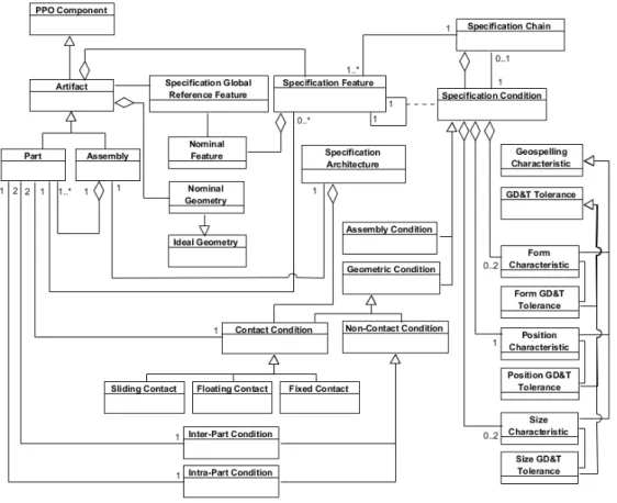
(7) 1134. F. Romero et al. / Procedia Engineering 132 (2015) 1128 – 1135. in the proposal presented in this work (Fig. 4), that is based on: an assembly representation using the Specification Feature explained in the previous section, and the description of specifications using the Geospelling language.. Fig. 4. Specification Assembly Chain Diagram. The model establishes the relations between the Specification Feature and other concepts that participate in the simulation exercises, such as the assembly architecture and specification chains. While the Specification Architecture aggregates all objects of type Contact Condition (Sliding Contact, Floating Contact, Fixed Contact) that associate Specification Features participating in the function, the Specification Chain is an aggregation of Specification Conditions, that include Contact Conditions and other Non-Contact Conditions, Inter- and Intra-Part Conditions, participating in the functional closed loop. For each Specification Condition representing functional conditions (inter- or intra-part), a Specification Chain, aggregating all associations required to close the loop corresponding to that functional condition, will be established. Therefore, from all the Specification Conditions aggregated by a Specification Chain, just one of them is associated to the functional condition and the rest are associated to other Specification Conditions established to create the chain. On the other hand, each of these Specification Conditions, regardless of the type of condition it is related to (Functional or non Functional), will aggregate some Geospelling characteristics that will limit permissible deviations and that can affect: a) Form and Size of the two possible Geometric Interface Features of the Specification Feature; and b) Position between the two possible Geometric Interface Features. These specification characteristics could be transformed into the typical GD&T considered by ASME and ISO standards, based on tolerance zones. As it can be seen in the model, the specification exercise is linked to an assembly, understood as an aggregation of Features and Parts. This assembly can belong to any type of artefact: product or machine-part assembly. This.
(8) F. Romero et al. / Procedia Engineering 132 (2015) 1128 – 1135. circumstance allows the specialisation of the proposed model into assembly models typical for specific production process, such as the machining or inspection process. 5. Conclusions An assembly model for specification based on an Application Feature has been presented. This Application Feature, according to the proposed Feature based Meta-Model and unlike other proposals found in existing literature, contains all the required information to carry out a mechanism simulation in the specification exercise: the structural component that owns it, the nominal interface geometry and/or the geometry with defects interface, and the functional condition for which the component is the solution. In addition, since the proposal is compatible with the PPO model, it ensures its feasibility in collaborative contexts. Furthermore, the proposed model supports the use of different simulation models and techniques, particularly the skin or skeleton continuous geometry ones. On the other hand, the fact that the Specification Assembly Model is based on the Geospelling language, a language that is getting a broad consensus of the scientific community, does not limit its validity, since there are many researches that have undertaken the matching with other specification models and, more specifically, with the ones prevailing in the industrial sector. This matching is also considered in the proposed model. Other of the advantages of the proposal is that being based on an Associative and Unified Feature Model (Feature Meta-Model) allows its easy integration with other Feature models, being possible to configure an integrated model for a specific domain, such as the specification and verification one, where the representation of the geometry with defects is essential and where it is advantageous to carry out dual exercises, as the GPS standard encourages. For this, the authors of this work are currently working on the definition of an Inspection Feature Model and of a Verification Assembly Model that will share with the here presented Specification Feature Model and Specification Assembly Model semantics and relations in order to allow a specification and inspection integrated development. References [1] J.J. Shah, M. Mäntylä, Parametric and Feature-based CAD/CAM, John Wiley & Sons, Canada, 1995, ISBN: 0-471-00214-3. [2] W.F. Bronsvoort, E. Van den Berg, R. Bizarra, A. Noort, Essential developments in feature modelling, The Seventh International Conference on Computer Aided Design and Computer Graphics, 2001 [3] G. Brunetti, S. Grimm, Feature ontologies for the explicit representation of shape semantics, International Journal of Computer Applications in Technology, 2005, Volume 23, pp. 192-202. [4] Y.S. Ma, T. Tong, Associative feature modelling for concurrent engineering integration, Computers in Industry, 2003, Volume 51, pp. 51-71. [5] G. Chen, Y.S. Ma, G. Thimm, S.H. Tang, Unified feature modelling scheme for the integration of CAD and CAx, Computer-Aided Design & Applications, 2004, Volume 1, pp. 595-602. [6] G. Chen, Y.S. Ma, G. Thimm, S.H. Tang, Associations in a unified feature modelling scheme, Journal of Computing and Information Science in Engineering, 2006, Volume 6, pp. 114-126. [7] Y.S. Ma, G.A. Britton, S.B. Tor, L.Y. Lin, Associative assembly design features: concept, implementation and application, International Journal of Advanced Manufacturing Technology, 2007, Volume 32, pp. 434-444. [8] Y.S Ma, G. Chen, G. Thimm, Fine grain feature associations in collaborative design and manufacturing – A unified approach, Collaborative Design and Planning for Digital Manufacturing, Editors: L. Wang, A.Y.C. Nee, Springer-Verlag, London, 2009, ISBN: 978-1-84882-2870_3. [9] M. Riebisch, Towards a more precise definition of feature models, In: M. Riebisch, D.S. James, O. Coplien (Eds.), Modelling Variability for Object-Oriented Product Lines, Norderstadt, 2003, pp. 64-76. [10] K.C Kang, S.G. Cohen, J.A. Hess, W.E. Novak, A.S. Peterson, Feature-oriented domain analysis (FODA) feasibility study, (No. CMU/SEI90-TR-21). Software Engineering Institute, Carnegie-Mellon University, Pittsburgh, 1990. [11] K. Czarnecki, U.W. Eisenecker, Generative Programming. Addison Wesley, 2000. [12] X. F. Zha, R.D. Sriram, Feature-based component model for design of embedded systems, Proc. SPIE 5605, Intelligent Systems in Design and Manufacturing V, 2004, 226, doi: 10.1117/12.571612. [13] C. Zheng, M. Bricogne, J. Le Duigoi, B. Eynard, Survey on mechatronic engineering : A focus on design methods and product models, Advanced Engineering Informatics, 2014, volume 28, pp. 241-257. [14] R. Costadoat, Contribution à la recherche de spécifications pour la gestion des variations géométriques au plus tôt dans le cycle de conception. Mechanics. École normale supérieure de Cachan - ENS Cachan, 2010. French. [15] B. Schleich, N. Anwer, L. Mathieu, S. Wartzack, Skin model shapes: A new paradigm shift for geometric variations modelling in mechanical engineering. Computer-Aided Design, 2014, Volume 50, pp. 1-15.. 1135.
(9)
Figure
Documento similar
In the proposed model, the single workplace bullying feature (BUL) and the deteriorated working conditions (DWC) concept –which encapsulated the selected nine variables
''For any feature in the baryonic mass profile of a galaxy there is a corresponding feature in the rotation curve and vice
In [2], various feature and model compensation approaches were investigated, and the conclusion was that adaptation based on low-rank chan- nel subspace (eigen-channels) is
In this work, we (1) propose a generic feature level fu- sion of Bloom filter-based templates based on face and iris, (2) restricting our aim to the irreversibility of the stored
A meta-model concept is a specification of the minimal requirements that a meta- model should fulfil to qualify for the source or target domain of a generic model-
As shown in Figs. 3 and 6, we see that the BMOMVO- pbest can efficiently explore the Pareto front and find fea- ture subsets, which covers a smaller number of features and reveal
A) Fragmentation or Serialization of news. This is a general feature in all the networks. They break down the news in several weekdays and thus providing small information
In most papers related to texture classi cation, the feature extraction step yields a.. lot of information that must
