MÁSTER UNIVERSITARIO EN INVESTIGACIÓN
QUÍMICA E QUÍMICA INDUSTRIAL
Ángela Arnosa Prieto
Synthesis, Characterization and Study of
Magnetorheological Properties of
Superparamagnetic Photonic Crystals
Advisors:
Manuel Sánchez Andújar and Socorro Castro García
Realization location:
Advanced Scientific Research Center (CICA)
To my tutors, Suqui and Manolo, for everything that they taught me during the time I spent in QUIMOLMAT1. Thanks for transmitting me the beauty of materials science. To Jorge and Alberto, for receiving me with opened arms and for showing me that QUIMOLMAT1 is awesome!
Thanks to Susana, from NANOMAG, for the magnetic measurements.
1. ABSTRACT/RESUMO... 1
1.1 Abstract ... 1
1.2 Resumo ... 2
2. Abbreviations... 3
3. Introduction ... 4
3.1 Photonic crystals ... 4
3.1.1 Definition ... 4
3.1.2 Responsive Photonic Crystals ... 5
3.2 Magnetic Responsive Photonic Crystals (MRPCs) ... 7
3.2.1 Structure and Synthesis ... 7
3.2.2 Mechanism of Magnetic Assembly ... 9
3.3 Basic characterization of nanoparticles ... 12
3.4 Rheology ... 13
4. Objectives ... 17
5. Experimental part ... 18
5.1 Solvents and Reagents ... 18
5.1.1 Solvents ... 18
5.1.2 Reagents... 18
5.2 Synthesis of Fe3O4@PSSMA Nanoparticles ... 18
5.3 Silica Coating Process... 20
6. Instrumental and methods ... 21
6.1 Powder X-Ray Diffraction ... 21
6.2 Infrared Spectroscopy ... 21
6.3 Electron Microscopy ... 22
6.3.1 Transmission Electron Micoscopy ... 22
6.5 Dynamic Light Scattering ... 23
6.6 Electrophoretic Light Scattering ... 23
6.7 Magnetization Curve ... 23
6.8 Magnetic Hyperthermia ... 24
6.9 Rheology ... 24
7. Results and discussion ... 25
7.1 Visual Analysis ... 25
7.2 Powder X-Ray Diffraction ... 25
7.3 Infrared Spectroscopy ... 26
7.4 Transmission Electron Microscopy ... 27
7.5 Scanning Electron Microscopy ... 28
7.6 Thermogravimetric Analysis ... 30
7.7 Dynamic Light Scattering ... 31
7.8 Electrophoretic Light Scattering ... 32
7.9 Magnetization Curve ... 32
7.10 Magnetic Hyperthermia... 33
7.11 Rheological Study ... 34
7.11.1 Flow Sweep Test ... 35
7.11.2 Flow Peak Hold Test ... 36
7.11.3 Amplitude Sweep Test... 37
8. Conclusions/conclusións ... 38
8.1 Conclusions ... 38
8.2 Conclusións ... 39
1
1.
ABSTRACT/RESUMO
1.1
Abstract
In the past decade, responsive photonic crystals (RPCs) have acquired considerable attention. Their unique responsiveness provides a wide range of applications in different fields. RPCs show advantages in anticounterfeiting and information encryption technologies but they are arising as a new trend in biomedicine: detection of different diseases, drug delivery and tumor screening. Among different types of RPCs, colloidal assembled magnetic responsive photonic crystals are the most interesting due to their reversible and tunable response to magnetic fields.
The magnetic responsive photonic crystals prepared in this Master’s Final Project, are characterized by their magnetochromism: a reversible and tunable change in their color in response to the application of a magnetic field.
Superparamagnetic Fe3O4 colloidal nanocrystal clusters (MCNCs) with a core-shell
structure were synthesized. MCNCs were prepared using a modified one-pot solvothermal method where anionic polyelectrolyte poly(4styrenesulfonic acid-co-maleic acid) sodium salt (PSSMA) was used as stabilizer to obtain the core. A modified Stöber process was applied for silica coating to complete the nanostructure.
The obtained nanoparticles were characterized by powder X-Ray Diffraction (XRD), Infrared Spectoscopy (IR), Transmission Electron Microscopy (TEM), Scanning Electron Microscopy (SEM), Thermogravimetric Analysis (TGA), Dynamic Light Scattering (DLS), and Electrophoretic Light Scattering (ELS). Moreover, magnetization curve and magnetic hyperthermia measurements were performed.
The results showed monodisperse magnetic nanoparticles with a superparamagnetic behavior and high heating power. Furthermore, the ordering of the nanoparticles into 3D chain-like structures was observed in the presence of a magnetic field and evenmore this peculiar arrangement can be modified by the applied magnetic field.
2
1.2
Resumo
Na década pasada os cristais fotónicos de resposta (RPCs) adquiriron unha considerable atención. A súa única capacidade de resposta proporciona un amplo rango de aplicacións en diferentes campos. Os RPCs mostran vantaxes na prevención das falsificacións e nas tecnoloxías de encriptación de información, mais preséntanse coma unha nova tendencia na biomedicina: detección de diferentes enfermidades, administración de fármacos e revisión de tumores. Entre os diferentes tipos de RPCs, os cristais fotónicos de resposta magnética con ensamblado coloidal son os máis interesantes debido á súa resposta reversible e regulable aos campos magnéticos.
Os cristais fotónicos de resposta magnética preparados neste Traballo de Fin de Mestrado caracterízanse polo seu magnetocromismo: un cambio reversible e regulable na súa cor en resposta á aplicación dun campo magnético.
Sintetizáronse clusters coloidais superparamagnéticos de nanocristais de magnetita (MCNCs) cunha estrutura de tipo “core-shell”. Preparáronse empregando un proceso solvotermal “one-pot” modificado onde o polielectrolito aniónico empregado foi a sal de sodio do ácido poli(4-estirensulfónico-co-maleico) (PSSMA) como estabilizador para ober o núcleo. Un proceso de Stöber modificado aplicouse para obter o recubrimento de sílice que completa a nanoestrutura.
S nanopartículas obtidas caracterizáronse mediante Difracción de Raios X (XRD) de po, Espectroscopía Infravermella (IR), Microscopía Electrónica de Transmisión (TEM), Microscopía Electrónica de Varrido (SEM), Análise Termogravimétrica (TGA), Dispersión de Luz Dinámica (DLS) e Dispersión de Luz Electroforética (ELS). Ademais realizáronse medidas da curva de magnetización e de hipertermia magnética. Os resultados mostran nanopartículas magnéticas cun comportamento superparamagnético e un alto poder de quecemento. Ademais, observouse o ordenamento das partículas en estruturas 3D en forma de cadeas en presenza dun campo magnético e amais esta peculiar disposición pode ser modificada polo campo magnético aplicado.
3
FTIR: Fourier Transform Infrared Spectroscopy
G’: Elastic modulus or storage modulus
G’’: Viscous modulus or loss modulus
4
3.
INTRODUCTION
3.1
Photonic crystals
3.1.1
Definition
Photonic crystals (PCs) are dielectric materials with a periodically arranged structure in a length scale proportional to the visible wavelengths. These materials are also known as photonic band gap materials because incident light waves of certain frequency interval cannot propagate through the structure, producing photonic band gaps. By controlling the specific directions where photons are not allowed to travel, the flow of light in this optical materials can be manipulated.1–3
This phenomenon is present in nature, where a photonic band gap in the visible range originates materials whose colors change with the viewing angle (Figure 1). The brilliant colors produced by the periodically ordered microstructures in biological materials can be observed in butterflies, marine creatures, bird feathers and even in flora. Opal is another example of natural photonic crystal, where the color effects are produced by the assembly of colloidal spheres of amorphous silica into ordered arrays.1,3
Figure 1.a) Blue color in the fern-like plants of the fenus Selaginella4; b) real color image from a
5
3.1.2
Responsive Photonic Crystals
A responsive photonic crystal (RPC) is a dielectric material with periodical structure that can vary its diffraction wavelength upon exposure to physical or chemical stimuli. A good RPC is identified by reversible tuning, a high response rate, a large tuning range of the diffraction wavelength, and the compatibility with miniaturization for its integration into existing devices.3
RPCs can be classified according to the stimulus that causes the response into:
Thermoresponsive photonic crystals. These photonic crystals undergo a thermo-initiated order-disorder transition that changes the interparticle distance and leads to a variation in the diffraction.7
Chemically responsive photonic crystals. Chemical RPCs use different materials, such as polymers and ceramics. Those grouped on polymeric composition are hydrogel photonic crystals. These PCs present a molecular-recognition group attached to the polymer chains that can selectively bind certain metal ions. The binding causes a change in the osmotic pressure leading to the swelling or shrinkage of the hydrogel and thus, a change in the diffraction.
On the other hand, in ceramic macroporous materials, the infiltration of solvents of different refractive indices induces specific color changes.3
Mechanically responsive photonic crystals. The photonic crystal structures are embedded in a polymer matrix. The stretching of the material produces the variation in the lattice distance of the structure planes, which leads to a reversible tuning of the color. Figure 2 shows the elastic deformation of a colloidal crystal compostite causing the reversible tuning.8
6
Optically responsive photonic crystals. Optical irradiation can be used as a precise and effective stimulus for tuning the structures of PCs when the system presents photosensitive molecules or liquid crystals. The changes in lattice structure or refractive index of the components are light-induced.3
Electrically responsive photonic crystals. Transform the electrical stimulus into an optical response. These RPCs can be divided into different categories depending on the action performed by the electric field: electrochemical process, in which the photonic structure is modified by oxidation and reduction; modification of the refractive index by reorientation of liquid crystal molecules; electrophoretic organization of colloidal suspension and indirectly electrically induced modification of the photonic system.9
Magnetically responsive photonic crystals. The magnetically induced particle interactions in this type of PCs allow the magnetic reversible tuning. These RPCs will be discussed in the next section.
Responsive photonic structures present important technological applications such as anticounterfeiting devices, information encryption technologies, chemical sensors military camouflage and inks and paints. Moreover, RPCs are widely used in biomedicine as biosensors, magnetic resonance imaging (MRI) contrast agents and vehicles for targeted drug delivery. 10–12
In the fabrication of artificial PCs two different approaches can be taken: top-down and bottom-up preparation methods. Top-down approaches use methods such us photolithography and etching techniques, starting from bulk materials to produce microstructures. These procedures have a high cost and low efficiency production, therefore they are not typically used for the fabrication of RPCs.
Bottom-up approaches imply the self-assembly of building blocks into periodic photonic structures. The building blocks can be different molecular species such as block copolymers or nanoscale units such as SiO2. The self-assembly process is the
ordering of the species in organized arrays driven by the positive free energy of mixing of the building blocks.3,13
7
crystals. The other alternative consists in the addition of magnetic components to the already prepared building blocks. The periodic structures are defined and then they are coupled with the responsive materials filling into the interstitial space.
The most advantageous building blocks for the self-assembly of photonic crystals are colloidal spheres since they can be easily synthesized as monodisperse samples.14
3.2
Magnetic Responsive Photonic Crystals (MRPCs)
3.2.1
Structure and Synthesis
This work is focused on a bottom-up method to prepare the responsive materials in the form of the building blocks to assemble the photonic crystals.
The more suitable building blocks for magnetically responsive PCs are monodisperse superparamagnetic colloidal spheres on account of their strong magnetic responses and the possibility of initiating and controlling their dipole-dipole interactions by the action of external fields. A sort of these adequate colloidal spheres are the superparamagnetic colloidal nanocrystal clusters (CNCs) of magnetite (Fe3O4).10,12
The structure of MRPCs is always constituted by a core and a shell, typically a Fe3O4
core and a polymeric shell. The polymer composing the shell is commonly a high polymer, such as poly(4styrenesulfonic acid-co-maleic acid) (PSSMA), which is employed in this work. The polymer that is coating on the core surface acts as the stabilizer, providing the repulsion force in the building-up process under an external magnetic field. In addition, a silica (SiO2) layer is coated on the surface of the Fe3O4
CNCs to prevent the detachment of the polyelectrolyte.12
Each Fe3O4 CNC presents a cluster-like structure constituted by many interconnected
primary nanocrystals with an approximate diameter of 10 nm. As a result of this structure, the CNC retains the superparamagnetic behavior of the nanocrystals at room temperature, while a single-crystalline magnetite particle in the same size range would exhibit a ferromagnetic behavior. 15
8
transition.16 The ferromagnetic or superparamagnetic behavior of nanoparticles depends on their size. As it is represented in Figure 3, a ferromagnetic (FM) material is formed by permanent magnetic moments coupled between them in a parallel arrangement. The FM materials are divided in regions, called magnetic domains, and inside of each domain the individual magnetic moments of the atoms are aligned with one another and they point in the same direction. In the absence of a magnetic field, the magnetization of different domains may point in different directions and thus the total magnetization of the material is zero. With the reduction of the particle size, the number of magnetic domains in the particle decreases until the existence of a domain wall becomes energetically unfavorable, resulting in a single domain particle. The behavior of a single domain particle can be described as if all the atomic moments where rigidly aligned like a unique giant spin. The size of a single domain varies depending on the nature of the material. Therefore, although the overall size of the cluster exceeds the critical size distinguishing ferromagnetic and superparamagnetic magnetite, the magnetic behavior
is determined by the nanocrystals forming the structure.
Figure 3. Ferromagnetic-to-superparamagnetic transition determined by the reduction of the particle size.
On the other hand, the polymer plays an important role in the structure. Due to the presence of the polyelectrolyte, the Fe3O4 CNC has a highly charged surface that favors
9
Several methods for the synthesis of magnetite MRPCs have been developed until now. One-pot high-temperature polyol process for the synthesis of polyelectrolyte-capped superaramagnetic CNCs of magnetite presents a series of advantages regarding other synthetic methods. The process is easy to operate and cost-efficient. The procedure employs a Teflon-lined stainless-steel autoclave. The sealed environment allows the autoclave to generate high pressure to facilitate the growth and crystallization of nanoparticles. The reaction time is shortened with regard to other procedures and this method provides an instantaneous assembling of the MRPCs. However, this method presents some limitations for a large scale synthesis. The cost is very high for larger autoclaves and the high pressure generated by autoclave may produce a safety concern about the devices.12,17
3.2.2
Mechanism of Magnetic Assembly
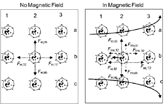
3,10,18The interparticle spacing in a suspension can be changed by magnetically inducing particle interactions, which will result in the magnetic tuning of the PRC. To attain the dynamic structural tuning, a non-close packed colloidal assembly must be embedded in an easily deformable matrix such as a liquid. When a magnetic field is applied to a solution with magnetic colloids, different forces between the particles are present. It is generated a magnetic packing force Fm that pulls the particles toward the maximum of
the local gradient, a magnetic dipole-magnetic dipole attractive force Fma between two
adjacent particles lined up along the magnetic field, and a magnetic dipole-magnetic dipole repulsive force Fmr between two particles that are perpendicular to the field.
Furthermore, an electrostatic repulsive force Fer is usually provoked by the highly
10
Figure 4. Forces on superparamagnetic particles within a colloidal crystal array in the absence and presence of a magnetic field. Fer electrostatic repulsive force, Fm external magnetic force, Fma magnetic
dipole-magnetic dipole repulsive force, Fmr magnetic dipole-magnetic dipole attractive force.18
11
Figure 5. a) Magnetic field distribution around a superparamagnetic particle. Repulsive (b) and attractive (c) dipole-dipole forces between particles drive the formation of particle chains along the magnetic field
(d). The relative strength of the local magnetic field is shown by the color bar on the right.10
The strong interchain repulsion, including both magnetic and electrostatic interactions, causes the stability of chain structures against stacking. When all these forces are similar in strength, the interparticle separation and assembly structure can be altered by any change in the force balance. The disturbance of the magnetic interaction in the force balance produces the magnetically responsive diffraction.
The different colors originated from the diffraction depend on the strength of the magnetic field. When the magnetic field increases, the magnetic attractive force causes the approaching of the neighboring particles in the chains until the electrostatic repulsion is strong enough to balance the magnetic attraction. This effect results in a blue shift in the diffraction. Nevertheless, when the magnetic field decreases, a red shift is produced in the diffraction, that finally disappears when the colloids become disordered. The diffraction tuning and the order-disorder transition are completely reversible.
12
3.3
Basic characterization of nanoparticles
The composition of the nanocrystals that form the nuclei of the magnetic responsive nanoparticles can be known by using the X-ray powder diffraction (XRD). This technique allows the identification of the material forming the core by comparison with a reference pattern.
Another characterization technique is thermogravimetric analysis (TGA), which provides the mass of the metal oxide in the particles and therefore its proportion with respect to the coating. The decomposition temperature of the polymer is also obtained. Infrared spectroscopy (IR) can confirm the inclusion of the polymer in the nanoparticles by monitoring the change in the intensity or position of the bands in the spectrum with respect to the free polymer.
To acquire information about the shape and size of the nanoparticles, electron transmission microscopy (TEM) and electron scanning microscopy (SEM) are two very useful techniques. The obtained images also show the thickness of the coating and the ordering of the particles or the formation of aggregates.
The size distribution profile of the particles can also be obtained with dynamic light scattering if the nanoparticles have spherical shape. The same device used for these measurements may have the possibility of evaluating the zeta potential, which is the charge on the surface of the particles and determines their stability in suspension.
To characterize the magnetic properties, obtaining the magnetization curve is essential since it provides information about the magnetic behavior of the nanoparticles. The magnetization cycle of a superparamagnetic material is different from the one belonging to a ferromagnetic material.
13
3.4
Rheology
Rheology is a useful technique to obtain information about the physical properties of a material. The IUPAC accepts as definition of rheology “the study of the flow and deformation of matter under the influence of a mechanical force. It is concerned particularly with material behavior which cannot be described by the simple linear models of hydrodynamics and elasticity. Some of these departures are due to the presence of colloidal particles or the influence of surfaces”.19
Figure 6. DHR2 Rheometer, TA Instruments20
14
Figure 7. Cone and plate (left) and parallel plates (right) geometries.
When several cones and plates are available, the appropriated diameter must be selected according to the viscosity of the sample, employing higher diameters for lower viscosities. The choice may be reconsidered after the first test.
The stress applied by the head over the fluid can be of several types, being the most common the application of a shear stress. The head’s rotational speed is known as shear rate and it is expressed in units of s-1 (the head’s rotation frequency). Depending on the resistance of the sample to the applied shear rate, different data regarding its physical properties, such as viscosity, can be collected.
Different types of substances can be studied in rheometers: fluids, soft solids and even viscoelastic fluids, which are materials with both fluid and solid characteristics. This technique allows the determination of diverse physical properties of these materials. Focusing on fluids, one of the most important physical properties is the viscosity, which provides a measure of the resistance opposed by the fluid to a shear rate. Viscosity is usually expressed in units of Pa·s. Two kinds of fluids can be distinguished according to the viscosity behavior: Newtonian and non-Newtonian fluids. Newtonian fluids have a constant viscosity so that the shear stress and its strain rate present a lineal relation. An example of a Newtonian fluid is water. In the case of a non-Newtonian fluid the viscosity is variable, depending, for example, on the applied shear stress. In this case it is called apparent viscosity. A viscoelastic fluid is an example of a non-Newtonian fluid.22
In the case of solids, the application of a stress produces deformations. If the deformation is reversible, so that the solid recovers the original shape when the stress is stopped, it is an elastic deformation. The stress/strain relation will have a linear
15
storage modulus, G’) and the viscous modulus (or loss modulus, G’’) can be described. The elastic modulus measures the elasticity of the material, the ability of the material to store energy. The viscous modulus measures the ability of the material to dissipate energy, which is lost as heat. When the elastic modulus is higher than the viscous modulus, the material has a higher solid component and thus it behaves more as a solid than as a liquid. But if the viscous modulus is higher than the elastic modulus, the liquid component is higher and the material behaves more like a liquid.21
There are not many studies concerning the rheological properties of MCNCs suspensions. The fluid behavior, solid or liquid, Newtonian or non-Newtonian is unknown for the prepared magnetite MCNCs suspension. In this case, tests are done in some conditions that are not still optimized.
It is important to consider the linear regime when carrying on the experiments. The linear regime is the range in which the elastic and viscous moduli maintain a parallel behavior and their values are kept constant. An amplitude sweep test must be carried out to know the lineal regime of the MCNCs suspension. This test provides the values for the elastic modulus and viscous modulus against the oscillation stress that determine the solid or liquid-like behavior of the material.
Different tests can be done to understand the behavior of the MCNCs suspension. In this work emphasis will be placed in the following ones:
Flow sweep test: in this test, different shear rates are applied to the sample for a time interval and the apparent viscosity is obtained for each of the velocities. The apparent viscosity is usually expressed in units of Pa·s.
Flow peak hold test: in this test, viscosity is measured at one constant velocity. The velocity that is used in this experiment is selected from the data obtained in the flow sweep test.
16
The implementation of magneto-rheological tests allows the comparison of the suspension behavior in the presence and absence of a magnetic field. This study is interesting because the suspension is a MRPC and the ordering of its structure changes with an external magnetic field. There is a specific accessory for the equipment, shown in Figure 8, which enables that complete characterization of magneto-rheological fluids under the influence of a controlled field. Unfortunately, there was no possibility of doing the magneto-rheological measurements in this work due to the breakdown at this module, but it is planned to do so in the near future.
17
4.
OBJECTIVES
This Master’s Final Project presents as objective:
The synthesis and characterization of magnetic responsive photonic crystals with a superparamagnetic behavior, including the elaboration of a rheological study.
The proposed objectives were developed through the following steps:
Synthesis of the MRPCs by a one-step solvothermal method and application of a silica coating to the previously obtained nanoparticles.
Development of a structural and morphological characterization of the reaction product and study of its magnetic properties.
Understanding of the magnetochromic behavior from the results obtained in the characterization.
18
5.
EXPERIMENTAL PART
5.1
Solvents and Reagents
5.1.1
Solvents
The employed solvents are listed hereunder, purified in its case as indicated. Ethylene glycol (EG) (Panreac, 99%)
Ethanol (EtOH) (Panreac, 99.8%)
Deionized water (Merk Millipore Direct-Q® 5UV equipment)
5.1.2
Reagents
The used reagents are listed hereunder.
Poly(4styrenesulfonic acid-co-maleic acid) sodium salt (PSSMA) (Sigma-Aldrich)
FeCl3·6H2O (Sigma-Aldrich, 98%)
Sodium acetate (NaAc) (Sigma-Aldrich, 99%) Ammonium hydroxide (NH3·H2O) (Panreac, 30%)
Tetraethyl orthosilicate (TEOS) (Acros Organics, 98%)
5.2
Synthesis of Fe
3O
4@PSSMA Nanoparticles
For the Fe3O4 CNCs (Fe3O4@PSSMA) synthesis, a modified one-step solvothermal
method was employed using PSSMA as stabilizer. PSSMA is an anionic polyelectrolyte containing both sulfonate and carboxylate anionic groups (Figure 9).
19
0.5 g of PSSMA was dissolved in 20 mL of EG. The mixture was stirred until a clean solution was obtained. 0.54 g of FeCl3·6H2O were added to the solution before the
addition of 1.5 g of NaAc. The solution was sealed in a Teflon-lined stainless-steel autoclave and heated at 190 ºC for 10h. After reaction, when being cooled to room temperature, the dark precipitates were washed three times with water and centrifuged at 18000 rpm for 30 min at 10 °C. The obtained solid was dispersed in 6 mL of water. A scheme of the synthesis steps is presented in Figure 10, as well as a representation of the structure of the obtained nanoparticles with Fe3O4 nanocrystals embedded in
PSSMA.
Figure 10. Scheme of the synthetic procedure and representation of a nanoparticle structure with Fe3O4
nanocrystals (black) embedded in PSSMA (grey).
The temperature used in the solvothermal synthesis was optimized and the selected one was 190 ºC. Temperatures above 190 ºC lead to the formation of magnetite only, but the polymer is not added to the product. On the other hand, temperatures below 190 ºC are not enough to produce the CNCs: the reaction does not take place and the polymerization of the polymer is produced so the initial solution is transformed into a gel containing the starting materials.
20
5.3
Silica Coating Process
The method used for the silica coating is a modified Stöber process. 1 mL of the Fe3O4@PSSMA water dispersion was added to a solution containing 20 mL of ethanol
1 mL of and water. The mixture was sonicated for 15 min and 1 mL of ammonium hydroxide was added. After sonicating for another 15 minutes, 0.1 mL of TEOS in 5 mL of EtOH was added into the above dispersion and the reaction was performed with continuous sonication for 90 min. The product was washed three times with a mixture 1:1 ethanol/water and centrifuged at 5000 rpm for 20 min at room temperature. The obtained Fe3O4@PSSMA@SiO2 nanoparticles were dispersed in 2 mL of water.
A scheme of the coating procedure steps is presented in Figure 11, as well as a representation of the structure of the obtained nanoparticles with previous Fe3O4@PSSMA nanoparticles coated by a silica layer.
Figure 11. Scheme of the coating procedure and representation of a nanoparticle structure with Fe3O4
nanocrystals (black) embedded in PSSMA (light grey) coated with silica (dark grey).
The coating process was also carried out starting with 2 mL of the Fe3O4@PSSMA
water dispersion and keeping constant the other of the reagents to try to obtain a thinner coating layer. The obtained thinner coating Fe3O4@PSSMA@SiO2 will be named as
21
6.
INSTRUMENTAL AND METHODS
6.1
Powder X-Ray Diffraction
Polycrystalline powder XRD is a non-destructive characterization technique commonly used in the identification of the crystalline phases present in a material and also in the structural determination of each phase. X-rays, with a certain wavelength in the order of the interatomic distances of crystalline solids, fall upon a sample of crystalline powder. Atomic planes act as diffraction gratings and thus X-rays are diffracted producing constructive and destructive interferences, depending on the interatomic distances. Taking into account the angle of incidence of that radiation, the crystalline structure of the materials can be identified.24
The equipment used for the characterization of the compounds by XRD is a SIEMENS D5000 XR diffractometer, placed in the building of the Research Support Services (SAI) of the University of A Coruña (UDC).25
The identification of the crystalline phase was carried out through the analysis of the diffractogram and its comparison with available data at the International Centre for Diffraction Data (ICDD) database, by using the Match! program (version 3.8.0.137).26,27
6.2
Infrared Spectroscopy
IR spectroscopy provides information about the vibration energy of the bonds between light atoms. The identification of the absorption bands produced by the presence of such bonds in a compound gives information about the characteristics of the bonds and their modifications. For the characterization of the prepared compounds, the Fourier transform infrared spectroscopy (FTIR) by attenuated total reflection (ATR) technique was used.
22
6.3
Electron Microscopy
6.3.1
Transmission Electron Micoscopy
The transmission electron microscopy (TEM) provides a direct image of a solid with high magnification. In the TEM microscope, a thin sample is irradiated with electrons of a uniform current density, generated with a tungsten or lanthanum hexaboride filament and accelerated with a potential difference. Electrons interact with the sample in different ways, so electrons can be transmitted, scattered or produce different phenomena. The different interactions are used by the microscope to form images.24 The characterization of the samples was carried out with the 100 kV JEOL JEM 1010 microscope placed in the Research Support Services (SAI) of the UDC.25
6.3.2
Scanning Electron Microscopy
The scanning electron microscopy (SEM) is usually employed to generate a topographic image of the surface of a material. A extremely focused electron beam is produced by a field emission gun. The use of this source of electrons improves the spatial resolution and allows working at very low potentials, which contributes to minimize the charging effect on non-conductive specimens and to prevent damage to electron beam sensitive samples. The electron beam is accelerated with a potential difference and it is sent to the sample surface, performing a sweep in the X and Y directions, and it is finally directed to a detector that registers the result of the interaction24
The SEM images were obtained with the JEOL JSM-7200F multi-purpose FE-SEM microscope placed in the SAI of the University of a Coruña.25
6.4
Thermogravimetric Analysis
23
A TGA was carried out under nitrogen atmosphere by using a STA/TG-DSC (Simultanaous Thermogravimetry Differential Scanning Calorimetry) Netzsch STA 499 Jupiter analyzer, placed in the SAI, UDC.25
6.5
Dynamic Light Scattering
This technique is based in the fluctuation of the light intensity as a consequence of the Brownian movement in the solvent of the suspended particles. That fluctuation is used to obtain a value for the diameter of the particles, which are supposed to be spherical. The measurements were carried out with a NanoBrook 90Plus Zeta Particle Size Analyzer placed in the CICA, UDC.28
6.6
Electrophoretic Light Scattering
The zeta potential is a measurement of the magnitude of the electrostatic forces among charged surfaces. It is established between a solid interface and the liquid that surrounds it. The equipment uses the electrophoretic light scattering to measure the zeta potential. Two electrodes apply an electric field to the sample producing the migration of the charged particles or molecules. Their different mobility is related to the zeta potential. The employed analyzer was the same than for dynamic light scattering technique, a NanoBrook 90Plus Zeta Particle Size Analyzer placed in the CICA, UDC.28
6.7
Magnetization Curve
The magnetization curve is obtained with a vibrating sample magnetometer (VSM) device. The technique is based on the detection of the dipole field from an oscillating magnetic sample placed in a uniform magnetic field.29
24
6.8
Magnetic Hyperthermia
Magnetic hyperthermia is a technique where an alternating magnetic field is applied to a magnetic material (heating agent) to produce a temperature increase. Magnetic nanoparticles (MNPs) are widely used as heating agents. The increase in the temperature is produced by an energy loss, which is released as heat. The energy dissipation is explained by Brownian and Néel relaxation mechanisms. Néel losses correspond to the energy losses from the rotation of the magnetic moment vector of the particle. On the other hand, Brownian losses refer to the energy losses produced by the mechanical rotation of the particles, acting against viscous forces of the liquid medium.31,32
The specific absorption rate (SAR) parameter is quite often used to characterize the heating ability of magnetite MNPs. The SAR provides a numeric value to compare the heating potential of different particles in different conditions, and it can be determined in units of W/g with the following formula:
where c is the specific heat of the solution (the specific heat of water is used when the nanoparticles are dispersed in this medium), msample is the mass of the sample, mmagnetite
is the mass of iron oxide in the sample, and dT/dt is the initial slope of the heating curve.33
Hyperthermia properties were measured on a homemade device placed in the University of Santiago de Compostela.30 An oscillating field with a frequency of 293 kHz and a magnitude of 30 mT was applied to the sample.
6.9
Rheology
The basis on this technique and its utility were explained in section 3.4 of the introduction of this work.
25
7.
RESULTS AND DISCUSSION
7.1
Visual Analysis
The first evidence of the success of the synthesis is the observed change in the color of the product in the presence of a magnetic field. The effect produced by Fe3O4@PSSMA
nanoparticles is shown in Figure 12.
Figure 12. a) Brown color of the Fe3O4@PSSMA suspension in the absence of a magnetic field. Change
of the color to red (b), green or blue (c) in the presence of a magnetic field.
The Fe3O4@PSSMA suspension presents brown color in the absence of a magnetic
field. The color changes when a magnet is approached. The suspension turns red, the green and finally blue as the magnet is closer, which implies that the strength of the magnetic field increases.
7.2
Powder X-Ray Diffraction
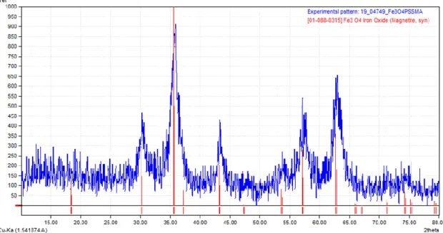
Figure 13 shows the obtained X-ray diffraction pattern for Fe3O4@PSSMA, which is
compared with the reference 01-088-0315 from the International Center for Diffraction Data (ICDD) database. The obtained diffraction maxima are in full agreement with the magnetite phase, which confirms the correct formation of Fe3O4 phase. In addition, the
26
Figure 13. Experimental diffractogram of Fe3O4@PSSMA (blue) and reference pattern from
ICDD (blue).
7.3
Infrared Spectroscopy
In order to characterize and confirm the incorporation of PSSMA on the MCNC, Fourier transform infrared (FTIR) spectroscopic analysis were performed for both PSSMA and Fe3O4@PSSMA. The obtained spectra are shown in Figure 14.
27
The Fe3O4@PSSMA spectrum exhibits characteristic absorption bands of sulfonate and
carboxylate groups of PSSMA. The bands at 1190 and 1125 cm-1 are due to the asymmetric stretching vibrations, and bands at 1040 and 1010 cm-1 are due to the asymmetric and symmetric stretching vibration of carboxylate groups in PSSMA, respectively. The asymmetric stretching vibration of carboxylate groups moved from 1600 cm-1 for PSSMA to 1630 cm-1 for Fe3O4@PSSMA, indicating that the carboxylate
groups of PSSMA were bonded onto the MCNCs surfaces. The band at around 2930 cm-1 is due to the stretching of the –CH2– vibrations and it looks like it
disappeared in the Fe3O4@PSSMA spectrum.
7.4
Transmission Electron Microscopy
TEM images were obtained for both Fe3O4@PSSMA and Fe3O4@PSSMA@SiO2
samples.
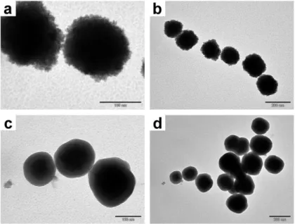
Figure 15a-b shows two TEM images of Fe3O4@PSSMA nanoparticles, which present
spherical shape. Monodisperse particles with a size between 100 and 200 nm are observed and their rough surface identifies the polymer containing the magnetite CNCs.
Figure 15. a-b) TEM images of Fe3O4@PSSMA nanoparticles; c-d) TEM images of
Fe3O4@PSSMA@SiO2 nanoparticles.
TEM images of Fe3O4@PSSMA@SiO2 nanoparticles are exhibit in Figure 15c-d. The
28
sphere in the center of the particle. The coating provides the nanoparticles a smoother surface than in the case of Fe3O4@PSSMA, which can be appreciated in the images.
The shell is dense and fully covers the metallic core. The coated particles maintain the monodispersity previously seen in the Fe3O4@PSSMA nanoparticles and their size
reaches the 200 nm.
7.5
Scanning Electron Microscopy
The samples employed to obtain the SEM images were dried up in the presence of a magnetic field. Figure 16 shows a SEM image of Fe3O4@PSSMA with the result of the
self-assembly of particles into 3D chain-like structures along the external field. Therefore image confirms the ordering of the magnetic nanoparticles in the presence of a magnetic field.
Figure 16. SEM image of the ordering of Fe3O4@PSSMA nanoparticles into chain-like structures.
29
Figure 17. a) Edge of a stack of layers formed in the solid sample; b) Holes in the upper layer of the
solid sample.
Monodisperse Fe3O4@PSSMA and Fe3O4@PSSMA@SiO2 nanoparticles are observed
in Figure 18a-b. Particle sizes were measured from these images obtaining a diameter of 153 nm ± 33 nm for Fe3O4@PSSMA and 206 nm 27 nm for Fe3O4@PSSMA@SiO2.
30
Figure 18. a) SEM image of monodisperse Fe3O4@PSSMA nanoparticles; b) SEM image of
Fe3O4@PSSMA@SiO2 particles with uniform sizes; c) Statistical results for Fe3O4@PSSMA particle
size; d) Diameter of Fe3O4@PSSMA@SiO2 nanoparticles statistically obtained.
7.6
Thermogravimetric Analysis
Figure 19 presents the TGA of Fe3O4@PSSMA. A loss of mass of about a 5% is
31
Figure 19. TGA of Fe3O4@PSSMA.
From the TGA data a ratio of the mass of organic (PSSMA) and inorganic matter (magnetite) in the nanoparticles can be obtained. Fe3O4@PSSMA nanoparticles present
a 13% of organic matter and 87% of inorganic matter.
7.7
Dynamic Light Scattering
The values of the diameters of Fe3O4@PSSMA, Fe3O4@PSSMA@SiO2 and
(TC)Fe3O4@PSSMA@SiO2 nanoparticles were obtained by DLS. All the results are
listed in table 1.
Table 1. Diameters of the different synthesized nanoparticles obtained by DLS.
Particles Diameter (nm)
Fe3O4@PSSMA 190 ± 5 Fe3O4@PSSMA@SiO2 270 ± 5 (TC)Fe3O4@PSSMA@SiO2 220 ± 5
For Fe3O4@PSSMA nanoparticles, a value of 190 nm ± 5 nm was obtained. The coating
layer increases the size of the particles, as it can be observed in the diameter of the Fe3O4@PSSMA@SiO2 nanoparticles, which has a value of 270 nm ± 5 nm.
In the case of (TC)Fe3O4@PSSMA@SiO2 nanoparticles, a value of 220 nm ± 5 nm was
32
changing the proportions between the amount of particles and the reagents of the coating process produces coating layers of different thicknesses.
7.8
Electrophoretic Light Scattering
The values of the zeta potential of the synthesized nanoparticles were obtained by ELS. All the results are listed in table 2.
Table 2. Values of the zeta potential obtained by ELS for the synthesized nanoparticles.
Particles Zeta Potential (mV)
Fe3O4@PSSMA -34 ± 2
Fe3O4@PSSMA@SiO2 -34 ± 2 (TC)Fe3O4@PSSMA@SiO2 -36 ± 3
The zeta potential can take negative or positive values, but in both cases a minimum zeta potential of greater than the absolute value 30.0 mV is required for good physical stability.34 All the obtained nanoparticles present negative values for the zeta potential with values higher than -30.0 mV. This prevents the formation of aggregates making the nanoparticles stable in suspension.
Moreover, the negative zeta potential in the particles with the silica coating will favor the functionalization of the surface.
7.9
Magnetization Curve
The magnetic characterization started with the determination of the magnetization curve for Fe3O4@PSSMA. The result is presented in Figure 20, where a superparamagnetic
33
Figure 20. Magnetization curve of Fe3O4@PSSMA.
It was obtained a value for the saturation magnetization of 68.00 emu/g, a value for the remnant magnetization of 0.65 emu/g and a value for the coercitive field of zero at room temperature. The value for the saturation magnetization is lower compared to the values present in the literature for the bare magnetite (~ 80 emu/g)35, as it was expected, but it is quite high as a result of the good crystallinity of the nanoparticles. The results also indicate the presence of crystalline single domain magnetite since the particle size required to achieve superparamagnetism in Fe3O4 NPs is estimated to be below 20 nm.36
Moreover, the size of the magnetite nanocrystals composing the cluster structure may be of approximately 10 nm so the superparamagnetic behavior is retained at room temperature even though the overall size of the clusters exceeds the 20 nm.3
7.10
Magnetic Hyperthermia
Magnetic hyperthermia measurements were carried out with a Fe3O4@PSSMA sample
under an alternating magnetic field with frequency 293 kHz and magnitude 30 mT. The results, shown in Figure 21, indicate that Fe3O4@PSSMA particles have a high heating
34
Figure 21. Increase in the temperature for Fe3O4@PSSMA produced in hyperthermia measurements.
The SAR coefficient was calculated with the 0.33 M concentration of nanoparticles used for the measurements, obtaining a value of 1.85 W/g. This value is small compared to other SAR coefficients for colloidal Fe3O4 NPs present in the literature.37 This result
is due to the high concentration of the sample used for the measurements, although the increase in the temperature is quite high, since the SAR value depends on the mass of the sample as it was seen in section 6.8.
The high heating power given by the application of a magnetic field along with the magnetochromic properties converts these MNPs into a multifunctional material, opening its field of application.
7.11
Rheological Study
The first step in the measurement of the rheological properties was the design of the rheological study in the absence of a magnetic field by selecting the main parameters: Selection of the geometry of the head: parallel plates geometry was selected for
35
Figure 22. Sample placed in the selected parallel plates geometry.
Tests selection: flow sweep (different shear rates), flow peak hold (constant shear rate) and amplitude sweep tests were carried out to obtain the information in a first approximation.
7.11.1
Flow Sweep Test
When the shear stress is plotted against the shear rate a linear behavior is observed (Figure 23). This result indicates the Newtonian behavior of the material.
Figure 23. Line obtained from the linear fit.
36
7.11.2
Flow Peak Hold Test
Viscosity was measured as a function of time, with a shear rate of 500 s-1. The value of the shear rate was selected from the linear regime obtained in the flow sweep test. Measurements were performed at 20 ºC and the results are shown in table 3.
Table 3. Values of the viscosity of Fe3O4@PSSMA sample at different times.
Time (s) Viscosity (Pa·s)
10 0.00133397
20 0.00133392
30 0.00133247
40 0.00133143
50 0.00133184
60 0.00133127
There is a variation in the viscosity, but it is very small. Thus, the viscosity is considered to be constant and the steady state is reached quickly. Figure 24 shows the small variation in the viscosity values.
Figure 24. Flow peak hold performed with a Fe3O4@PSSMA sample.
37
magnetic field equivalent to the water behavior. This behavior indicates that the nanoparticles exhibit very weak interactions between them at the water suspension. Taking into account this information, the measurements should be repeated with a cone and plate geometry, as it is more appropriate for samples with low viscosity such as water.
In a next step, performing the measurements in the presence of a magnetic field will provide information about how stronger interactions between particles affect the rheological behavior of the material, since in the tests presented in this work the interactions are very weak.
7.11.3
Amplitude Sweep Test
38
8.
CONCLUSIONS/CONCLUSIÓNS
8.1
Conclusions
Magnetic responsive photonic crystals were obtained by one-pot solvothermal synthesis and a silica coating was applied by a modified Stöber process.
A structural and morphological characterization was carried out, showing the correct formation of the nanoparticles. Monodisperse Fe3O4@PSSMA nanoparticles were
obtained with a size of 190 nm ± 5 nm. The monodipersity is maintained after the application of a silica coating, which produces an increase in the diameter of the nanopartiles, which have a size of 270 nm ± 5 nm. The zeta potential is negative in both non-coated and coated nanoparticles, which prevents the formation of aggregates. In the case of Fe3O4@PSSMA@SiO2 it also favors the surface
functionalization.
The magnetic characterization of Fe3O4@PSSMA shows a superparamagnetic
behavior with a value for the remnant magnetization of 0.65 emu·g-1 at room temperature, indicating the presence of single domain magnetite with a particle size in the order of 10 nm. Fe3O4@PSSMA nanoparticles have a high heating power
with a temperature increase of 30 ºC in 300 s.
The observed magnetochromism is produced by the ordering of the particles under the applied magnetic field into chain-like structures ordered forming a 3D network. A rheological study was designed to analyze the viscosity of the Fe3O4@PSSMA
suspension. The rheological results for the suspension show a similar behavior to water in the absence of a magnetic field.
This Master’s Final Project opens perspectives forfuture work. Firstly, to accomplish the rheological measurements in the presence of a magnetic field to determine the rheological properties resulting from to the strong interactions between particles. Secondly, the possibility of functionalize the surface of Fe3O4@PSSMA@SiO2
39
8.2
Conclusións
Obtivéronse cristais fotónicos superparamagnéticos mediante una síntese solvotermal “one-pot” e aplicouse un recubrimento de sílice empregando o proceso de Stöber modificado.
Levouse a cabo unha caracterización estrutural e morfolóxica, indicando a correcta formación das nanopartículas. Obtivéronse nanopartículas Fe3O4@PSSMA
monodispersas cun tamaño de 190 nm ± 5 nm. A monodispersidade mantense tras a aplicación dun recubrimento de sílice, que produce un incremento no diámetro das nanopartículas, que teñen un tamaño de 270 nm ± 5 nm. O potencial zeta é negativo tanto no caso das partículas sen recubrir coma recubertas, o que evita a formación de agregados. No caso das Fe3O4@PSSMA@SiO2 tamén favorece a funcionalización
da superficie.
A caracterización magnética das Fe3O4@PSSMA mostra un comportamento
superparamagnético cun valor para a magnetización remanente de 0.65 emu·g-1 a temperatura ambiente, indicando a presenza de magnetita monodominio cun tamaño de partícula da orde dos 10 nm. As nanopartículas Fe3O4@PSSMA teñen un alto
poder de quecemento, cun incremento da temperatura de 30 ºC en 300 s.
O magnetocromismo observado está producido polo ordenamento das partículas baixo o campo magnético aplicado en estruturas 3D en forma de cadeas.
Deseñouse un estudo reolóxico en ausencia de campo magnético para analizar a viscosidade da suspensión de Fe3O4@PSSMA. Os resultados reolóxicos mostran
para a suspensión un comportamento similar á auga.
Este Traballo de Fin de Mestrado abre perspectivas para otraballo futuro. En primeiro lugar, a realización das medidas reolóxicas en presenza dun campo magnético para determinar as propiedades reolóxicas resultantes das fortes interaccións entre as partículas. En segundo lugar, a posibilidade de funcionalizar a superficie das
nanopartículas Fe3O4@PSSMA@SiO2. En terceiro lugar, o afondamento no estudo
40
9.
BIBLIOGRAPHY
(1) Aguirre, C. I.; Reguera, E.; Stein, A. Tunable Colors in Opals and Inverse Opal Photonic Crystals. Adv. Funct. Mater.2010, 20 (16), 2565–2578.
(2) Fang, M.; Volotinen, T. T.; Kulkarni, S. K.; Belova, L.; Rao, K. V. Effect of Embedding Fe3O4 Nanoparticles in Silica Spheres on the Optical Transmission Properties of Three-Dimensional Magnetic Photonic Crystals. J. Appl. Phys.
2010, 108 (10), 103501.
(3) Ge, J.; Yin, Y. Responsive Photonic Crystals. Angewadante Chemie Int. Ed.
2011, 50 (7), 1492–1522.
(4) Vukusic, P.; Sambles, J. R. Photonic Structures in Nature. In Nature; 2003; Vol. 424, p 852.
(5) Luo, Z.; Evans, B. A.; Chang, C. H. Magnetically Actuated Dynamic Iridescence Inspired by the Neon Tetra. ACS Nano2019, 13 (4), 4657–4666.
(6) Wilts, B. D.; Michielsen, K.; De Raedt, H.; Stavenga, D. G. Sparkling Feather Reflections of a Bird-of-Paradise Explained by Finite-Difference Time-Domain Modeling. Proc. Natl. Acad. Sci.2014, 111 (12), 4363–4368.
(7) Debord, J. D.; Lyon, L. A. Thermoresponsive Photonic Crystals. J. Phys. Chem. B2000, 104 (27), 6327–6331.
(8) Fudouzi, H.; Sawada, T. Photonic Rubber Sheets with Tunable Color by Elastic Deformation. Langmuir2006, 22 (3), 1365–1368.
(9) Nucara, L.; Greco, F.; Mattoli, V. Electrically Responsive Photonic Crystals: A Review. Journal of Materials Chemistry C. Royal Society of Chemistry 2015, 8449–8467.
(10) He, L.; Wang, M.; Ge, J.; Yin, Y. Magnetic Assembly Route to Colloidal Responsive Photonic Nanostructures. Acc. Chem. Res.2012, 45 (9), 1431–1440. (11) Gao, J.; Ran, X.; Shi, C.; Cheng, H.; Cheng, T.; Su, Y. One-Step Solvothermal
Synthesis of Highly Water-Soluble, Negatively Charged Superparamagnetic Fe3O4colloidal Nanocrystal Clusters. Nanoscale2013, 5 (15), 7026–7033.
(12) Tang, S.; Wang, C.; Liu, N.; Li, Y.; Han, P.; Lu, Q. Instantaneous Magnetically Assembled and Hydrophilic Photonic Crystals with Controlled Diffraction Colors. J. Phys. Chem. C2018, 122 (31), 18021–18028.
41
of Photonic Crystals. Chemical Society Reviews. 2013, pp 2528–2554.
(14) Xia, Y.; Gates, B.; Yin, Y.; Lu, Y. Monodispersed Colloidal Spheres: Old Materials with New Applications. Adv. Mater.2000, 12 (10), 693–713.
(15) Ge, J.; Hu, Y.; Biasini, M.; Beyermann, W. P.; Yin, Y. Superparamagnetic Approach to the Synthesis of Highly Tunable Nanocrystal Clusters for Magnetic Responsive Photonic Crystals. RSC Adv.2016, 6 (69), 64434–64440.
(18) Xu, X.; Friedman, G.; Humfeld, K. D.; Majetich, S. A.; Asher, S. A. Synthesis and Utilization of Monodisperse Superparamagnetic Colloidal Particles for Magnetically Controllable Photonic Crystals. Chem. Mater. 2002, 14 (3), 1249– 1256.
(19) Rheology definition http://goldbook.iupac.org/R05381.html (accessed Jun 24, 2019).
(20) Discovery HR-2 – TA Instruments https://www.tainstruments.com/dhr-2/ (accessed Jun 24, 2019).
(21) Salgado-Beceiro, J. Deseño e Estudo Reolóxico de Materiais Cerámicos Para Impresión 3D, Universidade da Coruña, 2018.
(22) Barnes, H. A.; Hutton, J. F.; Walters, K. An Introduction to Rheology, Fourth Edi.; Walters, K., Ed.; Elveiser: The Netherlands, 1989.
(23) Magneto-Rheology – TA Instruments https://www.tainstruments.com/magneto-rheology/ (accessed Jun 24, 2019).
(24) Smart, L. E.; Moore, E. A. Solid Satate Chemistry: An Introduction, 4th editio.; CRC Press: Florida, 2005.
(25) SAI - Servizos de Apoio á Investigación https://www.sai.udc.es/ (accessed Jul 1, 2019).
(26) The International Centre for Diffraction Data - ICDD http://www.icdd.com/ (accessed Jul 3, 2019).
(27) Match! - Phase Identification from Powder Diffraction http://www.crystalimpact.com/match/ (accessed Jul 3, 2019).
42 1, 2019).
(29) Foner, S. Vibrating Sample Magnetometer. Rev. Sci. Instrum. 1956, 27 (7), 548– 548.
(30) Universidade de Santiago de Compostela - Home - USC http://www.usc.es/en/index.html (accessed Jul 1, 2019).
(31) Périgo, E. A.; Hemery, G.; Sandre, O.; Ortega, D.; Garaio, E.; Plazaola, F.; Teran, F. J. Fundamentals and Advances in Magnetic Hyperthermia. Appl. Phys. Rev.2015, 2 (4), 041302.
(32) Goya, G. F.; Lima, E.; Arelaro, A. D.; Torres, T.; Rechenberg, H. R.; Rossi, L.; Marquina, C.; Ibarra, M. R.; Nanociencia, I. De; Ina, D. A.; et al. Magnetic Hyperthermia with Fe3O4 Nanoparticles: The Influence of Particle Size on Energy Absorption. IEEE Trans. Magn.2008, 44 (11), 4444–4447.
(33) Kallumadil, M.; Tada, M.; Nakagawa, T.; Abe, M.; Southern, P.; Pankhurst, Q. A. Suitability of Commercial Colloids for Magnetic Hyperthermia. J. Magn. Magn. Mater.2009, 321 (10), 1509–1513.
(34) Freitas, C.; Müller, R. H. Effect of Light and Temperature on Zeta Potential and Physical Stability in Solid Lipid Nanoparticle (SLN®) Dispersions. Int. J. Pharm.1998, 168 (2), 221–229.
(35) Yáñez-Vilar, S.; Sánchez-Andújar, M.; Castro-García, S.; Mira, J.; Rivas, J.; Señarís-Rodríguez, M. A. Magnetocapacidad En Nanopartículas de Fe3O4 y NiFe2O4. Bol. la Soc. Esp. Ceram. y Vidr.2010, 49 (1), 81–88.
(36) Li, Q.; Kartikowati, C. W.; Horie, S.; Ogi, T.; Iwaki, T.; Okuyama, K. Correlation between Particle Size/Domain Structure and Magnetic Properties of Highly Crystalline Fe3O4 Nanoparticles. Sci. Rep.2017, 7 (1), 9894.
(37) Kolen’Ko, Y. V.; Bañobre-López, M.; Rodríguez-Abreu, C.; Carbó-Argibay, E.; Sailsman, A.; Piñeiro-Redondo, Y.; Cerqueira, M. F.; Petrovykh, D. Y.; Kovnir, K.; Lebedev, O. I.; et al. Large-Scale Synthesis of Colloidal Fe3O4 Nanoparticles Exhibiting High Heating Efficiency in Magnetic Hyperthermia. J. Phys. Chem. C
2014, 118 (16), 8691–8701.