Ladle furnace slag in asphalt mixes
24
0
0
Texto completo
(2) 25. Abstract. 26. Ladle Furnace Slag (LFS) may be used in substitution of fine aggregate (2‐0.063 mm), and filler. 27. (<0.063 mm) in bituminous mixtures, considering its suitable particle size and hydraulic. 28. properties. From among the range of bituminous mixtures, this research is conducted on. 29. Porous Asphalt mixes (PA). Their high void ratio means they can absorb any eventual. 30. expansion of the LFS.. 31. Mechanical behavior, moisture susceptibility and durability are all tested. The results report. 32. the performance of the LFS mixtures, which showed compliance with the specifications of the. 33. relevant standards and no significant differences from those made of natural aggregates and. 34. cement.. 35. Keywords: Ladle Furnace Slag (LFS), Porous Asphalt Mix, Bituminous Permeable Course, Open. 36. Graded Asphalt Concrete, Steel slag, Refining slag, steelmaking reducing slag, filler. 37. substitution, fine aggregate replacement, waste management.. 38. 2.
(3) 39. 1. Introduction. 40. Rational use of natural resources within the construction industry, as in other productive. 41. processes, is becoming a high priority. This trend is reflected in efforts to reuse by‐products. 42. and waste and to reduce landfilling. “Sustainable construction” has an inherent need for. 43. scientific support to facilitate the reuse of these by‐products, combining sustainability and. 44. compliance with technical requirements.. 45. In its continuous expansion, the global steel industry produced 1.6 billion tons of steel in 2014.. 46. There is plenty of previous experience, backed by extensive research, in the reuse of certain. 47. byproducts from iron and steelmaking, basically Blast Furnace Slag (BFS), Electric Arc Furnace. 48. Slag (EAFS) and converter slag (Basic Oxygen Furnaces Slag‐ BOFS) [1‐7]. However, the reuse of. 49. Ladle Furnace Slag (basic slag, reducing slag, white slag or refining slag), a by‐product of. 50. steelmaking from secondary metallurgy processes, is less widespread.. 51. Approximately 60‐80 kg of LFS are recovered for each ton of steel that is refined. Varying. 52. amounts of LFS are usually reintroduced into the steel production process, in both electric arc. 53. furnaces [8‐10] and basic oxygen furnaces [11, 12]. This practice is reported to produce. 54. beneficial effects on the characteristics of the new steels that are produced and in the black. 55. slag that is generated, as well as a reduction in production costs [8].. 56. Despite the above‐mentioned process, an important amount of LF slag is dumped at landfill. 57. sites close to production centers, with its consequent environmental and visual impacts. In. 58. Spain, LFS landfill dumping is in excess of 400,000 tons annually, prompting a search for. 59. alternative uses to reduce this volume of waste and excessive land filling.. 60. One of the main properties of LFS is its hydraulicity, resulting from its chemical composition,. 61. which provides it with cementitious properties [13, 14]. Hydration may also provoke the. 62. dissolution of some elements and volumetric expansion. LFS usually contains certain unstable. 3.
(4) 63. minerals (mainly in the form of free lime and periclase). These minerals are transformed into. 64. Ca(OH)2 and/or Mg(OH)2 in the presence of moisture, which occupy a larger volume than the. 65. primary components [15]. As sufficient volumetric stability is essential in construction, it is. 66. required to study the behavior of the LFS in the composite [15, 16].. 67. Based on the aforementioned cementitious properties, one modern‐day application for LFS. 68. would be as an active or inert addition in the preparation of Portland cement clinker [17, 18].. 69. In fact, cement production is the only use of LFS that is currently approved in Spanish. 70. regulations [19].. 71. Within the construction industry, these cementitious properties and their initial possibilities. 72. are explored, so that the application of LFS would be (complete or partial) replacement of. 73. cement and lime in their varied applications. Other investigations include its suitability as a. 74. substitute of fine natural aggregate, in view of its particle size.. 75. The most highly developed LFS applications in construction are: in replacement of cement. 76. and/or sand in the manufacture of mortars [13, 20‐24] and concrete [25‐27], and even self‐. 77. compacting concrete [28, 29], soil stabilization for road platforms and rural road pavements. 78. [15, 16, 30], and several uses related to environmental engineering such as water treatment. 79. [31‐33], agronomic correctors and supplements [34], and as a fine element for landfill covers. 80. [35].. 81. Road construction requires various different materials; among these materials, bituminous. 82. mixes are mainly composed of aggregates, traditionally extracted from quarries and gravel. 83. pits. Along with the exploitation of limited natural resources, mining, crushing, sieving,. 84. washing and transporting natural aggregates expend significant amounts of energy. Global. 85. consumption of natural aggregates is estimated to exceed 30,000 million tons/year.. 4.
(5) 86. Numerous lines of research have investigated substitution of the fine fraction and the filler of. 87. bituminous mixes by recycled materials: quarry by‐products and mine tailings [36‐38], foundry. 88. sand [39, 40], coal fly ash [41‐43], municipal solid waste incineration ash [44‐46], cement. 89. bypass dust [43, 47], waste glass [48‐50], recycled concrete and mortar [51, 52], waste ceramic. 90. materials (bricks, tiles…) [53, 54], asphalt shingles [55], crushed steel slags [56‐60] and. 91. nonferrous slags (copper, nickel, zinc). However, the Authors are unaware of the existence of a. 92. line of investigation that introduces LFS into bituminous mixtures.. 93. Porous Asphalt (PA) mixes, also known as Permeable Friction Courses (PFC) are special types of. 94. hot bituminous mixtures that have a coarse granular skeleton that develops stone‐on‐stone. 95. contact, and a high content of connected air voids, meaning that these mixtures have good. 96. drainage properties [61].. 97. The main advantages of these kinds of mixtures are related to safety in wet‐weather driving,. 98. owing to the reduction of splash and spray, the risk of hydroplaning and wet skidding; effective. 99. drainage also improves the visibility of pavement markings in wet weather [61]. Improvements. 100. to water quality after drainage have also been demonstrated [62]. In addition to this, they also. 101. contribute to noise abatement, reportedly between 4 to 6 dB(A) when compared to a concrete. 102. pavement or dense‐graded asphalt concrete [63, 64].. 103. The object of this article is to demonstrate the suitability of Ladle Furnace Slag (LFS) for use in. 104. manufacturing porous bituminous mixtures. The following observations were made in this. 105. research when using LFS, due to its volumetric instability:. 106. ‐. Its proportion in the total asphalt mixture was never in excess of 15%.. 107. ‐. The use of slag wrapped in a bituminous matrix is less problematic than its use as an. 108. unbound material, as its surrounding binder protects it from moisture and prevents. 109. hydration reactions. This protection is more noticeable in the case of fine materials, such. 110. as LFS.. 5.
(6) 111. ‐. Its use in flexible and porous matrices, such as porous bituminous mixtures (with an. 112. approximate void ratio of 20%) means any eventual expansion will be absorbed into the. 113. mix voids.. 114. The research followed two approaches. Firstly, the LFS was used as filler, to replace the. 115. cement that is usually employed as quality filler. Then, whole‐particle‐size LFS was used in. 116. substitution of the fine natural aggregate and the filler. All the bituminous mixtures were. 117. tested in terms of mechanical behavior, moisture susceptibility and durability, comparing their. 118. results with the standard mix. The final aim was to demonstrate that porous bituminous. 119. mixtures manufactured with ladle slag presented a strong, stable, durable and environmentally. 120. efficient behavior.. 121. 2. Materials and Methodology. 122. 2.1. Natural aggregates, cement and binder. 123. Asphalt mixes are composed of a combination of coarse aggregates (16/2 mm), fine aggregates. 124. (2/0.063 mm), filler (<0.063 mm), and binder.. 125. The following materials were used in this research: a natural siliceous aggregate from a nearby. 126. quarry, the characteristics of which are summarized in Table 1. It was used as coarse aggregate. 127. in all of the samples and as fine aggregate in the control samples. Ordinary Portland cement,. 128. CEM I/42.5 R was used as filler in the control samples.. 129. Every specimen was manufactured using a Polymer Modified Bitumen complying with EN. 130. 14023 [65] and obtained by a chemical reaction between a hydrocarbon binder and an. 131. elastomeric polymer; penetration 45/80 and softening point 60ºC (PMB 45/80‐60 [65]).. 132. 2.2. Ladle Furnace Slag (LFS). 6.
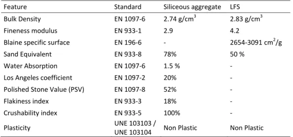
(7) 133. The LFS used in this research was provided by a Spanish company which produces carbon steel. 134. pipes by melting scrap in an Electric Arc Furnace and then refining it in a Ladle Furnace.. 135. The LFS, obtained after spontaneous cooling, is a grayish‐white powdery material, with a. 136. particle size of 0/2 mm. Its physical properties and chemical composition are detailed in tables. 137. 1 and 2, respectively.. 138. Table 1. Physical properties of the siliceous aggregate and the LFS Feature. Standard. Siliceous aggregate. LFS. Bulk Density. EN 1097‐6. 2.74 g/cm. 2.83 g/cm3. Fineness modulus. EN 933‐1. 2.9. 4.2. Blaine specific surface. EN 196‐6. ‐. 2654‐3091 cm2/g. Sand Equivalent. EN 933‐8. 78%. 50 %. Water Absorption. EN 1097‐6. 1.5 %. ‐. Los Angeles coefficient. EN 1097‐2. 20%. ‐. Polished Stone Value (PSV). EN 1097‐8. 52%. ‐. Flakiness index. EN 933‐3. 18%. ‐. Crushability index. EN 933‐5 UNE 103103 / UNE 103104. 100%. ‐. Non Plastic. Non Plastic. Plasticity. 139. 3. Table 2. Chemical composition of the LFS used. Component CaO wt.‐% 56.7. SiO2 17.7. MgO 9.6. Al2O3 6.6. Fe2O3 2.2. TiO2 0.3. SO3 0.9. CO2 1.3. Others 4.7. LOI 4.0. 140. The complete mineralogical and morphological microstructural characterization of this slag,. 141. labeled as slag E, can be found in previous papers of the research group of the Authors [15,. 142. 16]. It presents medium amounts of periclase and portlandite, calcium‐olivine silicates and. 143. reactive aluminates such as mayenite, as may be observed in figures 1a and 1b.. 144. 145. 146 7.
(8) 147. 148. 149. 150 M:Periclase F:Fluorite P:Portlandite O:Calcium‐Olivine C:Calcite My:Mayenite A:Aluminates J:Jasmundite K:Hydrated calcium aluminates. 151. Figure 1a. LFS Diffraction Pattern.. Figure 1b. LFS Scanning Electron Microscopy. 152. This research group also subjected this LFS to a potential expansion test in previous studies. 153. [15]. The main conclusion was that, although complying with the requirements of potential. 154. expansion after a week, according to ASTM‐2940 (<0.5%), delayed swelling registered higher. 155. values (>18%). This behavior leads us to advise caution, as previously noted, in the use of LFS.. 156. 2.3. Specimen preparation. 157. Each specimen was manufactured according to EN 12697‐35 [65] specifications on materials,. 158. preparation and mixing. Polymer‐modified bitumen was applied according to the. 159. manufacturer’s recommended temperatures: 160ºC for mixing and 155ºC for compaction.. 160. Specimens of 101.6 mm in diameter and approximately 63.5 mm in height were prepared for. 161. the Marshall compaction, by applying 50 blows on each face, as described in EN 12697‐30 [65].. 162. Binder draindown tests were conducted on uncompacted samples.. 163. 2.4. Mix‐design procedure. 164. In a preliminary phase of the research, two types of mixes were designed: a mixture named. 165. PA‐SC, made with the standard components (siliceous sand and cement as filler) and a mixture. 166. named PA‐LL, with the ladle furnace slag as both fine aggregate and filler.. 8.
(9) 167. The particle size distribution of the mixture was chosen for the grading envelope named PA‐11. 168. in the Spanish Standard PG‐3 [66], reflected in table 3. It is a porous asphalt mix, with a. 169. nominal maximum size of 11 mm and a thick mineral skeleton, with a large void ratio (>20%).. 170. Table 3. Grading envelope PA‐11 from Spanish Standard PG‐3 [66]. Sieve size (mm). 16. 11.2. 8. 4. 2. 0.5. 0.063. Mass percent passing. 100. 90‐100. 50‐70. 13‐27. 10‐17. 5‐12. 3‐6. 171. In this preliminary phase of the research, a series of initial tests were established to choose the. 172. optimum bitumen content (OBC). Some series of samples were manufactured with bitumen. 173. contents varying from 4.5% to 6%. Slight differences in particle distribution were. 174. accommodated to maintain the filler/asphalt ratio under the established limits.. 175. The choice of OBC was taken on the basis of the results of two tests: the Cantabro test, which. 176. provides information on minimum bitumen content, and the binder drainage test, which limits. 177. the maximum content.. 178. In the Cantabro test, each Marshall specimen is placed inside the Los Angeles abrasion drum. 179. without steel balls. Then, the drum is operated for 300 revolutions, at 30 revolutions/min, as. 180. described in EN 12697‐17 [65]. Particle loss, PL (%) is expressed as a ratio of the weight of the. 181. disintegrated particles, W1‐W2, over the initial weight of the specimen, W1.. 182. 100. /. (1). 183. The binder drainage or draindown test prescribed by EN 12697‐18 [65] consists in preparing a. 184. loose asphalt mixture sample at the designed asphalt binder content and then placing it in a. 185. perforated basket (see figure 2a.) in an oven at 170ºC for 3 hours; so that the mastic that flows. 186. through the perforations can be weighed, as shown in figure 2b.. 9.
(10) 187 188. Figure 2a. Binder drainage basket containing the asphalt mixture. 189. Figure 2b. Mastic flow from the basket after the test. 190. The percentage of the drained mastic to the original sample weight is referred to as its. 191. draindown value, D (%).. 192. 2.5. Testing program. 193. Volumetric properties, mechanical behavior, durability and moisture susceptibility were. 194. tested. Tests were conducted in triplicate on each mixture.. 195. 2.5.1. Volumetric properties. 196. For each sample, and prior to testing, the air void content (AVC) of the specimen was. 197. determined according to EN 12697‐8 [65], from the maximum density of the mixture. 198. (determined by the mathematical procedure defined in EN 12697‐5 [65]) and the bulk density. 199. (according to the geometrical procedure defined in EN 12697‐6 [65]).. 200. This procedure is essential to verify the success of the sample design and preparation and to. 201. establish the air void content of the mixtures, which is a key characteristic of the bituminous. 202. mix [67]. Samples had in all cases to be discarded, if not within a set range of values (21% ±. 203. 3%).. 204. The permeability coefficient (K) of the mixtures was also assessed, using the constant head. 205. permeameter, according to the vertical permeability test described in EN 12697‐19 [65].. 10.
(11) 206. 2.5.2. Mechanical behavior. 207. There is wide agreement over the critical parameter that determines the performance of. 208. mixtures with a high content of voids: resistance to raveling or abrasion [68]. The Cantabro. 209. test, as described in 2.4., is commonly used to evaluate resistance to wear and particle losses. 210. in porous asphalt mixtures, because of its better correlation with the performance and. 211. durability of such mixtures [69].. 212. Basic wear resistance of the mixtures, Basic Abrasion Loss (BAL), has to be determined by the. 213. Cantabro test, performed at 25ºC in accordance with Spanish regulation PG‐3 [66]. However,. 214. the drum was not placed in a thermostatic room and the actual temperature at which each. 215. test took place was recorded. Nevertheless, particle losses of specimens at lower. 216. temperatures (15‐20 °C) are known to be higher than those obtained at 25 °C [70], so the. 217. results are expected to be on the safe side.. 218. Indirect Tensile Strength (ITS) was tested as described in EN 12697‐23 [65], where the. 219. cylindrical cross‐section of the specimen is subjected to diametric compressive loading until. 220. breakage. As in the Marshall test, the load is applied at a constant strain rate of 50 ± 2. 221. mm/min.. 222. The ITS (N/mm2) is obtained from the maximum tensile strength calculation, based on the. 223. maximum load applied at the moment of breakage, P (N) and the dimensions of the specimen,. 224. h (height) and R (radius), (mm).. 225. 226. /. (2). 2.5.3. Durability. 227. A frequently evaluated feature in the literature is resistance to wear abrasion on aged. 228. specimens: Aged Abrasion Loss (AAL). The accelerated aging process is regulated by the ASTM. 229. D‐7064 [71] and consists in keeping the specimens for 7 days in a forced draft oven at 60°C. 11.
(12) 230. They are then conditioned at the test temperature for 4 hours, after which the Cantabro test is. 231. performed.. 232. Likewise, to investigate the potential effect of binder aging on the cohesion loss of the. 233. mixtures, the samples were subjected to controlled aging, in which they were held in a. 234. regulated environment (humid chamber 23°C and 96% humidity) for 6 months. Thereafter,. 235. their Long term performance (LTP) in terms of wear resistance was evaluated and compared. 236. to the fresh samples.. 237. Bituminous mixtures stiffen at low temperatures and are more susceptible to brittle fracture. 238. and cracking. Although not a regulatory requirement, a mechanical test after conditioning the. 239. samples at low temperatures is recommended. Sample conditioning was done by placing the. 240. specimens in a freezing temperature of 1ºC for 24h, after which their particle loss was tested,. 241. with the Cold Abrasion Loss (CAL) test, as described by Álvarez et al. [69].. 242. The former three mean durability results are expressed, both in absolute and relative terms. 243. with the fresh test results (PLb, Particle Loss in basic conditions), through “loss increment. 244. indexes”: Aged Abrasion Loss index (AAL index), Long Term Performance index (LTP index) and. 245. Cold Abrasion Loss index (CAL index), which are defined as follows:. 246. /. (3). 247. /. (4). 248. /. (5). 249. 2.5.4. Moisture susceptibility. 250. Moisture produces the loss of adhesion between the asphalt binder and the aggregate surface,. 251. and accelerates deterioration in the form of potholes, cracking and raveling [72].. 12.
(13) 252. Moisture susceptibility or resistance to moisture damage in the PA mixes was assessed. 253. through two approaches: retained tensile strength or the tensile strength ratio (TSR) as. 254. specified by EN 12697‐12 [65], and wet abrasion loss (WAL), in accordance with Spanish. 255. regulation NLT‐362/92. In both cases, six Marshall specimens were divided into two groups:. 256. the control subset, which remains dry at room temperature, and the conditioned subset,. 257. which is saturated and submerged in hot water for a period of time (40ºC for about 72h in the. 258. TSR and 60ºC for 24h in the WAL). Both performance indexes are the result of comparing the. 259. conditioned results (ITSw, PLw) against the dry results (ITSd, PLd).. 260. %. 100. / /. 261. (6) (7). 262. In this case, the standard procedure was followed, except for sample saturation, as no vacuum. 263. machine is available at the laboratory facilities. Nonetheless, non‐saturation of voids through a. 264. vacuum machine is common in research on porous mixtures [73], because their high content. 265. of connected voids fill with water when left submerged in water [74]. Other authors maintain. 266. that this procedure is designed for bituminous concrete and is too aggressive for mixtures with. 267. a high void content, so they propose alternative non‐saturation procedures [75].. 268. 3. Results and discussion. 269. 3.1. Mix design. 270. Table 4 shows the gradation and composition of the bituminous mixtures and the results from. 271. the tests conducted in this preliminary phase.. 272. 273. 13.
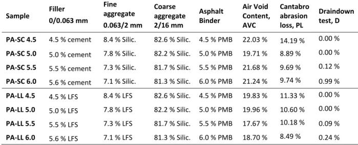
(14) 274. Table 4. Mix design results Sample. Filler 0/0.063 mm. Fine aggregate 0.063/2 mm. Coarse aggregate 2/16 mm. Asphalt Binder. Air Void Content, AVC. Cantabro abrasion loss, PL. Draindown test, D. PA‐SC 4.5. 4.5 % cement. 8.4 % Silic.. 82.6 % Silic.. 4.5 % PMB. 22.03 %. 14.19 %. 0.00 %. PA‐SC 5.0. 5.0 % cement. 7.8 % Silic.. 82.2 % Silic.. 5.0 % PMB. 19.71 %. 8.89 %. 0.00 %. PA‐SC 5.5. 5.5 % cement. 7.3 % Silic.. 81.7 % Silic.. 5.5 % PMB. 21.68 %. 9.69 %. 0.12 %. PA‐SC 6.0. 5.6 % cement. 7.1 % Silic.. 81.3 % Silic.. 6.0 % PMB. 21.24 %. 9.74 %. 0.99 %. PA‐LL 4.5. 4.5 % LFS. 8.4 % LFS. 82.6 % Silic.. 4.5 % PMB. 19.83 %. 11.33 %. 0.00 %. PA‐LL 5.0. 5.0 % LFS. 7.8 % LFS. 82.2 % Silic.. 5.0 % PMB. 19.96 %. 10.60 %. 0.00 %. PA‐LL 5.5. 5.5 % LFS. 7.3 % LFS. 81.7 % Silic.. 5.5 % PMB. 17.67 %. 10.18 %. 0.09 %. PA‐LL 6.0. 5.6 % LFS. 7.1 % LFS. 81.3 % Silic.. 6.0 % PMB. 18.70 %. 8.49 %. 0.24 %. 275. As shown in table 4, particle losses tend to increase as the binder content decreases, because. 276. the bitumen film that covers the aggregates protects them from wear and enhances cohesion. 277. and adhesion. Although the abrasion loss results were excellent for all the tested mixes, the. 278. performance of the mixtures designed with 4.5% binder was perceivably worse.. 279. Moreover, binder drainage usually occurs in asphalt mixtures lacking fine aggregate and filler. 280. that maintain the binder in place, so as to create appropriate mastics. In general, drainage. 281. control leads to an upper limitation of the bitumen content. Spanish regulations [66] are very. 282. strict and allow no draindown, hence binder contents over 5% must be discarded.. 283. Finally, given the similar behavior of the two types of mixtures, it was decided to adopt the. 284. same particle size and the same OBC. Samples containing 5% of bitumen were considered to. 285. be balanced in durability, strength and potential draindown.. 286. Additional information can be extracted from the draindown test. First of all, the test. 287. demonstrates that LFS functions properly as filler, presenting good adhesion with the bitumen. 288. and forming quality mastic. Otherwise, binder drainage would occur for all bitumen contents. 289. and not only for the higher ones. Secondly, as may be observed in table 4, it appears that for. 290. high bitumen contents, the samples made with LFS produced less binder drainage than the. 14.
(15) 291. control mixtures, which suggests that LFS has higher asphalt absorption than the conventional. 292. components. This may be related to the higher porosity or rougher texture of the slag.. 293. In the following phase of the research, three types of mixtures were manufactured with the. 294. selected particle size distribution and OBC as described in table 5. Their components varied to. 295. observe the influence of the LFS in the mix behavior. PA‐SL mix incorporated the LFS only as. 296. filler, while the PA‐LL used it in its whole particle size, as filler and fine aggregate. Their results. 297. will always be compared with the control mix, PA‐SC.. 298. Table 5. Final mix design. Content. 299 300. Materials used PA‐SC. PA‐SL. PA‐LL. Coarse aggregate. 82.2 %. Siliceous. Siliceous. Siliceous. Fine aggregate. 7.8 %. Siliceous. Siliceous. LFS. Filler. 5.0 %. Cement. LFS. LFS. Binder. 5.0 %. PMB 45/80‐60. PMB 45/80‐60. PMB 45/80‐60. 3.2.. Volumetric properties. The average volumetric properties of all the specimens that were tested appear in table 6.. 301. Table 6. Volumetric properties PA‐SC. PA‐SL. PA‐LL. 3. Bulk density (g/cm ) EN 12697‐6. 2.000. 1.999. 1.986. Maximum density (g/cm3) EN 12697‐5. 2.537. 2.531. 2.536. Air voids (%) EN 12697‐8. 21.1%. Permeability (cm/s) EN 12697‐19. 9.07 ∙ 10. 21.0% ‐2. 9.01 ∙ 10. 21.7% ‐2. 9.04 ∙ 10‐2. 302. The calculated maximum density of the three types of mixture is similar, as the siliceous. 303. aggregate and the LFS share very similar densities.. 304. A slight increase in the void content of the mixtures may be inferred when introducing the LFS. 305. in the range of the fine material. This increase may be due to the superior angularity of LFS 15.
(16) 306. compared to the siliceous sands. It should be remembered that the siliceous sands are. 307. particularly rounded fine materials, used sometimes in bituminous mixtures to improve their. 308. compaction.. 309. Some studies, in relation to the use of black slags (EAFS, BOFS) in the manufacture of. 310. bituminous mixtures, reported that the void content of the mixes increased, because of the. 311. greater sharpness of the slag particles. This increment was noted even when the slag was only. 312. used as fine aggregate [58].. 313. Permeability tests yielded very similar mean results, as expected with similar air void contents,. 314. demonstrating that the introduction of LFS has no effect on the permeability of the mixtures.. 315. The values provided an acceptable and durable permeable behavior.. 316. 3.3.. Mechanical behavior. 317. Wear resistance of both the PA‐SL and the control mixtures was very similar, as shown in table. 318. 7. In fact, a slight improvement could be detected in the PA‐SL mixtures, although that might. 319. also be attributed to the higher test temperature, which was favorable [70]. However, when. 320. using LFS as fine and filler replacement (PA‐LL mixes), an increase in particle loss was. 321. noticeable. These losses might be due to the higher bitumen absorption of the LFS detected in. 322. the “binder drainage test”, which would produce thinness in the binder film that covers the. 323. particles, decreasing their resistance to raveling.. 324. Table 7. Mechanical behavior. Basic Abrasion Loss (BAL). Indirect Tensile Strength (ITS). PA‐SC. PA‐SL. PA‐LL. Void Content (%). 19.79. 21.92. 19.97. Test Temperature (ºC). 20. 25. 20. Particle loss, PLb (%). 8.06. 7.12. 10.57. Void Content (%). 22.10. 18.53. 22.30. Maximum load (N). 12.96. 12.95. 13.53. ITS (N/mm2). 1.26. 1.30. 1.31. 16.
(17) 325. In any event, every mixture greatly exceeded the standard requirements, which have to be. 326. under 20% of Particle Loss, as required by the Spanish standards [66] for the most demanding. 327. applications. Regulations in other countries required values from 15% to 30% of maximum. 328. loss, depending on the type of traffic and the test temperature [76].. 329. The indirect tensile strength values were very good. A good cohesion of the mixtures may be. 330. inferred as well as high resistance to cracking and fine performance under shear stress.. 331. Furthermore, the results were very close in the different mixtures; hence, the introduction of. 332. LFS as filler or fines will neither worsen the performance of pavements under tensile stress nor. 333. produce a loss of cohesion in the bituminous mix.. 334. 3.4.. Durability. 335. The average results of the different durability tests made to the asphalt mixes appear in table. 336. 8, below.. 337. Table 8. Mixture Durability. Aged Abrasion Loss (AAL). Long‐Term Performance (LTP). Cold Abrasion Loss (CAL). PA‐SC. PA‐SL. PA‐LL. Void Content (%). 19.14. 21.62. 21.06. Particle loss, PLa (%). 12.07. 8.83. 13.06. AAL Index. 1.50. 1.24. 1.24. Void Content (%). 21.37. 20.17. 23.58. Particle loss, PLl (%). 8.52. 8.05. 10.44. LTP Index. 1.06. 1.13. 0.99. Void Content (%). 22.70. 20.62. 22.7. Particle loss, PLc (%). 23.84. 17.90. 26.57. CAL Index. 2.96. 2.51. 2.51. 338. Following the fresh trend, aged abrasion loss of the samples made with LFS as filler (PA‐SL). 339. were the best, while the results of the PA‐LL mixes were slightly worse than those of the. 340. conventional components (PA‐SC). 17.
(18) 341. Standard ASTM D‐7064 [71] imposes a particle‐loss limit of 50% on the values of individual. 342. samples and a limit of 30% on the overall average results. All of the specimens that were. 343. tested more than complied with those requirements.. 344. It was also observed that the effect of time on specimen wear resistance (Long‐Term. 345. Performance) was practically non‐existent. The behavior of the specimens after six months. 346. was very similar to the behavior of the fresh samples, such that the aging of the designed. 347. pavement was successful.. 348. Again following the fresh trend, the samples with LFS as filler showed the best low‐. 349. temperature performance (Cold Abrasion Loss), followed by the PA‐SC and the PA‐LL mixes.. 350. However, regarding the loss increment index under cold conditions, it may be noted that. 351. introducing LFS as filler improves the thermal susceptibility of the mixtures.. 352. 3.5.. Moisture susceptibility. 353. In terms of the Tensile Strength Ratio of the samples, the performance of all three types of. 354. mixes was similar, as can be observed in Figure 3a. Regulations in the U.S. require TSR values. 355. of between 70% and 80%, depending on each State Administration [71, 75], so the mixtures. 356. may not comply with some of those requirements.. 357. Anyway, some researchers consider that this method may not be appropriate to evaluate. 358. moisture sensitivity in high air void content mixtures and propose a search for an alternative. 359. approach [61, 75], such as the Wet Abrasion Loss, described below.. 360. Beyond these preliminary considerations, it may be observed that the mixtures incorporating. 361. LF slag provide results that are in line with those of the standard mixture. This happens in both. 362. indirect tensile strength after wet conditioning (ITSw), as in the tensile strength ratio (TSR).. 363. Therefore, it may at the very least be stated that the slag in no way worsens the performance. 18.
(19) 364. of materials that are commonly used for manufacturing quality porous asphalt (cement and. 365. silica).. 366. In addition, the resistance of the slag mixes to raveling under wet conditions (Wet Abrasion. 367. Loss) was better than the performance of the control mix, both in absolute terms (PLw) and in. 368. comparison with the fresh samples (WAL index), as reflected in figure 3b. In fact, water. 369. sensitivity gradually improved with the incorporation of slag. Unlike with the TSR, each mix. 370. exceeded the requirements of PLw, which should be below 30%.. 371 372. Figure 3a. Moisture susceptibility through TSR. 373. Figure 3b. Moisture susceptibility through WAL. 374. From the results of this test, it could be inferred that the LFS showed good affinity with the. 375. binder, forming quality mastic, and giving good cohesion to the mix. This could be due to the. 376. basicity of the slag, which has better adhesion with the binder than the silica, which is an. 377. “acid” aggregate, forming a more cohesive mixture. Furthermore, the slag texture is rougher,. 378. which also favors the passive adherence of bitumen.. 379. 4. Conclusions. 380. 1. Mix design and OBC in slag mixes can be assimilated to the control mixes. The void. 381. content of the mixtures with LFS sand was slightly higher, which may be due to the. 19.
(20) 382. superior angularity of the slag. Mean permeability results were also very close to those. 383. of the control mixes.. 384. 2. The binder drainage test demonstrated that the LFS works properly as filler, presenting. 385. good adhesion with the bitumen and forming good quality mastic. It was also noted. 386. that white slag had superior bitumen absorption than the conventional materials.. 387. 3. The mechanical behavior of the mixes (abrasion, tensile strength) was excellent for. 388. every mixture designed, which enables these mixtures to be used even in the most. 389. demanding applications. Mixtures manufactured with slag sand showed a slightly. 390. worse performance, which could be attributed to the higher bitumen absorption of the. 391. slag.. 392 393. 4. Aging produced similar effects on every mixture, far exceeding the regulatory recommendations.. 394. 5. Thermal susceptibility of the mixtures improved with the incorporation of ladle slag.. 395. 6. Moisture sensitivity in terms of TSR hardly met the regulatory requirements, although. 396. this may not be significant for the porous asphalt mixes. Water resistance evaluated by. 397. the Wet Abrasion Loss exceeded the prescriptions and showed a good cohesive. 398. performance that, in fact, increased with the incorporation of slag. The rougher. 399. texture of the slag and its better adhesion to the binder are favorable for the moisture. 400. susceptibility of the mixes.. 401. These results will hopefully encourage further research on the viability of replacing sand and. 402. cement with ladle furnace slag in porous asphalt mixtures.. 403. Acknowledgments. 404. Our gratitude to the Spanish Ministry of Economy and Competitiveness (MINECO) and FEDER. 405. Funds for their financial support through Project BlueCons: BIA2014‐55576‐C2‐1‐R.. 406 20.
(21) 407. References. 408 409. [1] Akinmusuru JO. Potential beneficial uses of steel slag wastes for civil engineering purposes. Resources, Conservation and Recycling. 1991;5(1):73‐80.. 410. [2] Geiseler J. Use of steelworks slag in Europe. Waste Management. 1996;16(1‐3):59‐63.. 411 412. [3] Motz H, Geiseler J. Products of steel slags an opportunity to save natural resources. Waste Management. 2001;21(3):285‐93.. 413 414. [4] Pioro LS, Pioro IL. Reprocessing of metallurgical slag into materials for the building industry. Waste Management. 2004;24(4):371‐9.. 415 416. [5] Dippenaar R. Industrial uses of slag (the use and re‐use of iron and steelmaking slags). Ironmaking and Steelmaking. 2005;32(1):35‐46.. 417 418. [6] Tsakiridis PE, Papadimitriou GD, Tsivilis S, Koroneos C. Utilization of steel slag for Portland cement clinker production. Journal of Hazardous Materials. 2008;152(2):805‐11.. 419 420. [7] Wang G, Wang Y, Gao Z. Use of steel slag as a granular material: Volume expansion prediction and usability criteria. Journal of Hazardous Materials. 2010;184(1‐3):555‐60.. 421 422 423. [8] Memoli F, Mapelli C, Guzzon M. Recycling of ladle slag in the EAF: A way to improve environmental conditions and reduce variable costs in steel plants. Iron and Steel Technology. 2007;4(2):68‐76.. 424 425. [9] Porisiensi S. Recycling of ladle slag and spent refractories by injection into an EAF. Iron and Steel Technology. 2004;1(6):63‐6.. 426. [10] Tsubone A. Direct recycling of the reducing slag in EAF. SEAISI Q. 2006;35(4):32‐8.. 427 428. [11] Lee TS, Choi IS, Song WY. The technology of recycling ladle slag. Stahl und Eisen. 2003;123(12):113‐7.. 429 430. [12] Dahlin A, Tilliander A, Eriksson J, Jönsson PG. Influence of ladle slag additions on BOF process performance. Ironmaking and Steelmaking. 2012;39(5):378‐85.. 431 432. [13] Adolfsson D, Engström F, Robinson R, Björkman B. Cementitious phases in ladle slag. Steel Res Int. 2011;82(4):398‐403.. 433 434. [14] Shi C. Characteristics and cementitious properties of ladle slag fines from steel production. Cement and Concrete Research. 2002;32(3):459‐62.. 435 436 437. [15] Ortega‐López V, Manso JM, Cuesta II, González JJ. The long‐term accelerated expansion of various ladle‐furnace basic slags and their soil‐stabilization applications. Construction and Building Materials. 2014;68:455‐64.. 438 439. [16] Manso JM, Ortega‐López V, Polanco JA, Setién J. The use of ladle furnace slag in soil stabilization. Construction and Building Materials. 2013;40:126‐34.. 440 441. [17] Richardson IG, Cabrera JG. The nature of C‐S‐H in model slag cements. Cement and concrete composites. 2000;22(4):259‐66.. 442 443. [18] Akin Altun I, Yilmaz I. Study on steel furnace slags with high MgO as additive in Portland cement. Cement and Concrete Research. 2002;32(8):1247‐9.. 444 445. [19] CEDEX. Escorias de acería de horno de arco eléctrico. Ficha técnica. Catálogo de residuos utilizables en construcción2013.. 446 447. [20] Manso JM, Rodriguez A, Aragón A, Gonzalez JJ. The durability of masonry mortars made with ladle furnace slag. Construction and Building Materials. 2011;25(8):3508‐19.. 448 449. [21] Faraone N, Tonello G, Furlani E, Maschio S. Steelmaking slag as aggregate for mortars: Effects of particle dimension on compression strength. Chemosphere. 2009;77(8):1152‐6.. 450 451. [22] Papayianni I, Anastasiou E. Effect of granulometry on cementitious properties of ladle furnace slag. Cement and Concrete Composites. 2012;34(3):400‐7.. 21.
(22) 452 453 454. [23] Rodriguez A, Manso JM, Aragón A, Gonzalez JJ. Strength and workability of masonry mortars manufactured with ladle furnace slag. Resources, Conservation and Recycling. 2009;53(11):645‐51.. 455 456. [24] Santamaría A, Rojí E, Skaf M, Marcos I, González JJ. The use of steelmaking slags and fly ash in structural mortars. Construction and Building Materials. 2016;106:364‐73.. 457 458. [25] Polanco JA, Manso JM, Setién J, González JJ. Strength and durability of concrete made with electric steelmaking slag. ACI Materials Journal. 2011;108(2):196‐203.. 459 460. [26] Manso JM, Hernández D, Losáñez MM, González JJ. Design and elaboration of concrete mixtures using steelmaking slags. ACI Materials Journal. 2011;108(6):673‐81.. 461 462. [27] Papayianni I, Anastasiou E. Production of high‐strength concrete using high volume of industrial by‐products. Construction and Building Materials. 2010;24(8):1412‐7.. 463 464 465. [28] Anagnostopoulos N, Sideris KK, Georgiadis A. Mechanical characteristics of self‐ compacting concretes with different filler materials, exposed to elevated temperatures. Materials and Structures/Materiaux et Constructions. 2009;42(10):1393‐405.. 466 467 468. [29] Anastasiou EK, Papayianni I, Papachristoforou M. Behavior of self compacting concrete containing ladle furnace slag and steel fiber reinforcement. Materials and Design. 2014;59:454‐ 60.. 469 470 471. [30] Montenegro JM, Celemín‐Matachana M, Cañizal J, Setién J. Ladle furnace slag in the construction of embankments: Expansive behavior. Journal of Materials in Civil Engineering. 2013;25(8):972‐9.. 472 473 474. [31] Sun DD, Tay JH, Cheong HK, Leung DLK, Qian G. Recovery of heavy metals and stabilization of spent hydrotreating catalyst using a glass‐ceramic matrix. Journal of Hazardous Materials. 2001;87(1‐3):213‐23.. 475 476. [32] Radenović A, Malina J, Sofilić T. Characterization of ladle furnace slag from carbon steel production as a potential adsorbent. Adv Mater Sci Eng. 2013;2013.. 477 478. [33] Gahan CS, Cunha ML, Sandström Å. Comparative study on different steel slags as neutralising agent in bioleaching. Hydrometallurgy. 2009;95(3‐4):190‐7.. 479 480 481. [34] Proctor DM, Fehling KA, Shay EC, Wittenborn JL, J.J. G, Avent C. Physical and chemical characteristics of blast furnace, basic oxygen furnace and electric arc furnace steel industry slag. Environ Sci Technol. 2000;34(8):1576‐82.. 482 483. [35] Herrmann I, Andreas L, Diener S, Lind L. Steel slag used in landfill cover liners: Laboratory and field tests. Waste Management and Research. 2010;28(12):1114‐21.. 484 485. [36] Akbulut H, Gürer C. Use of aggregates produced from marble quarry waste in asphalt pavements. Building and Environment. 2007;42(5):1921‐30.. 486 487. [37] Karakuş A. Investigating on possible use of Diyarbakir basalt waste in Stone Mastic Asphalt. Construction and Building Materials. 2011;25(8):3502‐7.. 488 489 490. [38] Velasquez R, Turos M, Moon KH, Zanko L, Marasteanu M. Using recycled taconite as alternative aggregate in asphalt pavements. Construction and Building Materials. 2009;23(9):3070‐8.. 491 492. [39] Bakis R, Koyuncu H, Demirbas A. An investigation of waste foundry sand in asphalt concrete mixtures. Waste Management and Research. 2006;24(3):269‐74.. 493 494 495. [40] Pasetto M, Baldo N. Laboratory investigation on foamed bitumen bound mixtures made with steel slag, foundry sand, bottom ash and reclaimed asphalt pavement. Road Materials and Pavement Design. 2012;13(4):691‐712.. 496 497. [41] Churchill EV, Amirkhanian SN. Coal ash utilization in asphalt concrete mixtures. Journal of Materials in Civil Engineering. 1999;11(4):295‐301.. 498 499. [42] Tapkin S. Mechanical evaluation of asphalt‐aggregate mixtures prepared with fly ash as a filler replacement. Canadian Journal of Civil Engineering. 2008;35(1):27‐40.. 22.
(23) 500 501 502. [43] Huang B, Shu X, Dong Q, Shen J. Laboratory evaluation of moisture susceptibility of hot‐ mix asphalt containing cementitious fillers. Journal of Materials in Civil Engineering. 2010;22(7):667‐73.. 503 504 505. [44] Xue Y, Hou H, Zhu S, Zha J. Utilization of municipal solid waste incineration ash in stone mastic asphalt mixture: Pavement performance and environmental impact. Construction and Building Materials. 2009;23(2):989‐96.. 506 507 508. [45] Melotti R, Santagata E, Bassani M, Salvo M, Rizzo S. A preliminary investigation into the physical and chemical properties of biomass ashes used as aggregate fillers for bituminous mixtures. Waste Management. 2013;33(9):1906‐17.. 509 510 511 512 513. [46] An J, Golestani B, Nam BH, Lee JL. Sustainable utilization of MSWI bottom ash as road construction materials, part I: Physical and mechanical evaluation. In: Harvey JT, Chou KF, editors. 2015 International Airfield and Highway Pavements Conference: Innovative and Cost‐ Effective Pavements for a Sustainable Future: American Society of Civil Engineers (ASCE); 2015. p. 225‐35.. 514 515. [47] Taha R, Al‐Rawas A, Al‐Harthy A, Qatan A. Use of cement bypass dust as filler in asphalt concrete mixtures. Journal of Materials in Civil Engineering. 2002;14(4):338‐43.. 516 517. [48] Disfani MM, Arulrajah A, Bo MW, Sivakugan N. Environmental risks of using recycled crushed glass in road applications. J Clean Prod. 2012;20(1):170‐9.. 518 519. [49] Arabani M. Effect of glass cullet on the improvement of the dynamic behaviour of asphalt concrete. Construction and Building Materials. 2011;25(3):1181‐5.. 520 521. [50] Su N, Chen JS. Engineering properties of asphalt concrete made with recycled glass. Resources, Conservation and Recycling. 2002;35(4):259‐74.. 522 523. [51] Wong YD, Sun DD, Lai D. Value‐added utilisation of recycled concrete in hot‐mix asphalt. Waste Management. 2007;27(2):294‐301.. 524 525. [52] Chen M, Lin J, Wu S. Potential of recycled fine aggregates powder as filler in asphalt mixture. Construction and Building Materials. 2011;25(10):3909‐14.. 526 527 528. [53] Huang B, Dong Q, Burdette EG. Laboratory evaluation of incorporating waste ceramic materials into Portland cement and asphaltic concrete. Construction and Building Materials. 2009;23(12):3451‐6.. 529 530. [54] Chen MZ, Lin JT, Wu SP, Liu CH. Utilization of recycled brick powder as alternative filler in asphalt mixture. Construction and Building Materials. 2011;25(4):1532‐6.. 531 532 533 534. [55] Golestani B, Maherinia H, Nam BH, Behzadan A. Investigation on the effects of recycled asphalt shingle as an additive to hot‐mix asphalt. In: Harvey JT, Chou KF, editors. 2015 International Airfield and Highway Pavements Conference: Innovative and Cost‐Effective Pavements for a Sustainable Future: American Society of Civil Engineers (ASCE); 2015. p. 9‐18.. 535 536. [56] Kandhal PS, Hoffman GL. Evaluation of steel slag fine aggregate in hot‐mix asphalt mixtures. 1997. p. 28‐36.. 537 538. [57] Arabani M, Azarhoosh AR. The effect of recycled concrete aggregate and steel slag on the dynamic properties of asphalt mixtures. Construction and Building Materials. 2012;35:1‐7.. 539 540. [58] Bagampadde U, Al‐Abdul Wahhab HI, Aiban SA. Optimization of steel slag aggregates for bituminous mixes in Saudi Arabia. Journal of Materials in Civil Engineering. 1999;11(1):30‐5.. 541 542 543. [59] Pasetto M, Baldo N. Rutting resistance of Stone Mastic Asphalts with steel slag and Coal Ash. 3rd International Conference on Transportation Infrastructure, ICTI 2014. Pisa: shers; 2014. p. 31‐42.. 544 545 546. [60] Pasetto M, Baldo N. Fatigue performance and stiffness properties of Stone Mastic Asphalts with steel slag and coal ash. 12th International Conference on Asphalt Pavements, ISAP 2014. Raleigh, NC: Taylor and Francis ‐ Balkema; 2014. p. 881‐9.. 547 548. [61] Alvarez AE, Martin AE, Estakhri C. A review of mix design and evaluation research for permeable friction course mixtures. Construction and Building Materials. 2011;25(3):1159‐66.. 23.
(24) 549 550. [62] Eck BJ, Winston RJ, Hunt WF, Barrett ME. Water quality of drainage from permeable friction course. Journal of Environmental Engineering. 2012;138(2):174‐81.. 551 552. [63] Ongel A, Kohler E, Harvey J. Principal components regression of onboard sound intensity levels. J Transp Eng. 2008;134(11):459‐66.. 553 554 555. [64] Kowalski KJ, McDaniel RS, Shah A, Olek J. Long‐term monitoring of noise and frictional properties of three pavements: Dense‐graded asphalt, stone matrix asphalt, and porous friction course. Transportation Research Record2009. p. 12‐9.. 556 557. [65] EN Euronorm. Rue de Stassart, 36. Belgium–1050 Brussels.: European Committee for Standardization.. 558 559 560. [66] Pliego de Prescripciones Técnicas Generales para Obras de Carreteras y Puentes, PG‐3 (General Technical Specifications in Road Construction) Madrid: Spanish Ministry of Public Works.. 561 562. [67] Mansour TN, Putman BJ. Influence of aggregate gradation on the performance properties of porous asphalt mixtures. Journal of Materials in Civil Engineering. 2013;25(2):281‐8.. 563 564 565. [68] Mallick RB, Cooley L.A, Jr. Design, construction, and performance of new‐generation open‐ graded friction courses. Proceedings of the Association of Asphalt Paving Technologists. 2000;69:391‐423.. 566 567. [69] Alvarez AE, Epps‐Martin A, Estakhri C, Izzo R. Evaluation of durability tests for permeable friction course mixtures. International Journal of Pavement Engineering. 2010;11(1):49‐60.. 568 569 570. [70] Hamzah MO, Hasan MRM, Van De Ven M, Yahaya AS. The effects of initial conditioning and ambient temperatures on abrasion loss and temperature change of porous asphalt. Construction and Building Materials. 2012;29:108‐13.. 571 572 573. [71] Standard practice for Open Graded Friction Course (OGFC) mix design. West Conshohocken, P.A.: American Society for Testing and Materials (ASTM). Annual Book of ASTM Standards; 2004.. 574 575 576 577. [72] TRB. Committee on Bituminous–Aggregate Combinations to Meet Surface Requirements. Moisture Sensitivity of Asphalt Pavements. National Seminar on Moisture Sensitivity of Asphalt Pavements. San Diego, California, U.S.: Transportation Research Board Miscellaneous Report; 2003.. 578 579 580. [73] Suresha SN, Varghese G, Shankar AUR. A comparative study on properties of porous friction course mixes with neat bitumen and modified binders. Construction and Building Materials. 2009;23(3):1211‐7.. 581 582. [74] Lyons KR, Putman BJ. Laboratory evaluation of stabilizing methods for porous asphalt mixtures. Construction and Building Materials. 2013;49:772‐80.. 583 584. [75] Wang Y, Wang G. Improvement of porous pavement. Final Report to US Green Building Council East Carolina University, Greenville, NC2011.. 585 586. [76] Fazleen Hanim Ahmad Kamar JNS. Design of porous asphalt mixture to performance related criteria. Malaysia: Public Works Department, Malaysia; 2008.. 587 588. 24.
(25)
Figure
Documento similar
In order to obtain SSS-FA mixes appropriate for use as cement substitutes in the manufacture of SCC, an initial study of the flexural and compressive strength of pastes
In the previous sections we have shown how astronomical alignments and solar hierophanies – with a common interest in the solstices − were substantiated in the
influence of these parameters on the size and distribution of Te inclusions, deep defects, optical and electrical properties of CdZnTe detectors. In the fourth chapter, the effect
Document management - a key technology for the construction industry, In: Information and Communications Technology (ICT) in the Practice of Building and Civil
b) Muy cerca de allí, en un lugar algo más urbanizado, quizás con una estructura arquitectónica 44 , debía estar el Ninfeo, relacionado con las aguas y las fuentes 45
This study employs a test protocol based on a 3-point bending DMA (Dynamic Mechanical An- alyzer) configuration to assess the influence of the type of filler and the bitumen
In most cases, simplified assumptions made in the preliminary considerations (pre- emptive yielding of steel, concrete and steel failure in unconfined and confined
After the construction of the different road sections, cores were taken at different periods of their service life (up to 63 months) and they were tested in the laboratory in order
