Development of a simulation tool for the economic optimization of an extraction plant for vegetable substrates using supercritical CO2
142
0
0
Texto completo
(2) PONTIFICIA UNIVERSIDAD CATOLICA DE CHILE ESCUELA DE INGENIERIA. DEVELOPMENT OF A SIMULATION TOOL FOR THE ECONOMIC OPTIMIZATION OF AN EXTRACTION PLANT FOR VEGETABLE SUBSTRATES USING SUPERCRITICAL CO2. GONZALO ALEXIS NÚÑEZ MONTOYA. Members of the Committee: JOSÉ M. DEL VALLE LLADSER CLAUDIO GELMI WESTON HÉCTOR JORQUERA GONZÁLEZ JULIO ROMERO FIGUEROA RUDOLF EGGERS CRISTIAN VIAL EDWARDS Thesis submitted CRISTIÁN VIALtoE.the Office of Research and Graduate Studies in partial fulfillment of the requirements for the Degree of Doctor in Engineering Sciences Santiago de Chile, (April, 2013).
(3) Dedicated to Daniela and Javiera, for all their love and support along all these years, and to my soon to be born daughter. ii.
(4) ACKNOWLEDGEMENTS First of all, I would like to thank my wife for her constant support during all these years. It would not have been possible to complete my work without your encouragement, understanding, friendship, and love. I sincerely acknowledge to my advisor, Dr. José Manuel del Valle. Thank you so much for all your help and fruitful discussions. But also I want to thank you for this life experience where I have learnt a lot of things such as researching, teaching, and tutorship, and you had been an integral part of all of those things. I thank to the members of my committee for their suggestions to improve this manuscript. I specially thank to Dr. Claudio Gelmi for all our discussions, good conversations, and for sharing your programming ideas for the development of my simulation tool. Thank you so much to everyone who helps me during my doctoral internship in Technische Universität Hamburg-Harburg (TUHH). In special I thank to Dr.-Ing. Rudolf Eggers for welcoming me into his research group, to Dr.-Ing. Philip Jäeger for his friendship and support, and to Mr. Florian Meyer for his friendship and invaluable help in my experimental work. I am very grateful with all my colleagues and friends in the Prof. del Valle’s research group: Karina Araus, Lorena Mödinger, Raúl Aravena, Fabián Reyes, Arturo Bejarano, Andrea Reveco, Eduardo Richter, Sofía Andrighetti, Caroline Sielfeld, and Soledad Murias. Also, I thank to Juan Carlos Germain for his previous work in modeling which it was my starting point in my simulations. Finally, I especially thank to my friend Freddy Urrego for sharing this wonderful road, plenty of learning and knowledge. I thank to the people that work or worked at Departamento de Ingeniería Química y Bioprocesos that in one way or another has helped or supported me during all of these years: Hilda Agurto, Rosa Araya, Gladys Barraza, Ricardo Cayupe, Ulises Lazo, Karina Rojas, Jakeline Salvatierra, and María Inés Valdebenito. iii.
(5) Finally, I really appreciate the help of the Chilean scientific agency CONICYT for funding both doctoral program with fellowship Beca de Doctorado and doctoral internship with Becas Chile.. iv.
(6) GENERAL INDEX Pág. DEDICATORY ................................................................................................................. ii ACKNOWLEDGEMENTS .............................................................................................iii TABLES INDEX ...........................................................................................................viii FIGURES INDEX ............................................................................................................. x RESUMEN ........................................................................................................... xiv ABSTRACT ......................................................................................................... xvi LIST OF PAPERS............................................................................................................. 1 1. INTRODUCTION...................................................................................................... 2 1.1 Supercritical fluid extraction of solid substrates with CO2 ............................. 3 1.2 Scaling-up of the supercritical CO2 extraction process ................................... 5 1.3 Costs in a supercritical CO2 extraction process .............................................. 7 1.4 Hypothesis ....................................................................................................... 9 1.5 Objectives ...................................................................................................... 10 2. SIMULATION. OF. A. SUPERCRITICAL. CARBON. DIOXIDE. EXTRACTION PLANT WITH THREE EXTRACTION VESSELS .................. 11 2.1 Introduction ................................................................................................... 11 2.2 Model development for a multi-vessel SCFE plant ...................................... 14 2.2.1 The problem of SCFE plants with three extraction vessels ................ 14 2.2.2 Mass transfer model ............................................................................ 17 2.2.3 Numerical solution of the problem using MATLAB.......................... 20 2.2.4 Implementation of the algorithm ........................................................ 22 2.2.5 Operational conditions of the oil extraction from prepressed rapeseeds ............................................................................................. 23 2.3 Results and Discussion .................................................................................. 25 .
(7) 2.4 Conclusions and Perspectives ....................................................................... 31 3. SUPERCRITICAL. CO2. OILSEED. EXTRACTION. IN. MULTI-. VESSELPLANTS. 1. MINIMIZATION OF OPERATIONAL COST ................ 34 3.1 Introduction ................................................................................................... 34 3.2 Problem statement and solution .................................................................... 36 3.2.1 The supercritical extraction plant and thermodynamic cycle of the solvent ........................................................................................... 37 3.2.2 Extraction conditions and process simulation .................................... 40 3.2.3 Estimation of operational cost ............................................................ 42 3.3 Results ........................................................................................................... 44 3.4 Discussion ..................................................................................................... 54 4. SUPERCRITICAL. CO2. OILSEED. EXTRACTION. IN. MULTI-. VESSELPLANTS. 2. EFFECT OF NUMBER AND GEOMETRY OF EXTRACTORS ON PRODUCTION COST ........................................................ 58 4.1 Introduction ................................................................................................... 58 4.2 Cost of industrial supercritical extraction plants ........................................... 59 4.3 Problem statement and solution .................................................................... 67 4.3.1 Selection of industrial SCFE plants, and estimation of plant costs .................................................................................................... 67 4.3.2 Estimation of annual costs .................................................................. 69 4.3.3 Optimization of extraction times ........................................................ 72 4.4 Results ........................................................................................................... 73 4.5 Discussion ..................................................................................................... 82 5. PRODUCTION. COSTS. OF. SUPERCRITICAL. CO2. OILSEED. EXTRACTION IN MULTI-VESSEL PLANTS. 3. EFFECT OF PRESSURE AND PLANT SIZE........................................................................... 86 5.1 Introduction ................................................................................................... 86 5.2 Problem statement and solution .................................................................... 88 .
(8) 5.2.1 Productivity estimation in a SCFE industrial plant using process simulation............................................................................... 88 5.2.2 Operational cost in in the SCFE plant ................................................ 89 5.2.3 Capital cost for the SCFE plant .......................................................... 90 5.2.4 Estimation of the production costs and optimization of extraction time .................................................................................... 91 5.3 Results ........................................................................................................... 92 5.4 Discussion ................................................................................................... 100 6. CONCLUSIONS AND PERSPECTIVES ............................................................. 103 NOMENCLATURE ...................................................................................................... 108 REFERENCES .............................................................................................................. 112 APPENDIXES .............................................................................................................. 120 APPENDIX A: DEPRESSURIZATION AND PRESSURIZATION IN AN EXTRACTION VESSEL .................................................................................... 121 APPENDIX. B:. ESTIMATION. OF. OIL. RECOVERY. IN. THE. DEPRESSURIZATION OF A EXTRACTION VESSEL .................................. 124 .
(9) TABLES INDEX Pág. Table 2-1: Model parameters calculated at extraction conditions (Pext = 30 MPa; Text = 40 ºC), and separation conditions (Psep = 8 MPa; Tsep = 60 ºC) ................... 24 Table 3-1: Energy requirements in the solvent cycle for extraction conditions at 40 ºC and 30 MPa, and separation conditions at 60 ºC and 8 MPa ....................... 40 Table 3-2: Physical properties of the CO2 at extraction conditions (40 ºC and 30 MPa), oil solubility in CO2 at extraction and separation (60 ºC and 8 MPa) conditions, and effective diffusivity of oil in the substrate ................................... 41 Table 4-1. Aspect (lenght-to-diameter, L/D) ratio of extraction vessels, and superficial velocity (U) of CO2 in the supercritical fluid extraction plants considered in this work. All plants had a total capacity of extraction vessels (n VE) 2 m3 ................................................................................................. 69 Table 4-2. Cost (in USD) of the installed supercritical fluid extraction plants considered in this work (Table 4-1) ....................................................................... 70 Table 4-3: Optimal extraction time and minimal production cost, and oil yield and annual productivity under optimal conditions of supercritical fluid extraction plants (Table 4-1) .................................................................................. 78 Table 4-4: Distribution of the production cost in several items of supercritical fluid extraction plants considered in this work (Table 4-1) operating under optimal conditions (Table 4-3) .............................................................................. 80 Table 5-1: Energy costs in the solvent cycle in function of the extraction pressure .................................................................................................................. 90. viii.
(10) Table 5-2: Minimal production cost, capital cost, annual productivity, optimal extraction time, oil yield for plants considered in this work (dp =2 mm, U = 6.57 mm/s) ............................................................................................................. 99. ix.
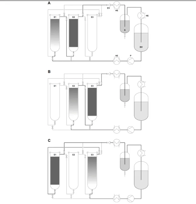
(11) FIGURES INDEX Pág. Figure 2-1: Schematic representation of a three-vessel SCFE plant for (A) extraction vessel 3 being reconditioned; (B) extraction vessel 1 being reconditioned; and, (C) extraction vessel 2 being reconditioned........................... 16 Figure 2-2: Comparison between the actual, pseudo-steady-state concentration of oil in the SC CO2 stream exiting an extraction vessel (dashed line), and the ........ 26 Figure 2-3: Comparison of the simulated curves for three iterations as a function of extraction time for (A) changes in the dimensionless concentration of ............ 28 Figure 2-4: Evolution of the dimensionless concentration of oil in the SC CO2 stream in an extraction vessel as function of time and axial position after reaching a pseudo-steady-state condition .............................................................. 30 Figure 2-5: Comparison of the performance of an extraction vessel between a two-vessel and three-vessel SCFE plant for the third iteration for (A) the time-dependency of the dimensionless concentration of ....................................... 33 Figure 3-1: Solvent cycle in a SCFE plant with three extraction vessels operating at 40 °C and 30 MPa as extraction conditions ....................................................... 37 Figure 3-2: Solvent cycle of the SCFE plant (Fig. 3-1) represented in a T-s diagram .................................................................................................................. 39 Figure 3-3: Effect of particle size on changes in operational cost for a two-vessel SCFE plant using QCO2 = 55 L/min (U = 2.8 mm/s) as a function of extraction time ....................................................................................................... 45 . x.
(12) Figure 3-4: Dimensionless oil concentration (C/Csat) at the exit of an extraction vessel placed in a two-vessel plant in function of extraction time for 0.5 ≤ dp ≤ 4 mm, using QCO2 = 55 L/min (U = 2.8 mm/s) .............................................. 46 Figure 3-5: Summary of the minimum operational cost in function of dp and U for a two-vessel SCFE plant .................................................................................. 48 Figure 3-6: Combined effect of dp and U on operational cost for industrial (A) three-vessel or (B) four-vessel SCFE plants as a function of extraction time ........................................................................................................................ 50 Figure 3-7: Summary of the minimum operational cost in function of dp and U for a SCFE plant with (A) n = 3, and (B) n = 4 extraction vessels ...................................... 51 Figure 3-8: Effect of extraction vessel number on operational cost in function of extraction time for a SCFE processing particles of 2 mm and using 110 L/min of CO2 ......................................................................................................... 52 Figure 3-9: Effect of number of extraction vessels in (A) the extraction yield curves for extraction of particles of 4 mm using 110 L/min of CO2 and (B) the dimensionless oil concentration of the CO2 stream exiting an extraction vessel...................................................................................................................... 53 Figure 4-1: Flow diagram of a supercritical fluid extraction plant differentiating the constituents of the solvents cycle, and the extraction vessels, interconnecting elements, and elements connecting them with the solvent cycle ....................................................................................................................... 62 Figure 4-2: Estimated cost index of a supercritical fluid plant that can operate at 30 MPa as a function of the number and volume of extraction vessel and FCO2 ........................................................................................................................ 68 . xi.
(13) Figure 4-3: Cumulative extraction curve, plant productivity curve, and unitary operational and production (operation plus capital) cost as a function of extraction time for the production of vegetable oil in a two-vessel supercritical fluid extraction plant operating with 6000 kg/h of CO2 at 40 °C and 30 MPa ....................................................................................................... 75 Figure 4-4: Oil production cost as a function of extraction time for selected supercritical fluid extraction plants carrying out extraction of a prepressed oilseed (containing 20% w/w oil) at 40 °C and 30 MPa........................................ 76 Figure 4-5: Oil production as a function of extraction time for selected (A) threevessel or (B) four-vessel supercritical fluid extraction plants carrying out extraction of a prepressed oilseed (containing 20% w/w oil) at 40 °C and 30 MPa ................................................................................................................... 81 Figure 5-1: Positive effect of extraction pressure on production cost in function of extraction time for two-vessel SCFE plants (Total extraction volume of 2 m3) operating at 40 ºC ......................................................................................... 93 Figure 5-2: Production cost comparison among two-vessel SCFE plants with the same annual productivity (550 ton of oil per year), operating at 40 ºC, resulting in different combinations of extraction pressure and total volume of plant. SCFE process presents economies of scale ............................................. 94 Figure 5-3: Positive effect of plant size on production cost in function of extraction time, for two-vessel SCFE plant operating at 40 ºC and 50 MPa ......... 95 Figure 5-4: Effect of extraction pressure on production cost in function of extraction time for SCFE plant with (A) three and (B) four 1-m3-vessels, operating at 40 ºC .................................................................................................. 97 . xii.
(14) Figure 5-5: Effect of number of extraction vessel on production costs in function of extraction time for a SCFE plant with extraction vessel of 1 m3 operating at 40 ºC and 50 MPa .............................................................................. 98 . xiii.
(15) PONTIFICIA UNIVERSIDAD CATOLICA DE CHILE ESCUELA DE INGENIERIA DESARROLLO DE UNA HERRAMEINTA DE SIMULACIÓN PARA LA OPTIMIZACIÓN ECONÓMICA DE UNA PLANTA DE EXTRACCIÓN PARA SUSTRATOS VEGETALES USANDO CO2 SUPERCRÍTICO Tesis enviada a la Dirección de Investigación y Postgrado en cumplimiento parcial de los requisitos para el grado de Doctor en Ciencias de la Ingeniería. GONZALO ALEXIS NÚÑEZ MONTOYA. RESUMEN La extracción con fluidos supercríticos de sustratos sólidos se ha aplicado comercialmente por mucho tiempo para aplicaciones como extracción de lúpulo, descafeinización de granos de café, extracción de sabores de hierbas y especias, extracción de oleaginosas, etc. A pesar de esto, en la literatura hay poca información sobre escalamiento y costeo de esta tecnología, lo cual generalmente es parte del know-how de fabricantes de plantas. El objetivo de esta tesis fue desarrollar una herramienta de simulación para estimar los costos en una planta de extracción con CO2 supercrítico y evaluar el efecto de parámetros relevantes en el proceso a nivel industrial. Esta tesis presenta estimaciones para costo de operación y de producción de la extracción de oleaginosas preprensadas con CO2 supercrítico, usando un nuevo algoritmo de simulación basado en un modelo predictivo. El costo de operación (rango estimado, 4,081-8,149 USD/kg de aceite) disminuye cuando el tamaño de partícula disminuye y la velocidad superficial del CO2 aumenta. Los costos de producción (rango estimado, 5,881 a 12,74 USD/kg de aceite) tiene al costo de capital como el ítem de mayor incertidumbre en las estimaciones. Bajo las mismas condiciones de extracción, si relación de aspecto (L/D) de los extractores disminuye, el costo de xiv.
(16) producción disminuye. En plantas de dos extractores, el costo de producción mínimo fue a 70 MPa. Sin embargo, en plantas de múltiples extractores, el costo de producción mínimo fue a 50 MPa. En todos los casos estudiados, el número de extractores y el volumen total de la planta tienen un efecto positivo sobre el costo de producción, lo que confirma se aplican economías de escala a este proceso. El tiempo óptimo de extracción, el grado de agotamiento del sustrato, y la productividad de la planta son factores a considerar al momento de tomar decisiones de inversión en esta tecnología.. Miembros de la Comisión de Tesis Doctoral José M. del Valle Lladser Claudio Gelmi Weston Héctor Jorquera González Julio Romero Figueroa Rudolf Eggers Cristian Vial Edwards Santiago, Abril, 2013. xv.
(17) PONTIFICIA UNIVERSIDAD CATOLICA DE CHILE ESCUELA DE INGENIERIA DEVELOPMENT OF A SIMULATION TOOL FOR THE ECONOMIC OPTIMIZATION OF AN EXTRACTION PLANT FOR VEGETABLE SUBSTRATES USING SUPERCRITICAL CO2 Thesis submitted to the Office of Research and Graduate Studies in partial fulfillment of the requirements for the Degree of Doctor in Engineering Sciences by GONZALO A. NÚÑEZ. ABSTRACT Supercritical fluid extraction of solid substrates has been applied comercially for a long time to several applications (including extraction of hops, decaffeination of coffe beans, extraction of flavors from herbs and spices, extraction of oilseed, among others). Despite of this, in literature there is little information about scaling-up and costing of this technology, which generally is part of the know-how of plant manufacturers. The objective of this thesis was to develop a simulation tool to estimate the costs in an industrial supercritical CO2 extraction plant and to evaluate the effect of relevants parameters in the extraction process. Particularly, this thesis presents estimates for operational and production costs of the supercritical CO2 extraction of prepressed oilseeds using a novel simulation algorithm based on the fully predictive shrinking core model for the inner mass transfer. Operational costs (estimated range of 4.081-8.149 USD/kg of oil) decrease when particle size decreases and superficial CO2 velocity increases. Production costs (estimated range of 5.881-12.74 USD/kg of oil) include the capital cost, which is one of the items with major uncertainties in the estimates. Under the same extraction conditions, a decreasing of the aspect ratio (L/D) of the extraction vessels has a positive effect on xvi.
(18) production cost. In two-vessel plant, the lowest production cost was reached at highest extraction pressure (70 MPa). However, in multi-vessel plants, the minimum production cost was at 50 MPa. In all cases studied, the number of extraction vessels and the total volume of the plant had a positive effect on production cost, confirming that economies of scale apply to this process. Finally, other factors (as optimal extraction time, exhaustion grade of the substrate, and productivity of the plant) should be take in count to make decisions about investment or to optimize the operation of an industrial plant.. Members of the Doctoral Thesis Committee: José M. del Valle Lladser Claudio Gelmi Weston Héctor Jorquera González Julio Romero Figueroa Rudolf Eggers Cristian Vial Edwards Santiago, April, 2013. xvii.
(19) 1. LIST OF PAPERS This thesis is based on scientific papers published in ISI journals. The papers are the following: − Núñez, G.A., Gelmi, C.A., and del Valle, J.M. (2011). Simulation of a supercritical carbon dioxide extraction plant with three extraction vessels. Computers & Chemical Engineering, 35(12), 2687-2695. − del Valle, J.M., Núñez, G.A., and Aravena, R.I. (2012). Supercritical CO2 oilseed extraction in multi-vessel plants. 1. Minimization of operational cost. Journal of Supercritical Fluids (submitted). − Núñez, G.A. and del Valle, J.M. (2012). Supercritical CO2 oilseed extraction in multi-vessel plants. 2. Effect of number and geometry of extractors on production cost. Journal of Supercritical Fluids (submitted). − Núñez, G.A. and del Valle, J.M. (2012). Supercritical CO2 oilseed extraction in multi-vessel plants. 3. Effect of extraction pressure and plant size on production cost. Journal of Supercritical Fluids (in progress)..
(20) 2. 1.. INTRODUCTION The SuperCritical Fluid Extraction (SCFE) of solid substrates has been carried. out on a commercial scale for more than two decades (Brunner, 2005). Large-scale implementation of the SCFE include coffee beans decaffeination (extraction vessels ≥ 20 m3) and the extraction of hops (extraction vessels ≈ 5 m3) (Brunner, 2005; del Valle and Aguilera, 1999) made mostly in Europe and the United States. Also, there are processes on a smaller scale such as extraction of essential oils, lipids, oleoresins, among others, which were reviewed and discussed by del Valle and Aguilera (1999) for its potential application in industries of food, pharmaceutical, and perfume in Latin America. Despite of the above, many companies still think that SCFE processes are too expensive because their high investment costs compared to the processes at low pressure, restricted only to high added-value products (Perrut, 2000). This is far from reality when large volumes of material are treated, such as cases of both coffee beans and hop cones processing, manufacture of paints, soil remediation, and waste treatment (Perrut, 2000; Rosa and Meireles, 2005). Also, in these processes there are economies of scale, where capital and operation cost per ton of product decreases with increasing the plant capacity (King et al., 1993). In addition, cost of equipments for industrial implementation of the SCFE has decreased in the last years, making this technology more attractive and competitive (Brunner, 2005; Rosa and Meireles, 2005). Even more, in the food industry the processing by SCFE could be the only way to meet the product specifications, which may have competitive advantages over other technologies (Brunner, 2005). In fact, a number of extraction units have been built in Asia for the extraction of phytochemicals and natural product’s nutraceuticals in the last decade (Rosa and Meireles, 2005) and in South America there are several investigations in the field of SCFE, although there are no industrial applications yet (del Valle et al., 2005). Therefore, it is curious that there is little information in literature about scaling and SCFE process optimization (del Valle et al., 2005). Most studies suggest mathematical expressions to estimate preliminary both capital (investment) and.
(21) 3. operating (production) costs based on information previously known for similar processes, or so-called estimates of Level 1 (errors ≤ 50%; Harrison et al., 2003) and almost non-existent cost estimates of Level 2 (where the estimation is based on the size of the principal process equipment; errors ≤ 30%) or higher. Indeed, I would like to bring to state of the art a reliable and systematic procedure for the design and economic optimization of SCFE processes. To achieve this purpose is essential to develop a simulation tool that can monitor the progress of the residual solute contents in a packed bed of solid substrate, as it passes through a SuperCritical CO2 (SC CO2) flow with dissolved solute, and that it be representative of an extraction vessel in an industrial process. This will allow to estimate the productivity of the extraction vessel depending on various equipment and process parameters. With this information I will be able to dimension all components of the plant and to estimate the investment and operating costs. The last step will be the economic optimization of the process. The results will help to evaluate the competitiveness of a SCFE process compared to traditional extraction processes for obtaining both commodities and high added-value products. 1.1. Supercritical fluid extraction of solid substrates with CO2 The SuperCritical Fluids (SCF) are substances that are above their critical. pressure and temperature, and whose main characteristic is that its density (related to power solvent, i.e., capacity of a substance to dissolve another) can change into a wide range (Brunner , 2005). Its transport properties are comparatively better than those of conventional organic solvents, that is, exhibit a high diffusivity and low viscosity (del Valle and Aguilera, 1999). Finally, the SCF, which are gases under normal conditions, can be easily removed from the extracts and solid matrices by mere expansion to pressure environment (Brunner, 2005), so that products treated with SCF are virtually free of waste solvent (del Valle and Aguilera, 1999)..
(22) 4. Among the SCFs, the carbon dioxide (CO2) is the most advantageous and used for food processing (Brunner, 2005) and other extraction processes. CO2 is not corrosive in the presence of water, is not flammable, non-toxic, and can be obtained from renewable resources in large quantities, with high purity, and low cost. In addition, it is recoverable at low cost and does not cause harm to the solutes (del Valle and Aguilera, 1999). Another advantage of using CO2 (Pc = 7.38 MPa, Tc = 31 ° C) is that it works at temperatures close to the environment, which prevents damage to heat-labile compounds. A typical solid extraction system with SC CO2 at laboratory or pilot plant scale (20-100 dm3) or larger, is composed of one or more extraction vessels, a series of flash tanks (for splitting the extract), a compressor or pump (solvent recirculation stage), a source of CO2, and auxiliary equipment such as heat exchangers (Brunner, 2005). The main advantage of a SCF Extaction (SCFE) process at pilot plant is its CO2 recovery capabalities, where the solvent is recycled to the system (Brunner, 2005). The SCFE process operation in a pilot plant consists of the following steps: (i) pretreated substrate is loaded into the extraction vessel. The substrate can be milled (average particle size 0.25 ≤ dp ≤ 2.0 mm, Reverchon and De Marco, 2006), prepressed (oilseeds), laminated, or pelletized, depending on the application; (ii) the extraction vessel is pressurized with CO2; (iii) once the desired extraction is reached pressure, the CO2 circulates through the entire bed to a predetermined rate flow; (iv) the rich-solute CO2 flows through an expansion valve, the solute precipitates and it is recovered in a separator; finally, (v) the CO2 is condensed , stored in a buffer tank, and recirculated to the cycle. At industrial scale, it is desirable to have an extraction process with multiple extraction vessels, which would emulate a countercurrent contact during the extraction, where CO2 is contacted with the substrate more exhausted first, and then with the more fresh substrate, in order to obtain a virtually continuous extract productio. The extract can be split according to the compound solubilities in CO2, for different separation pressures. Therefore, such plants are formed by at least two extraction vessels, where one or more are in service, and the last one is at a reconditioning stage (depressurization,.
(23) 5. unloading of the exhausted substrate, loading of the fresh substrate, and repressurization). This operation mode is convenient when the outlet solute concentration in the SCF of any of the extraction vessels does not reached the saturation, resulting in savings of solvent and energy. A good alternative to study the large-scale or industrial process is by simulation process. This allows to determine the effect of relevant paremeters on the extraction such as particle size (dp), superficial velocity (U) or mass flow rate (Q) of CO2, long-todiameter ratio (L/D) of extraction vessels, extraction pressure (P, between 30 to 70 MPa for oilseed extraction), among others, so it gives me the opportunity to systematically evaluate the costs the process. 1.2. Scaling-up of the supercritical CO2 extraction process To carry out a study to predict the behavior of a industrial-level SCFE process. one should understand the mechanisms involved influencing the extraction rate. This rate can be controlled by solubility or diffusion. When the extraction rate is controlled by solubility (e.g., in the early stages in the oil extraction) the rate of solvent-to-substrate ratio generally remains constant. When the extraction rate is controlled by diffusion (e.g., in the final stages of essential oils extraction from herbs and spices), the contact time between the solvent and the substrate increases, and the flow solvent-to-charged substrate ratio remains constant. However, the reliability of any scale procedure depends critically on the kinetic extraction data quality obtained in the laboratory or pilot plant, which depend on the experimental setup (del Valle et al., 2005). Lack et al. (2001) have listed the following parameters to design a SCFE process: raw material (pretreatment) and final product specifications; size and location of the plant; thermodynamic conditions for extraction and separation; mass transfer mechanisms, determined by diffusion (which depends on both particle size and distribution of compounds that are extracted in solid matrix) and process fluid-dynamics (influenced by both size and shape of particles, and the particle size distribution); consumption and energy optimization.
(24) 6. considerations (pumps and/or compressors); specific problems in the separation step; and selection and design of the components of the plant. Once the plant capacity is set, and extraction curves obtained in laboratory scale and/or pilot plant are analyzed, both optimal time for processing and solvent flow are determined, which allows setting the extraction vessel volume. An exhaustive extraction of the substrate is not always profitable. In general, the process is considered complete when it has recovered 90% of the extract, given the asymptotic form of the extraction curves. Longer processing times could increase operation costs of the plant but with negligible increases on production (del Valle et al., 2005). There are few studies on of scaling-up of SCFE processes in the literature. An key one was the work of Eggers and Sievers (1989) who studied a change of scale (1:10 in volume) for the extraction of Oenothera Bennis L. seeds (40 °C, 40 MPa bar). They used two criteria for scale-up, considering an external control on the mass transfer rate: solvent flow rate-to-loaded substrate ratio constant and residence time constant. del Valle et al. (2004) suggested caution applying simple procedures for scaling-up such as those syudied by Eggers and Sievers (1989) due to the complex relationship between the extraction rate and processing conditions, which does not depend only on a external mass transfer coefficient. Particularly, del Valle et al. (2004) showed that there are differences in the mass transfer phenomenon when is changed from a laboratory-scale to pilot plant. These differences could be explained by heterogenities of the flow, axial dispersion, or entrainment of solute droplets in the recycled CO2 (del Valle et al., 2004). Clavier et al. (1996) presented a procedure to extrapolate (scale-up) a SCFE process from pilot plant to industrial scale, whose objective was to determine operational conditions, an optimal configuration of the plant and its dimension, the number of extraction vessels, the capacity of the pump, among other. Those authors proposed that depending on the complexity or nature of the extraction process, what scaling-up criteria should be applied. For simple extractions, keeping U/Mo (being Mo the initial mass of substrate loaded within the extraction vessel) and MCO2/Mo (being MCO2 the mass of CO2 used in the extraction process) ratios constant is adequated. However, for complex.
(25) 7. extractions where both diffusion and solubility are important, or the extract is a complex mixture, the use of numerical software would help optimizing SCFE plant configuration and process itself. As example, Clavier et al. (1996) have applied their procedure to the oilseed extraction with SC CO2. Mezzomo et al. (2009) scaled-up the SCFE of peach almond oil with SC CO2 at 40 ºC , and 15 and 25 MPa, using four criteria: keeping constant solvent mass-to-substrate mass; CO2 flow rate-to-substrate mass; keeping constant both solvent mass-to-substrate mass and CO2 flow rate-to-substrate mass; and keeping constant solvent mass-to-substrate mass and Reynolds number; being the second and the third cases the better ones. They concluded that SCFE of peach almond was controlled by diffusion, and that the extraction curves coincided for small and large scales. Prado et al. (2011) have applied successfully the scaling-up (extraction vessel ratio equal to 1:15) of the extraction of both clove and sugarcane residue keeping MCO2/Mo constant. The shape of the extraction curves and yield in both raw materials were slightly higher in pilot plant than in laboratory scale, according with manufacturer information but opposite to literature information. Also, they applied a combined criterion to scale-up keeping both MCO2/Mo and QCO2/Mo constant, but changing QCO2/Mo they obtained the same results, concluding that their simple criterion was good enough. Prado et al. (2012) also applied MCO2/Mo constant as criterion to scale-up (1:15) the extraction of grape seeds with SC CO2 at 40 ºC and 35 MPa with good results, where extraction curves at different scales practically overlapped. Chapter 4 includes more detail about scaling-up of SCFE processes of the works mentioned in this section. 1.3. Costs in a supercritical CO2 extraction process Costs in a SCFE process include capital (investment) and operational cost.. Capital costs of a SCFE plant are related to the purchase of equipment for feed pretreatment, SCFE plant itself, utilities (cooling and heating systems, electric power, etc.) and other minor units. Generally, the SCFE plant represents 70-85% of total investment (del Valle et al., 2005). On the other hand, operation costs are dominated mainly by the overall consumption of energy in the process, given by the pressurization of extraction.
(26) 8. vessels, and heating and cooling of the CO2 current solvent. Also they include raw materials cost, labor, electricity, water (for processes and consumption), steam (if necessary), replacement of solvent (CO2), etc. (King et al., 1993; Lack and Seidlitz, 2001). An important aspect is the recovery of CO2 in the process, especially as the capacity of the plant is higher. The solvent recycling and their subsequent employment, in a proper recycling system, should allow reduce CO2 losses to less than 2% of all that is used in extraction (del Valle et al., 2005). There are some works in literature that studied the cost involved in a supercritical CO2 process at industrial scale. Passey (1994) studied the feasibility of a commercial SCFE plant to manufacture low-fat peanut, concluding that a plant capacity of 16000 L, which produces 1200 ton/year (2% of the market), with a capital cost of USD 6.1 million, had a net present value (NPV, 20 years) of USD 3-7 million (depending on the location of the plant) and a return-on-equity (ROE) of 42-59%. Novak and Robey (1989) studied the design and the economics in a SCFE process of flavor extracts from spices and herbs at 80 ºC and 30 MPa (as maximum extraction conditions), considering a base case and a high capacity case. In the base case, they proposed a multiproduct 2×973L SCFE plant, processing 770 ton/year of an spice, for a capital cost of USD 2.8 million, resulting in a production cost of 1.1 USD/kg of substrate. In the high capacity case the feed rate increased to 3060 ton/year of spice, resulting in an decreasing of the production cost to 0.5 USD/kg of substrate. Körner (1993) presented capital and operational cost for a SCFE plant for spices extraction with CO2 at 80 ºC and 40 MPa for three different capacities (450, 900, and 1800 ton/year of spice). The combination for capital and operational costs were the following: USD 3.1 millon and 4.868 USD/kg of spice; USD 3.9 million and 4.153 USD/kg of spice; and, USD 4.5 million and 3.679 USD/kg of spice, respectively (original values in Deutsche Marks, Oanda.com, 2011). Clavier et al. (1996) estimated costs for the oilseed extraction with SC CO2 at 40 ºC and 25 MPa. The capital cost for a 2×209L SCFE plant and mass flow rate of 2160 kg/h was estimated in USD 1.6 million, with a production cost equal to 5.089 USD/kg of seeds for 7 ton of extract per year or 4.479 USD/kg of seeds for 10.7 ton of extract per year (original.
(27) 9. values in French Francs, Oanda.com, 2011). For its part, Bravi et al. (2002) studied the optimization of a SCFE plant for extracting sunflower oil with SC CO2 to 28 MPa and 40 °C. They reported a production cost of 0.633 USD/kg of oil (value updated; Oanda.com, 2011) and concluded that the optimal number of extraction vessels were four, to treat 4380 kg/h of seeds, with a total CO2 flow of 60000 kg/h, extraction time of 10 minutes, and separation pressure of 16.7 MPa. Prado et al. (2010) reported a cost of 17.2 USD/kg of oil for the extraction of palm tree using SC CO2 at 40-55 ºC and 20-30 MPa. Fiori (2010) reported 7.82 USD/kg of oil (value updated, Oanda.com, 2011) for the extraction of grape seed with SC CO2 at 60 ºC and 55 MPa compared with for the grape seed extraction with SC CO2 (Prado et al., 2012). Mezzomo et al. (2011) reported a production cost of 4.64 USD/kg of oil for peach kernel extraction with SC CO2 at 40 ºC and 20 MPa. Prado et al. (2012) estimated the production cost for the SCFE of grape seeds at 40 ºC and 35 MPa, determining a value 11.9 USD/kg (updated value, Oanda.com, 2011). Comparing the works of Fiori (2010) and Prado et al. (2012), it might be concluded that pressure has a positive effect on the production cost. Chapter 4 includes more detail about economics in SCFE processes. 1.4. Hypothesis The simulation of an extraction plant of vegetable substrates using supercritical. CO2 as a solvent allows: “Optimize both operational (number of extraction vessels, extraction and separation pressure, among others) and economic (capital and operation costs) parameters of the process”, and “The above will allow to evaluate systematically the costs involved in a supercritical CO2 extraction process of oilseeds”. Indeed, it could evalquate the economic competitiveness of an extraction process with supercritical CO2 as the solvent comparing with traditional extraction processes for.
(28) 10. obtaining commodities (e.g. edible oils) and/or high added-value products (e.g. carotenoids). 1.5. Objectives The main objective of this thesis is to develop a simulation tool to study the costs. involved in an industrial extraction plant of vegetable substrates using supercritical CO2 (SC CO2) as the solvent in function of extraction time and relevants parameters for the process. The specific objectives of this thesis are the following: 1. To simulate a supercritical CO2 extraction process of oilseeds at industrial scale. 2. To study the effect on the extraction process of the following relevant parameters: particle size (dp); superficial velocity (U) or mass flow rate (Q) of the CO2; number of extraction vessels (n); length-to-diameter ratio (L/D) of the extraction vessels; and extraction pressure (Pext). Indeed, to determine the optimal ones using the simulation tool of (1). 3. To determine both operational and capital costs of a SCFE process to evaluate the effect of the parameters listed in (2), and compare those costs with estimates proposed in the literature..
(29) 11. 2.. SIMULATION. OF. A. SUPERCRITICAL. CARBON. DIOXIDE. EXTRACTION PLANT WITH THREE EXTRACTION VESSELS Abstract Although SuperCritical Fluid Extraction (SCFE) has been successfully applied commercially the last three decades, there is no systematic procedure or computational tool in literature to scale-up and optimize it. This work proposes an algorithm to simulate dynamics in a multi-vessel (≥ three) high-pressure SCFE plant where extraction vessels operate in batches, and is thus forced to use simulated-countercurrent flow configuration to improve efficiency. The algorithm is applied to a three-vessel SCFE plant using a shrinking-core model to describe inner mass transfer in the substrate. As example, the extraction of oil from prepressed seeds using supercritical CO2 at 40 ºC and 30 MPa is simulated. After three cycles the process reaches a pseudo-steady-state condition that simplifies the estimation of plant productivity. Use of a three- instead of two-vessel SCFE plant increases oil concentration in the stream exiting the plant and decreases CO2 usage at the expense of increasing extraction time. Keywords: coupled partial differential equations; industrial scale; mathematical modeling; packed bed; simulation; supercritical fluid extraction.. 2.1. Introduction There are many successful examples of commercial application of SuperCritical. Fluid Extraction (SCFE) over the last three decades, including the decaffeination of green or roasted coffee beans, the production of hop extracts, the extraction of herb and spice flavors, and the extraction of oilseed lipids (Brunner, 2005). These applications use CO2 as the solvent, mainly because CO2 is non-flammable, non-corrosive in the presence of water, and non-toxic; can be obtained from renewable resources in large quantities, with high purity, and at low cost; and is easily recoverable without harming the substrate nor the extract (Brunner, 2005). Recommended SCFE conditions include a.
(30) 12. near-critical temperature (Tc = 304 K for CO2) and a pressure 5-to-10 times above the critical (Pc = 7.4 MPa for CO2) (Brunner, 2005) so that SC CO2 extraction has the additional advantage of being carried out at a near-environmental temperature, thus preventing thermal damage to labile compounds. However, SC CO2 extraction has the disadvantage of being a high-pressure process, thus limiting operation with solid substrates (the case of all commercial examples above) to a batchwise mode (Brunner, 2005). Industrial SCFE plants have two or more extraction vessels (i) to avoid dead times in the process, and (ii) to reduce solvent usage and energy requirements for solvent recycling. Indeed, in these SCFE plants while two or more extraction vessels are simultaneously in service, the remaining one is being reconditioned (a stage considering four steps: de-pressurization, unloading of exhausted substrate, loading of fresh substrate, and re-pressurization). This type of operation enables a virtually continuous extraction, even though SCFE of solid substrates is an inherently batch process, and is most desirable when solute concentration in the SC CO2 stream exiting the first extraction vessel does not get saturated with solute and advantage in taken of (an) additional extraction vessel(s) to save solvent and energy in multi-vessel plants having three or more. When an industrial SCFE plant has two vessels, cumulative extraction curves (solute yield versus extraction time) virtually coincide with those in pilot plant units having solvent recycling capabilities and a single extraction vessel, because extraction vessels work one at a time with recycled SC CO2. This is not the case in a multi-vessel (three, Fig. 1, or more vessels) SCFE plant, where the contact between the solid substrate and SC CO2 during extraction emulates countercurrent contact. In a multi-vessel SCFE plant, SC CO2 is contacted first with the more exhausted substrate and then successively with progressively fresher substrate. Proposed mass transfer models for SCFE typically simulate SCFE plants with only one or two extraction vessels, and to the best of our knowledge, there are no computational tools to simulate extraction dynamics in SCFE plants having three or more extraction vessels where two or more operate simultaneously. Many of these mass.
(31) 13. transfer models apply shrinking-core (Goto et al., 1996), or broken-and-intact-cells (Sovova, 2005) hypothesis to a single extraction vessel. Applications of the shrinkingcore model include the SCFE extraction of oleoresins from ginger (Roy et al., 1996) and nutmeg (Machmudah et al., 2006), and of lipids from grape seeds (Germain et al., 2005) and sunflower seeds (Salgin et al., 2006). On the other hand, applications of the brokenand-intact-cells model include the SCFE extraction of lipids from fennel and other seeds (Reverchon et al., 1999; Reverchon and Marrone, 2001) and apricot kernels (Özkal et al., 2005), and of oleoresins from nutmeg (Machmudah et al., 2006). Despite the numerous commercial applications of SCFE, there is limited literature on SCFE process scale-up and design. Reports include simple criteria for scale-up (Eggers and Sievers, 1989) and guides for cost evaluation (Passey, 1994; Perrut, 2000; Rosa and Meireles, 2005) but in our opinion these procedures are not systematic or reliable enough for scaling-up and designing purposes. We believe there is a need for more complex and predictive tools to simulate SCFE plants for solid substrates, which are paramount to economically optimize industrial SCFE processes. The objective of this work was to model and numerically simulate mass transfer phenomena in an industrial SCFE plant having multiple extraction vessels. For that we developed an algorithm to simulate the evolution in dissolved solute concentration in the SC CO2 exiting the last of several packed bed extraction vessels in an industrial SCFE plant, where the mass transfer from the solid substrate to the SC CO2 stream occurs according to a shrinking-core mechanism. We applied and tested our model to the extraction of oil from prepressed seeds in a three-vessel SCFE plant using SC CO2 at 40 ºC and 30 MPa as the solvent. Extraction conditions do not need to be modified, and the SCFE plant does not require more than three extraction vessels of the selected example as a proof-of-concept (oil extraction in preceding vessels in the solvent cycle affects initial stages of an SCFE process for a solid substrate by imposing variable inlet conditions). It is not the purpose of this manuscript to use our computational tool to economically optimize the design of SCFE processes for the extraction of solid substrates. It is however an important step in our long-term objective which is to.
(32) 14. contribute to the state of the art with a systematic and reliable designing procedure for industrial SCFE plants. 2.2. Model development for a multi-vessel SCFE plant This section explains the mass transfer problem in an industrial SCFE plant. having multiple extraction vessels and describes the model developed to mathematically describe it. The mass transfer problem in an two-vessel SCFE plant is already solved, but there is a need for an algorithm to simulate a SCFE plant having three or more extraction vessels that interact through the SC CO2 stream connecting them (i.e., when the entering SC CO2 stream has a time-dependent solute concentration). This section includes a description of the operation in a three-vessel SCFE plan, the mathematical model, the algorithm of numerical solution and its implementation, and the conditions for an illustrative example. 2.2.1 The problem of SCFE plants with three extraction vessels Fig. 2-1 compares the three configurations of the solvent cycle in a three-vessel SCFE plant. In Fig. 2-1A extraction vessel 1 contains partially extracted substrate, vessel 2 contains fresher substrate, and vessel 3 is being reconditioned; in Fig. 2-1B vessel 1 with exhausted substrate is taken out the solvent cycle, vessel 2 with partially extracted substrate is moved forward in the solvent cycle, and vessel 3 with fresh substrate is taken in at the end into the solvent cycle; and, finally, in Fig. 2-1C exhausted vessel 2 is taken out of, partially exhausted vessel 3 is moved forward along, and fresh vessel 1 is moved into the solvent cycle. In all cases, the SC CO2 moves from a vessel with more nearly exhausted substrate, to a vessel with fresher substrate. In general in an n-vessel SCFE plant, (n – 1) extraction vessels are connected using a simulated countercurrent contact whereas reconditioning steps are carried out in the last extraction vessel. Available mass transfer models for one vessel laboratory or pilot plant SCFE units do not take into account the interaction between two consecutive extraction vessels in industrial SCFE plants having three or more, where the exiting stream of one vessel.
(33) 15. corresponds to the entering stream of the next one in the solvent cycle. This problem has no trivial numerical solution and requires special treatment of the border conditions to simulate the mass transfer in an industrial SCFE plant. In a two-vessel SCFE plant the process is similar to the that in a one-vessel SCFE plant, because the second extraction vessel enters the solvent cycle only when the first one leaves the solvent cycle so that the solid substrate at the entrance of the extraction vessel is also always in contact with solute-lean SC CO2. Solute concentration in the SC CO2 stream entering an extraction vessel in an industrial SCFE plant having three or more extraction vessels changes with time because CO2 proceeds from one vessel to the next, and removes solute from substrate that contains progressively more solute (simulated countercurrent contact). Furthermore, inlet solute concentration in the SC CO2 also experiences step changes (decreases) when the sequence of extraction vessels in the solvent cycle is altered to take out the one with exhausted substrate and take in the one with fresh substrate. This work presents the simulation of the mass transfer dynamics of a single extraction vessel in a three-vessel SCFE plant during a complete extraction cycle, up to reaching a pseudo steady-state condition identified by comparing the mass transfer behavior in successive cycles. The cycle is defined as the time required for completing extraction of substrate in one extraction vessel, which includes extraction itself and the reconditioning steps. This is as problem that has not been addressed in literature on extraction, possibly because in conventional solid liquid extraction (at standard pressure) it is possible to feed fresh substrate to the extraction apparatus, and remove the exhausted substrate from it without difficulties, unlike in extractions of solids at high pressure (SCFEs). Thus, extractions can be carried out at standard pressure in a true countercurrent mode (true steady state conditions can be established). To our knowledge few applications in chemical engineering bear resemblance to ours, e.g., adsorptive separations using simulated moving beds (Dünnebier et al., 2000) (some using a SC mixture as the mobile phase, Brunner and Johannsen, 2006). However, simulated.
(34) 16. Figure 2-1: Schematic representation of a three-vessel SCFE plant for (A) extraction vessel 3 being reconditioned; (B) extraction vessel 1 being reconditioned; and, (C) extraction vessel 2 being reconditioned. Thicker lines indicate the corresponding solvent cycles. The components of the three- vessel SCFE plant are the following: (Ei) extraction vessels (with i = 1, 2, 3); (S) separator; (BV) buffer vessel for CO2; (EV) expansion valve; (HE) heat exchanger; and, (P) pump..
(35) 17. moving beds are so different from our application that a mathematical solution of the problem is required, as attempted in our work. 2.2.2 Mass transfer model We used the quasi-stationary state version of the shrinking-core model of Goto et al. (1996) to simulate the SCFE process because of its predictive capabilities for lipid extraction from prepressed oilseeds using SC CO2 as the solvent (Germain et al., 2005; del Valle et al., 2006). In particular, the shrinking-core model describes the physical situation of a boundary between a solute-rich center (core) and an outside region where a dissolved solute gradient develops, and located in a receding radial position (r = rc) in a porous particle (i.e., the core shrinks as extraction proceeds). The model assumes isothermal conditions, a spherically-shaped porous matrix with evenly distributed solute initially, irreversible desorption of the solute, and constant physical properties of the SC CO2 stream during extraction. These conditions are appropriated for the SC CO2 extraction of prepressed oilseeds (del Valle et al., 2006). Although prepressed and pelletized substrates are cylindrically shaped, Ma and Evans (1968) showed that dimensionless solutions for the extraction of various bodies of regular geometry in a perfectly agitated medium virtually superimposed when using as the characteristic dimension of the particle three times the ratio between its total volume and external surface (R, in the case of a sphere). In the typical case of a cylinder with an aspect (height-to-diameter) ratio of one, this characteristic dimension coincides with the cylinder radius. del Valle et al. (2006) adopted this assumption and showed that shear efforts during pre-pressing obliterated cells walls in parenchymatous tissue of oilseeds thus releasing oils to the interconnected pore network that resulted from applying this pretreatment. The equations of the shrinking-core model represent the differential mass balance for the solute in a packed bed describing the external mass transfer in the SC CO2 phase, Eq. (2.1), inner mass transfer by diffusion in porous substrate particles, Eq. (2.2),.
(36) 18. shrinking of the solute-rich core within solid particles, Eq. (2.3), and calculation of extraction yield, Eq. (2.4).. ∂C ∂C ∂ 2 C (1− ε ) 3kf +u = DL 2 + C −C ∂t ∂z ε R p r= R ∂z. (. ). De ∂ ⎛ 2 ∂Cp ⎞ r =0 r 2 ∂r ⎜⎝ ∂r ⎟⎠. (. ∂rc R2 kf = C − Cp r= R ∂t rc2Co. (2.1). (2.2). ). (2.3). ∂E FCO2 = ⋅C z= L ∂t M. (2.4). Initial conditions (t = 0) to solve these partial differential equations are that solute concentration in the SC CO2 phase is zero along the entire extraction vessel, Eq. (2.5), that the radius of the core equals the particle radius for all particles in the vessel, Eq. (2.6), and that extraction yield is zero at the beginning of the extraction.. C t=0 = 0. 0≤z≤ H. (2.5). rc t=0 = R. 0≤z≤ H. (2.6). E t=0 = 0. (2.7). Boundary conditions, on the other hand, include the Danckwerts boundary conditions for axial dispersion at the inlet (z = 0), Eq. (2.8), and outlet (z = H), Eq. (2.9), of the extraction vessel; the continuity equation for mass transfer from the porous space in the solid particle (diffusion) to the SC CO2 phase (convection), at the substratesolvent boundary (r = R), Eq. (2.10); and the equilibrium condition between the inner.
(37) 19. condensed solute core and the outer pore space (SC CO2 saturated with solute) at the shrinking-core boundary (r = rc), Eq. (2.11).. ∂C ∂z. DL. ∂C ∂z. De. = uC. t≥0. (2.8). t≥0. (2.9). t≥0. (2.10). t≥0. (2.11). z=0. =0 z= H. ∂Cp ∂r. (. = kf C − Cp r= R. r= R. ). Cp = Csat r=r c. To solve this problem numerically, we transformed the variables into dimensionless forms using the following definitions: Y = C Csat ;. θ = t ⋅u L;. ζ = z L;. δ =r R;. δ c = rc R ;. u =U ε;. (. ap = 3 R ;. X = Cp Csat ;. b = Csat Co ;. ). Bi = kf ⋅ R De ; Pe = u ⋅ L DL ; and τ e = u kf ⋅ ap ⋅ L . The model equations and initial. and boundary conditions become Eqs. (2.12)-(2.22) when written in dimensionless form:. ∂Y ∂Y 1 ∂ 2 Y (1− ε ) 1 + = + X δ=1 − Y ∂θ ∂ζ Pe ∂ζ 2 ε τe. (. De ∂ ⎛ 2 ∂ X ⎞ δ =0 δ 2 ∂δ ⎜⎝ ∂δ ⎟⎠ ∂δ c b 1 = Y − X δ=1 ∂θ 3δ c2 τe. (. ∂S b⋅ ε = Y ∂θ (1− ε ) ζ=1. ). (2.12). (2.13). ). (2.14). (2.15).
(38) 20. Y θ=0 = 0. 0 ≤ ζ ≤1. (2.16). δ c θ=0 = 1. 0 ≤ ζ ≤1. (2.17). S θ=0 = 0. 0 ≤ ζ ≤1. ∂Y ∂ζ. =0. θ≥0. (2.19). = PeY. θ≥0. (2.20). θ≥0. (2.21). θ≥0. (2.22). ∂Y ∂ζ. ∂X ∂δ X. (2.18). ζ=1. ζ=0. δ=1. δ=δ c. (. = Bi Y − X δ=1. =1. ). 2.2.3 Numerical solution of the problem using MATLAB The spatial derivatives of the model were computed using second-order central finite differences (as previously used by Germain et al., 2005). We divided both the extraction vessel and the particles in 30 nodes, resulting in a system with sixty-one differential equations: (i) thirty differential equations to account for mass transfer from the particles to SC CO2 by convection and solute conservation in the extraction vessel; (ii) thirty differential equations to account for mass transfer in the particles by diffusion; and, (iii) one differential equation to calculate cumulative extraction curves. We solved the resulting time-dependent equations using the ode15s solver (variable order solver based on the numerical differentiation formulas) of MATLAB R2008b in a personal computer with processor Intel Core 2 Duo @ 1.83 GHz and 1 GB of RAM..
(39) 21. Eq. (2.23) defines the vector with the conditions at the beginning of every stage in the extraction:. IC i = ⎡ I Ai I Bi ⎣. I Ci ⎤ , ⎦. (2.23). where IAi represents dimensionless solute concentration in the SC CO2 phase, IBi, the dimensionless radius of the solute-rich particle core; and ICi, the extraction yield (scalar), all at the end of extraction stage (i – 1). At the beginning of the process, when the first extraction vessel in the solvent cycle has fresh substrate, the elements in Eq. (2.23) take the following values: IAi = 0, which is a vector composed of 30 zeros, and represents the SC CO2 phase without solute; IBi = I, is a vector composed of 30 ones and represents the initial dimensionless radius of the solute-rich core of the particles, when particles are unextracted; and ICi = 0, is an scalar and represents null yield. For the next stages, the elements in Eq. (2.23) are updated constantly according with the evolution of the oil concentration through the extraction vessels. The updating process in this work is extended up to reaching a pseudo-steady-state (when the assumed evolution in solute concentration in the stream entering the extraction vessel virtually coincides with actual, updated, one). In turn, the inlet SC CO2 stream of the extraction vessel varies depending on how much solute it is removed in the preceding extraction vessel. Thus, when the inlet stream of the extraction vessel comes from the buffer vessel with recycled CO2 (solute-lean), solute concentration is constant and corresponds to solute solubility in CO2 at separation conditions, Eq. (2.24):. Y θ=0 = Csep Csat. (2.24). On the other hand, when the inlet SC CO2 stream of an extraction vessel is the SC CO2 stream exiting another vessel, the solute concentration varies according to a history stored as indicated in Eq. (2.25):.
(40) 22. Yi θ=0 = y i-1 ζ=1 ( t ) ,. (2.25). where vector y i-1 ζ=1 ( t ) stores the history of the SC CO2 stream exiting (ζ = 1) the extraction vessel in extraction stage (i – 1), and vector Yi θ=0 indicates the initial solute concentration at the beginning of extraction stage i for any extraction vessel. All inlet streams represented by Eq. (2.24) or Eq. (2.25) are fed to the next extraction stage through a “zero node”, which is physically located at the entrance of the extraction vessel. This is required, because of the use of central-type finite differences in which any changes in node condition are defined using the information from the preceding and following nodes. Depending on the case, in order to initialize our algorithm, we assigned the elements of Yi θ=0 (Eq. (2.24)) or Y θ=0 (Eq. (2.25)) to the zero node at the entrance of the extraction vessel. 2.2.4 Implementation of the algorithm Firstly, we determined the state of the substrate at the beginning of the extraction, which could be fresh or partially extracted. For fresh substrate (e.g., first stage i = 1), the initial state in the extraction vessel is given by Eq. (2.23), with IAi = 0, IBi = I, and ICi = 0, and extraction is simulated as being carried out by a solute-rich SC CO2 stream having a solute concentration given by Eq. (2.25). Secondly, to simulate the whole extraction process, we updated the values in vector Yi θ=0 , Eq. (2.25), and matrix ICi, Eq. (2.23), every 60 seconds. For partially extracted substrate after the switch time (cf. Fig. 2), we applied Eq. (2.23) updated at this point of the extraction, and simulated extraction as being carried out by recycled SC CO2 using Eq. (2.24). Finally, we stored the outputs of the algorithm in matrix Hi (t), Eq. (2.26): Hi (t ) = ⎡ t i ⎣⎢. y i ζ=1 ( t ) S i ( t ) ⎤ ⎦⎥ ,. (2.26).
(41) 23. where Hi (t ) is a matrix that contains the outputs of the simulation for an extraction unit at any stage i. Hi (t ) has three column vectors, where we recorded the extraction time ( t i , in seconds), the concentration of the SC CO2 stream exiting the extraction vessel. (). ( y i ζ=1 ( t ) , dimensionless), and the extraction yield ( S i t , dimensionless) as a function of time. We used vector y i ζ=1 ( t ) as an input for the next extraction vessel. 2.2.5 Operational conditions of the oil extraction from prepressed rapeseeds For a three-vessel SCFE plant, the total extraction volume of the plant was 6 m3, and each vessel (VE = 2 m3) had an inner diameter of 0.8 m and a height of 4 m. The extraction conditions in the plant were 40 ºC and 30 MPa, whereas the separation conditions were arbitrarily set at 60 ºC and 8 MPa. The physical properties (ρ and µ) of CO2 were estimated using NIST Database (Lemmon et al., 2010) for pure CO2. Extraction was extended to remove 90% of the oil in the substrate, using a SC CO2 mass flow rate of 0.915 kg/s (3300 kg/h). Particle size (dp), and porosity (εb) and bulk density (ρb) of the bed were assumed (typical values for packed beds of vegetable substrates). Finally, the assumed initial oil content (Co) in prepressed oilseeds was 20% (w/w). The model parameters were calculated or estimated using correlations or mathematical expressions available in the literature. Table 2-1 summarizes the values of model parameters. We estimated oil solubility in SC CO2 (Csat and Csep) using the correlation of del Valle, et al. (2012a). In addition, we estimated the effective diffusivity (De = D12·F) as the product of value of the microstructural correction factor (F) the reported by del Valle et al. (2006) and the diffusivity of oil in CO2 (D12) estimated using the correlation of Funazukuri et al. (2009). Finally, we estimated the external mass transfer coefficient (kf) using the correlation of King and Catchpole (1993), and the axial dispersion coefficient (DL) using the correlation of Catchpole et al. (1996)..
(42) 24. Table 2-1: Model parameters calculated at extraction conditions (Pext = 30 MPa; Text = 40 ºC), and separation conditions (Psep = 8 MPa; Tsep = 60 ºC) Parameter. As function of. Value. Unit 3. V. -. 6. (assumed). m. VE. -. 2. (assumed). m3. L/Dext. -. 5. (assumed). -. Dext. f (VE, L/Dext). 0.8. (calculated). m. L. f (VE, Dext). 4. (calculated). m. FCO2. -. 0.915. (assumed). kg·s-1. dp. -. 0.005. (assumed). m. εb. -. 0.6. (assumed). -. ρb. -. 500. (assumed). kg·m-3. 0.2. (assumed). kg oil·kg-1 substrate. Co. -. ρ. f (Pext, Text). 909.9. (calculated). kg·m-3. ρsep. f (Psep, Tsep). 191.6. (calculated). kg·m-3. µ. f (Pext, Text). 9.4 × 10⁻⁵. (calculated). Pa·s. U. f (ρ, FCO2, Dext). 0.002. (calculated). m·s-1. u. f (U, ε). 0.003. (calculated). m·s-1. Csat. f (Text, ρ). 7.9 × 10⁻³. (calculated). kg oil·kg-1 CO2. Csep. f (Tsep, ρsep). 1.6 × 10⁻⁴. (calculated). kg oil·kg-1 CO2. D12. f (Text, ρ). 3.0 × 10⁻⁹. (calculated). m2·s-1. F. -. 0.172. (assumed). -. -10. De. f (F, D12). 5.2×10. (calculated). m2·s-1. Re. f (dp, ρ, µ, U). 97. (calculated). -. DL. f (Re, L, u). 1.9×10⁻⁴. (calculated). m2·s-1. Sc. f (ρ, µ, D12). 34. (calculated). -. kf. f (Re, Sc). 3.3×10⁻⁵. (calculated). m·s-1.
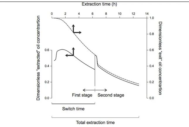
(43) 25. 2.3. Results and Discussion This section first explains the difference between the oil extracted in a vessel,. expressed as the product of the mass flow rate of SC CO2 and the difference in concentration of oil between the streams entering and exiting the vessel, and the oil extracted in the two vessels in the solvent cycle, expressed as the product of the mass flow rate of SC CO2 and the concentration of oil in the stream exiting the second vessel in the solvent cycle. This explanation is necessary to clearly understand the advantage of having three or more vessels in an industrial SCFE plant. A discussion follows about the number of iterations required to reach the pseudo-steady-state condition characterizing the operation of a typical extraction vessel in a multi-vessel plant. Finally the pseudosteady-state conditions and productivities of a two- and three-vessel SCFE plants are compared. Fig. 2-2 compares the time dependency between the actual, pseudo-steady-state concentration of oil in the SC CO2 stream exiting an extraction vessel, and the difference in concentration between that stream and the SC CO2 stream entering the extraction vessel. This comparison is important because the difference between inlet and outlet concentration, which we will refer to as the concentration of “extracted” oil, accounts solely for the oil extracted in the vessel. Fig. 2-2 defines a switch time when the extraction vessel remains in the same position (first or second) in the solvent cycle, and the extraction time (twice the switch time) when the extraction vessel remains in the solvent cycle. For the purpose of discussion, the cycle time (tc) includes the reconditioning of the extraction vessel and corresponds to the addition of the switch time and the extraction time (three times the switch time). The number of batches in one year that each extraction vessel in a multi-vessel SCFE plant can be estimated roughly as the total production time divided by the cycle time. Thus, a three-vessel SCFE plant operating continuously (three 8 h-shifts per day) 300 days per year, allows a grand total of ca. 3×300×24 / tc batches per year..
(44) 26. Figure 2-2: Comparison between the actual, pseudo-steady-state concentration of oil in the SC CO2 stream exiting an extraction vessel (dashed line), and the “extracted” oil stream (solid line, defined as the difference in concentration between the stream represented by dashed line and the SC CO2 stream entering the extraction vessel). The line in the middle of the graph defines the switch time (t = 6.35 h) as that time when the extraction vessel remains in the same position in the solvent cycle. Total extraction time (twice the switch time) defines the whole period when the extraction vessel remains in the solvent cycle. This is important in defining the productivity of the SCFE plant. In Fig. 2-2, concentrations are expressed in dimensionless form (Y = C/Csat), so that Y = 1 represents a SC CO2 stream saturated with oil (Csat = 7.915 g oil/kg CO2), and Y = 0, a stream without oil. The outlet concentration and the “extracted” oil concentration were computed and updated every 60 seconds in the simulation. The two curves in Fig. 2-2 do not begin at t = 0 but at t = 1200 s, because this corresponds to the residence time of SC.
(45) 27. CO2 in the extraction vessel. The same consideration applies to Fig. 2-3 and Fig. 2-4. The concentration of “extracted” oil in the SC CO2 stream exiting the second extraction vessel in the solvent cycle cannot begin in Y = 1 because part of the oil in the stream is removed from the substrate in the first extraction vessel. The discontinuity in the curve of “extracted” oil for the second stage (at 6.35 h) corresponds to a switch in the feed of the extraction vessel from an oil-containing stream from a preceding vessel (when the vessel is located second in the solvent cycle) to the oil-lean recycled SC CO2 stream (when the vessel is located first in the solvent cycle). This switch results in an abrupt increase in extraction rate due the sudden increase in the driving force for mass transfer. This abrupt increase in extraction rate is in turn responsible for the shoulder observed in Fig. 2-2 for the first stage in the extraction process; the initially high concentration of oil in the entering stream is responsible for a low initial driving force for mass transfer in the second vessel in the solvent cycle. Fig. 2-3 shows (A) changes in the dimensionless concentration of “extracted” oil in the SC CO2 stream exiting an extraction vessel and (B) the cumulative oil extraction curve in the same vessel in a three-vessel SCFE plant for a first, second, and third iterations as a function of extraction time. Extraction times were 12.5 h (cycle time 18.8 h) for the first iteration, 12.9 h (cycle time 19.4 h) for the second, and 12.8 h (cycle time 19.2 h) for the third (Fig. 2-3A). Percent changes (absolute basis) decreased from 3% between the first and second iteration, to 1% between the second and the third ones. Corresponding simulated cumulative oil extraction curves nearly overlapped suggesting that three iterations are enough to converge to a pseudo-steady-state operational condition of the SCFE plant (Fig. 2-3B). In fact, discrepancies in cumulative oil extraction between the second and third simulations were in average smaller than 0.1%. This observation simplifies the analysis of the SCFE plant because the performance of any extraction vessel in the plant is roughly equivalent to that of the extraction vessel in Fig. 2-3 after the third iteration..
(46) 28. Figure 2-3: Comparison of the simulated curves for three iterations as a function of extraction time for (A) changes in the dimensionless concentration of “extracted” oil in the SC CO2 stream exiting an extraction vessel and (B) the cumulative oil extraction curve for the same vessel in a three-vessel SCFE plant. The switch time was 5.53, 6.60, and 6.35 h, for first, second, and third iterations..
Figure


+7


Documento similar
In the preparation of this report, the Venice Commission has relied on the comments of its rapporteurs; its recently adopted Report on Respect for Democracy, Human Rights and the Rule
Therefore, these aspects would confirm that improvements possibly would arise from gains in impulse at swim start obtained specifically on lower limbs with the experimental
The assessment of the value of the filtration process was assayed for the nanoformulation and, although the results showed no significant changes in the particle size when using
The main goal of this thesis is to contribute to the knowledge in planetary science through the study of the upper atmosphere of giant planets undergoing hydrody- namic escape. We
(2007) Accumulation of arsenic in tissues of rice plant (Oryza sativa L.) and its 974. distribution in fractions of
In the present work, the supercritical fluid extraction of heather, marigold and the combined extraction of both plants (50:50 heather + marigold) was carried out, the concentration
“ CLIL describes a pedagogic approach in which language and subject area content are learnt in combination, where the language is used as a tool to develop new learning from a
"Fouling Out the American Pastoral: Rereading Philip Roth's The Great American Novel." Upon Further Review: Sports in American Literature.. Michael Cocchiarale and
