Quality driven software product lines
92
0
0
Texto completo
(2) TABLE OF CONTENTS Abstract ........................................................................................................................................... 5 1. Introduction ............................................................................................................................. 6 2. Background .............................................................................................................................. 7 2.1 Quality Attributes .................................................................................................................. 7 2.2 Software Architecture ........................................................................................................... 8 2.2.1 Tactics .................................................................................................................................. 9 2.2.2 Reference Architectures................................................................................................... 10 2.3 Enterprise Software Applications ...................................................................................... 11 2.4 Model Driven Engineering ................................................................................................. 11 2.5 Software Product Line Engineering .................................................................................. 13 2.6 Related Work....................................................................................................................... 14 3. Case Study .............................................................................................................................. 17 4. Proposal .................................................................................................................................. 21 General Process for Product Derivation .................................................................................... 21 4.1. Define the Software Product Line Scope .......................................................................... 22 4.1.1. Functional Scope Definition ............................................................................................ 22 4.1.2. Quality Scope Definition ................................................................................................. 24 4.2. Determine Design Decisions of Product Line Members ................................................. 29 4.2.1. Identify Enterprise Design Patterns to Promote Variants from the QAs Model....... 29 4.2.2. Reference Architecture Definition ................................................................................. 31 4.3. Perform Code Generation ................................................................................................. 54 4.3.1. Constructing the Product Line Member Concrete Architecture ................................ 55 4.3.2. General Delegation Strategy ........................................................................................... 58 4.3.3. Concrete Generation Strategy ........................................................................................ 64 5. Technologies Involved in Product Line Members Derivation ........................................... 76 5.1 Create a Model Based on the DMM ................................................................................... 77 5.2 Select a Configuration From the QAs Variability Model ................................................ 79 5.3 Execute Generation Workflow ........................................................................................... 81 6. Conclusions ........................................................................................................................... 81 7. Bibliography .......................................................................................................................... 82 Annex 1. Query Declaration example ............................................................................................ 89 Annex 11. Normal Time Execution Implementation ..................................................................... 89 Annex 111. Medium Time Execution Implementation ................................................................. 89 Annex v1. High Sync Time Execution Implementation ................................................................ 90 Annex V. High Async Time Execution Implementation ............................................................... 91. . . 2 .
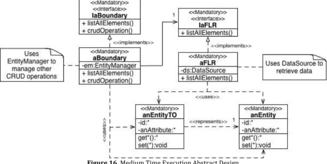
(3) List of Figures Figure 1. Use Cases of the SPL for Projects Management............................................................. 19 Figure 2. Use case patterns of the SPL of enterprise applications ................................................. 20 Figure 3. Use Cases of the SPL for Reference Management ......................................................... 21 Figure 4. General Process for product derivation ........................................................................... 22 Figure 5. Domain Metamodel......................................................................................................... 23 Figure 6. Domain Model example .................................................................................................. 24 Figure 7. QAs Variability Model.................................................................................................... 25 Figure 8. Relationships between DMM and QAs Variability Model ............................................. 26 Figure 9. Example of quality configuration impact on SPL for Project Management systems ..... 29 Figure 10. Software Design Patterns to promote quality levels ..................................................... 31 Figure 11. Macroarchitecture: Components view .......................................................................... 32 Figure 12. Microarchitecture of a Presentation Component .......................................................... 33 Figure 13. General Microarchitecture of Domain Components ..................................................... 35 Figure 14. Normal Time Execution Concrete Design .................................................................... 36 Figure 15. ListAll projects use case sequence diagram (Normal Time Execution) ........................ 36 Figure 16. Medium Time Execution Abstract Design .................................................................... 37 Figure 17. Medium Time Execution Concrete Design ................................................................... 38 Figure 18. ListAll projects use case sequence diagram (Medium Time Execution)....................... 38 Figure 19. High Sync Time Execution Abstract Design ................................................................ 39 Figure 20. High Sync Time Execution Concrete Design ............................................................... 40 Figure 21. ListAll projects use case sequence diagram (High Sync Time Execution) ................... 40 Figure 22. High Async Time Execution Abstract Design .............................................................. 41 Figure 23. High Async Time Execution Concrete Design ............................................................. 42 Figure 24. ListAll projects use case sequence diagram (High Async Time Execution) ................. 42 Figure 25. Security-Confidentiality Manager Concrete Design ..................................................... 43 Figure 26. Concrete Interactions with Confidentiality Component ............................................... 44 Figure 27. Creation of a project considering data encryption ........................................................ 44 Figure 28. Retrieving all projects considering data decryption ...................................................... 45 Figure 29. Security-Integrity Abstract Design ............................................................................... 46 Figure 30. Security-Integrity Concrete Design .............................................................................. 46 Figure 31. Authentication process considering Integrity (Account Lockout) ................................ 47 Figure 32. Role-Based Access Control Pattern .............................................................................. 47 Figure 33. Security-Authenticity Abstract Design ......................................................................... 48 Figure 34. Security-Authenticity Concrete Design ........................................................................ 49 Figure 35. Authorization sequence diagram ................................................................................... 50 Figure 36. Case Study Macroarchitecture - Users .......................................................................... 50 Figure 37. Case Study Macroarchitecture - Risks .......................................................................... 51 Figure 38. Case Study Macroarchitecture - Projects ...................................................................... 51 Figure 39. Case Study Microarchitecture - Users Component ....................................................... 52 Figure 40. Case Study Microarchitecture - Risks Component ....................................................... 52 Figure 41. Case Study Microarchitecture - Projects Component ................................................... 53 Figure 42. Case Study Microarchitecture - Authenticity Component ............................................ 53 Figure 43. Case Study Microarchitecture - Transfer Objects ......................................................... 54 Figure 44. Case Study Microarchitecture ....................................................................................... 55 Figure 45. Modifications to our DMM to handle UML transformation ......................................... 56 Figure 46. ATL transformation (code fragment) ............................................................................ 57 Figure 47. Executing the ATL transformation ............................................................................... 58 Figure 48. Xtend2 Template example ............................................................................................ 58. . 3 .
(4) Figure 49. Template groups ............................................................................................................ 59 Figure 50. Java class sections ......................................................................................................... 60 Figure 51. Contribution interface ................................................................................................... 60 Figure 52. Contribution .................................................................................................................. 61 Figure 53. Concretization example of Contribution interface ........................................................ 62 Figure 54. Delegation strategy ....................................................................................................... 63 Figure 55. Conflict resulted from two or more contributions to a same template section ............. 63 Figure 56. Delegation strategy based on contributions ordering .................................................... 64 Figure 57. Templates involved in our generation process and their grouping ............................... 65 Figure 58. Ids for each quality level concretization ....................................................................... 69 Figure 59. Example of using extendContribution function ............................................................ 69 Figure 60. Identifications for each contribution section ................................................................. 70 Figure 61. Contributions to Project's domain component (Data Encrypted and Normal Time Execution) .............................................................................................................................. 71 Figure 62. Mixed Contributions to Project's domain component (Data Encrypted and Normal Time Execution) .................................................................................................................... 71 Figure 63. Example of delegating contributions among Templates and Contributors ................... 72 Figure 64. Resulting contributions when an attribute is selected and when it isn’t ....................... 73 Figure 65. Generation Workflow ................................................................................................... 73 Figure 66. Using our API to enable quality handling ..................................................................... 74 Figure 67. DomainCodeGenerator implementation ....................................................................... 75 Figure 68. Product Derivation Process ........................................................................................... 77 Figure 69. Generation Plugin content ............................................................................................. 78 Figure 70. Using our DMM to create Domain Models .................................................................. 78 Figure 71. Domain Model of our Case Study................................................................................. 79 Figure 72. Properties of Domain Model elements.......................................................................... 79 Figure 73. QAs model using S.P.L.O.T. ........................................................................................ 80 Figure 74. QAs model Configuration ............................................................................................. 80 Figure 75. Generation Workflow Execution .................................................................................. 81. . 4 .
(5) ABSTRACT In software product line engineering, the customers mostly concentrate on the functionalities of the target product during product configuration. The quality attributes of a target product, such as security and performance, are often assessed until the final product is generated. However, it might be very costly to fix the problem if it is found that the generated product cannot satisfy the customers’ quality requirements. Several approaches have been proposed to deal with this issue, focusing on the assessment of a quality attribute of a product configuration to measure the impact on a quality attribute made by the set of functional variable features selected in a configuration. Nevertheless, these approaches are only interested in characterizing the relationships among quality attributes and product functionalities to provide useful information about predicting the quality of the target product, relying on the previous existence of the software components that provide such measures and values. Our approach provides a SPL that uses model-driven techniques to automate derivation of product line members, considering promotion of quality attributes during this process by means of software enterprise patterns. In concrete we provide the following contributions: i) a domain metamodel that enables defining functional scope of product line members, ii) a quality attributes variability model to handle definition of quality scope of product line members, iii) a Reference Architecture (characterization of software enterprise design patterns from the perspective of the quality attributes they promote or inhibit) to construct product line members that exposes explicit variation points related to quality attributes and their relationships with functional features, iv) and tool support based on a generation engine to automatically construct product line members, following the Reference Architecture constraints. An illustrative example based on a Project Management software product line is presented to demonstrate how the proposed approach works.. . 5 .
(6) 1.. INTRODUCTION. Today software engineers are faced with a demand for complex and powerful software systems, which must be developed in short, time. To solve this problem, software reuse was emerging as a principal key to a successful software development because of its potential to reduce the time to market, increase quality and reduce costs [1], as it consists in creating and in assembling systems with existing components. Software Product Line Engineering (SPLE) is an expanding approach, which aims at developing a set of software systems that share common features and satisfy the requirements of a specific domain [2]. While having much in common, products derived from a SPL still differ in certain requirements, design decisions, and implementation details. The variability stems from many sources such as customer’s specific needs, mutability of the environment, system maintenance and evolution, and so on. Product Lines are gaining importance in the software development field as they reduce development time, effort, cost and complexity and increase quality of products [3]. One of the challenges in today’s both traditional software engineering and SPLE approaches is to deliver high-quality software on time to customers [4]. Successful companies must have a focus on customer satisfaction and software quality to ensure that the desired quality is built into the software product and that customers remain loyal to the company. This is especially true for the IT industry where customers have everincreasing expectations of software quality. Software quality has become a major concern of software organizations [5]. A lot of research thus has been done to refine the concept of quality into a number of quality attributes (QAs), also known as quality characteristics, quality factors or non-functional requirements (NFRs), (see e.g., [6] [7] [8] [9]). QAs of the products, such as performance, and security are usually handled until the final product is produced and tested in the system-testing phase [10]. Different members of the software product line may require different levels of quality attributes. For example, one product may require a very high security whereas in another product security is not that important. If it is found that the quality attributes of the product fail to meet the customers’ requirements in a later product development stage, it is costly to fix the problems. Therefore, the QAs of a target product (level of accomplishment for each QA) should be assessed as early as possible in the product development process. Although there are studies that mention the existence and influence of QAs on the domain analysis and design (e.g., [11] [12] [13]), they do not consider their influence on SPL assets implementation. Zhang et al. [14] propose a Bayesian Belief Network (BBN) based approach to explicitly modeling the impact of variants (especially design decisions) on system quality attributes. Zhang G. [15] proposes an Analytic Hierarchical Process (AHP) based approach to estimate the relative importance of each functional variable feature on a quality attribute. Bartholdt et al. [16] presents an integrated tool-supported approach that considers both qualitative and quantitative quality attributes without imposing hierarchical structural constraints. Even though these works explicitly consider QAs variations and their relationships with functional features, they focus on characterizing such relationships to provide useful information about predicting the quality of the target product, relying on the previous existence of the components that . 6 .
(7) provide such measures and values. Thus, the design decisions and implementation details needed to construct these components in order to promote the configured quality levels are not considered. Such condition exposes limitations on current SPL approaches regarding strategies that systematically make use of good design practices to promote quality attributes in the core assets of the line, i.e. software components. More particularly, although there are several repositories that encompass the knowledge regarding how to design concrete architectures and components of a given application domain, taking into account quality concerns, i.e. Reference Architectures, current SPL approaches do not use a systematic mechanism to take advantage of this consolidated expertise to modify software component’s design structure and behavior, in order to promote different levels of quality. Our contribution in this work is to develop a strategy and tool support that, making use of software design good practices, allows a product line engineer to automatically derive products that are configured based on a set of functional and quality constraints. Specifically, we provide the following contributions: i) a domain metamodel that enables defining functional scope of product line members, ii) a quality attributes variability model to handle definition of quality scope of product line members, iii) a Reference Architecture (characterization of software enterprise design patterns from the perspective of the quality attributes they promote or inhibit) to construct product line members that exposes explicit variation points related to quality attributes and their relationships with functional features, iv) and tool support based on a generation engine to automatically construct product line members, following the Reference Architecture constraints. An illustrative example based on a Project Management software product line is presented to demonstrate how the proposed approach works. . 2.. BACKGROUND. 2.1. QUALITY ATTRIBUTES. Quality is the degree to which a system meets the Non-Functional Requirements (NFRs) in the context of the required functionality. Quality Attributes (QAs) are crosscuttingconcerns known as nonfunctional properties of a software system such as performance, safety, and security [17], [18]. Achieving QAs must be considered throughout the development process of a software system. According to Bass et al. [19], there are three problems related to QAs: the definitions provided for an attribute are non-operational (lack of preciseness), there is no clarity on which quality a particular aspect belongs to (overlapping attribute concerns) and each attribute community has developed its own vocabulary. A solution to the first two of these problems is to use quality attribute scenarios [20]. A solution to the third problem is to use a standard model that specifies each attribute underlying concerns, like ISO 25000 series [21]. A quality attribute scenario (QAS) serves as a mean of characterizing quality attributes, and consists of six parts [22]: i) the source of stimulus, which is the entity that generates the stimulus, ii) the stimulus, which represents an internal or external incentive that. . 7 .
(8) affects a part of the system and acts as a trigger e.g. a user invokes a function, iii) the environment, that represent the conditions under which the stimulus occurs, e.g. at runtime, iv) the artifact that identifies the system or a part of it that is stimulated, v) the response, which is the action that’s undertaken when the stimulus arises, and vi) the response measure, that provides numeric indicators so the quality attribute can be tested. An example of a QAS can be: An end user requests the system to retrieve data from a particular table stored in a local database. Such retrieval must take 4 seconds tops to display the information to the user. 2.2. SOFTWARE ARCHITECTURE. Software Architecture (SA) can be defined as the set of structures needed to reason about the software system, which comprises the software elements, the relations between them, and the properties of both elements and relations [23]. The importance of SA is that it serves as a blueprint that details the system that is going to be developed [24]. It must provide an alignment between user, business and system goals [25]. One of the most relevant contributions of SA is its role as primary carrier of system qualities such as performance, modifiability and security [22], [24]. It involves a series of decisions based on a wide range of factors that have considerable impact on QAs that decide the overall success of applications. Authors like Hollingsworth [26] and Vogel et al. [27] have found that to adequately reason about specific properties, the software architecture field must be divided into micro and macro architectural levels. Macro-architecture deals with top-level/high-level design issues, for instance, the spectrum to which architecturally relevant elements are assigned. It covers aspects such as requirements, decisions and structures at a high level of abstraction, for example, decisions with regard to important system interfaces, identification of system’s main building blocks and the relationships among them [27]. While macro-architecture deals with system’s overall structure [28], such as viewpoints, architectural styles and patterns, micro-architecture focuses on detailed structure and behavior of system’s components. Alur et al. [29] highlight that micro-architectures are building blocks upon which we build applications and systems, and that they can be seen as a prescriptive solution that uses different design patterns to solve larger problems concerning macro-architecture decisions. Micro-architecture is also known as software component engineering [26], which is closely related to the notion of reuse [30]. Some of the advantages of this particular area are the focus on component’s interoperability and the assurance of component’s promoted properties through proper design decisions. Such decisions focus on promoting quality attributes on each developed component, which provides a well founded and proven base to deal with system’s composition at macro-architectural levels, fomenting the construction of applications under a quality approach. Enterprise Software Applications (see section 2.3) usually are developed using proven architectural styles, such as the three-layer based architecture [29], which we are going to use as the fundamental structure to derive the products of our line. An architectural style defines a set of types of elements, types of relationships and constraints between them. . 8 .
(9) [22]. Software architects designing a solution using a style, must design the software using the style-specific types of elements and relationships, and respect the corresponding constraints. The Three-layer architectural style [29] [31] defines three layers: the presentation, logic and data-access layers. An application designed using this style includes these three layers. In addition, each layer comprises components with layer-specific types and responsibilities: the presentation layer comprises GUI components; the logic layer includes the components that implement the logic behind the business transactions; and the data access layer includes data-access components that store and retrieve data from files, servers and databases. 2.2.1. TACTICS. Knowing SA’s role as quality insurer, it is important to rely on mechanisms that aim to guarantee software quality on both macro and micro levels. Such mechanisms rely on design decisions and are known as tactics. Clements et al. [32] and Rozanski et al. [33] determine that a tactic is a widely used architectural approach that has proven to be useful to achieve a particular quality. For example, “rollback” is a tactic to recover from a failure aiming to increase a system’s availability, or “concurrency” is a tactic to manage resource access aiming to improve performance. Among these tactics, Design Patterns [34] are a well-know mechanism to achieve QAs at a micro level, i.e. component’s internal structure. According to Gamma et al. [34], a design pattern is a recurrent situation that must contain four essential elements: a pattern name, the problem that determines when to apply the pattern, the solution that states how the elements provided by the pattern should interact and function to solve the problem, and the consequences that take place when the pattern is applied, such as results and trade-offs. Design patterns catalogs must contain a set of design patterns that are useful in a particular context. Every pattern contained in the patterns catalog must contain at least these four elements to describe its use. There are many patterns catalogs in the literature. Steel et al. [35] and Hafiz M. [36] provide catalogs that focus on improving applications security. Fowler M. [31] provides a list of design patterns used in ESAs. Bien’s book [37] provides a set of design patterns that result as an evolution from previous patterns specified in [29]. These patterns are intended to be use in the context of ESA developed using Java Enterprise Edition-JEE [38]. The book maintains tiers division provided in [29] and elaborates on the details and main changes of deprecated patterns and newly ones. Each pattern contains the four elements described by Gamma et. al, plus a section that highlights non-functional attributes that are affected by them. It also proposes two configurations to properly use the patterns catalog depending on application objectives: service oriented and domain-driven architectures. Each configuration summarizes a pattern language that declares some constraints to include or exclude different patterns. Bien’s 2012 book [39] offers and update to his earlier catalog in terms of new discovered patterns and modifications to some previous patterns intends and uses. It provides an extensive set of enterprise patterns that meet the following characteristics:. . 9 .
(10) i) are currently used in real enterprise applications, ii) provide the basic elements listed by Gamma et. al., iii) each pattern briefly describes how it affects particular quality attributes and iv) the catalog is focused to be used in enterprise applications, which is our context of work. Adam Bien is a well-known java developer and architect that have participated in the edition of several books related to Java technology [40]. He holds numerous titles that certificate his expertise in using Java for enterprise IT projects, between them Java Champion [41] and Java Developer of the year 2010 [42]. His contributions vary from the organization of Java related workshops [43], two books about the use of Java in the development of enterprise applications (the referred above among them), a constantly updated blog about Java topics and implementation issues of his proposals [44], and a TV channel addressing the same concerns [45]. Bien also provides a repository 1 that consolidates a collection of implemented samples and reusable templates, which demonstrates patterns, approaches and architectural ideas for the Java EE 6 platform. Besides design patterns, there are several other tactics that attempt to ensure quality attributes in enterprise applications. For instance, Kalinsky D. [46] list a set of design patterns for high availability that can be applied to system’s infrastructure, like hardware redundancy. Microsoft [47] provides server-clustering pattern to address performance, scalability and availability of enterprise applications. Specifically, load-balanced cluster allows distribution of network traffic between several physical servers to improve application’s performance, while fail over cluster proposes hardware redundancy to deal with server damage and unavailability. 2.2.2. REFERENCE ARCHITECTURES. RAs go one step further in reuse of best practices in architectural design [48], [32]. Nakagawa et al. [49] define a RA as: “an architecture that encompasses the knowledge regarding how to design concrete architectures of systems of a given application domain; therefore, it must address the business rules, architectural styles (that address quality attributes in the reference architecture), best practices of software development (for instance, architectural decisions, domain constraints, legislation, regulations, and standards), and the software elements that support the development of systems for that domain. All of these must be supported by a unified, unambiguous, and widely understood domain terminology”. RAs importance is that they provide consolidated information about a particular domain to serve as guideline to build specific products taking into account best practices and quality constraints. RAs become a main asset to develop software applications, because they provide consolidated information of the most relevant components of a particular domain. A RA provides structure, identification and relationships of the main components of a particular software architecture that can be reused to build a concrete software application, serving as support at a macro architectural level. This information may be expressed in terms of architectural styles or patterns using a standard modeling language like UML. RAs must 1 https://kenai.com/projects/javaee-‐patterns . . 10 .
(11) also contain information related to quality attributes, that is, tactics. Such information may vary from infrastructural decisions to software design decisions. Software decisions include definition of guidelines, standards and templates to address common problems of the related domain. The use of design patterns to describe component’s internal composition and behavior (micro-architecture) is also an important contribution that RAs provide, as they consolidate relevant information to develop components aligned to inherent domain quality attributes. As stated before, there are several elements that compose a RA, so it is important to have means to adequately represent a RA, because they are required to be understandable for wide variety of stakeholders (such as customers, product managers, project managers, and engineers). Nakagawa [50] summarizes several works that have focused on the properly representation/description of RA; these methods include semi-formal techniques of UML (Unified Modeling Language) [51], and ADL (Architectural Descriptions Languages) and their extensions [52]. 2.3. ENTERPRISE SOFTWARE APPLICATIONS. The context or domain of this work is focused on Enterprise Software Applications (ESAs). These types of applications are intended to satisfy the needs of entire organizations. In [31], Fowler M. identifies that an ESA usually involves persistent data, concurrent user access to the information and several user interfaces to handle the big amount of data requested. This type of software requires abstraction and modeling of how organizations work; besides, it requires development tools that support such model in order to build unique appropriate applications that match organization’s needs. ESAs must accomplish a certain set of characteristics, for instance, [53] defines ESAs as network applications that must be large-scale, multi-tiered, scalable, reliable, and secure. These non-functional characteristics ensure ESAs quality. Bass et al. [22] agree that this type of applications must be oriented to a web-based environment (network apps) and that they must fulfill a minimum set of quality attribute requirements to ensure quality, between them scalability, availability/reliability, security, usability and performance. Sections below describe the domain metamodel that we use to limit the scope of particular ESAs that we are interested in. There are standards that emphasize on providing an environment that ensures all of these characteristics, allowing developers to focus on relevant business information, such as its logic and functionality. Java Enterprise Edition [38] is one of these solutions. It provides latest technologies integration and support to maximize web based enterprise applications development and management. There are other solutions like JBoss Application Server [54] that also provides integrated tools to ease enterprise applications management. The selection of one these solutions depends on organization’s specific needs and technical knowledge. 2.4. MODEL DRIVEN ENGINEERING. As technology evolves, several platforms for software development have been developed. These platforms are usually heterogeneous, that is, despite offering similar interfaces, each one has its own operational standard and a specific set of base components. This. . 11 .
(12) implies that it is mandatory to know the characteristics of the selected platform prior the software development process, in order to use the basic functionality it provides. Hence, once the new application components are built, this software will only run on the selected platform and won’t be compatible with other technologies. As a concrete example of the above situation, we find Java and .NET platforms, which provide a set of basic components that facilitate application development. These basic components provide functions or tasks that simplify software development. However, once an application is built using the basic components of any of the two platforms, it can only be executed on the selected platform. This implies that an application developed under Java platform cannot run on .NET platform and vice versa. Model Driven Software Development (MDSD) represents a new approach in software engineering that deals with the inability of third generation languages to manage heterogeneous platforms, plus it provides effective expression of domain concepts [55]. MDSD does not attempt to solve the problem of heterogeneity by unifying platforms. Its goal is to support software development independently of the technology used. Thus, decisions of platform selection and implementation details are postponed to final stages of the development process. In order to achieve his goal, MDSD raises the level of abstraction, using models as first-class elements, i.e. assets that can be processed by a computer or by a tool. This is the main feature that differentiates MDSD from traditional approaches of software development where models are used exclusively for documentation purposes. Models deal with a high degree of abstraction, representing the concepts that are relevant to a particular domain. This enables focusing in the representation of the problem rather than its implementation, reducing software development complexity through the separation of different concerns in multiple views. Thus, MDSD can express both the problem and the solution across different models, each one representing a specific point of view, thereby reducing the complexity of developing and managing heterogeneous platforms, since the software can be expressed in terms of domain concepts. In order to increase the level of abstraction, each model must be defined in terms of a specific language. In general, these languages are defined in terms of domain particular concepts without considering implementation details. The definition of a language involves abstracting its domain concepts, a proper notation and rules that must be met. Thus, a model is constructed in terms of the language of its metamodel, implying that the metamodel is responsible for abstracting these domain concepts and rules. In conclusion, metamodels are models that represent concepts of a domain and the relationships between these concepts. The relationship between a model and the metamodel is known as a conformity relationship [56]. Thus, it is said that a model conforms to a metamodel if it meets the description and restrictions of the metamodel. As explained above, MDSD uses models as first-class elements, i.e. assets that can be processed by a computer or a tool. In order to process these models, it is necessary to use languages that enable specifying the required inputs; the operations performed and the. . 12 .
(13) output elements. The specification of these operations is known as model transformation. Transformations between models are composed of transformation rules, which are defined in terms of the domain concepts (metamodel) involved in the transformation [57]. Each transformation rule defines a set of inputs, a set of operations and a set of output elements. Both inputs and outputs may be specified in source and target models of the transformation. There are different kinds of transformations classified by the nature of their source and target domains. Most common transformations are: model-to-model and model-to-text. Former implies turning a source domain model into a target domain model, latter enables using a domain model to create text. This type of transformation is generally used to generate source code and configuration files. 2.5. SOFTWARE PRODUCT LINE ENGINEERING. Product line engineering is a paradigm that places component production and the reuse strategy at the center of the development process [58], [59], intended to allow the development of several applications that share common aspects. SPLE put into practice this paradigm in software context. This discipline is divided in two main phases, named domain engineering and application engineering [60]. Former phase identifies domain applications, distinguish between their similarities and variations and structures this information. Latest phase consist of the efficient production of the applications defined in the first stage, using a production plan as a guideline to successfully configure each application. Domain engineering phase deals with identifying and documenting SPL scope, which is known as domain, plus it must deal with variability management. The first activity is the identification of the commonalities of the SPL domain, which are the characteristics that will be shared by all the products of the product line. This stage also has to deal with the identification of variation points, which are the specific points of the SPL domain that allow derived product’s customization. Each variation point requires defining all its possible variants. A variant is a characteristic that isn’t necessary contained in every derived product of the line. An asset known as the variability model consolidates identified characteristics and defines their relationships. There are several notations to define the variability model; between them, [61], [62] and [63] propose feature models (FMs); [64] suggest enriched UML diagrams; [65] add model-engineering notations; [66] propose a variability language; [60] presents Orthogonal Variability Model (OVM). Once the variability model is defined, a specification shared by all domain products must be set. The product line architecture (PLA) is an asset preplanned to support their common basis, variations and architectural requirements. It must capture the entire set of features of the SPL, its variability model, and must define assembly rules and constraints (using a formal notation) that allow the generation of particular products. According to Clements P. [59] and Bass et al. [19] the PLA is the original artifact of the reusable artifact kernel, and thus must be a main development objective. There is some controversy on the subject of differences between the concepts of RA and PLA. Most authors, including [67], [68] see no real differences between the two, but others see differences in the abstraction level and domain type. For instance, Nakagawa. . 13 .
(14) et al. [69] establishes a relationship between this two concepts: while reference architectures deal with the range of knowledge of an application domain, Product Line Architectures (PLA) are more specialized, focusing sometimes on a specific subset of software systems of a domain and providing standardized solutions for a smaller family of systems. This means that a RA can be specialized into many PLAs. Angelov et al. [70] agree with the previous definition stating that product line architectures are less abstract than RA, but more abstract than concrete architectures. Variability management must also allow construction of product line members. Approaches like [67] state the use of decision models [71], [72], [73], [74] to capture external variability and define the concrete resolution during the derivation of products [72]. Each decision maps each variation point defined in a variability model with its possible resolutions (i.e. components), in order to define how core assets must be adapted and assembled, aiming to realize corresponding related variation. Application engineering phase focuses on configuration and derivation of product line members; according to the main assets produced in domain engineering stage and a production plan [67]. The configuration consists of selecting a consistent and full set of variants from the variability model. Product derivation deals with the manual or automatic activities that constructs the final product from a functional configuration, reusable elements, and in accordance with the production plan. There are several approaches that focus on the automation of product creation from decision and resolution models. Dhungana et al. suggest DOPLER, an approach entirely based on decision models for deriving the products in a line [75]. The AMPLE project [76], with the TENTE approach, has proposed a quasi-automatic derivation of the product line from the features model and a features-oriented language. Lastly, model-oriented approaches such as [77] and [78] consider methods for expressing the use of reusable elements in the realization of a selection of features. Voelter et al. highlight in [3] that it is possible to build product lines of product line architectures. They refer to this property as Meta-Product Lines. This means that the domain models that result from a particular domain metamodel are used as variability models to configure independent SPLs i.e. each domain model enables configuration of several products by selecting/deselecting domain concepts that are wanted on a target product; instead of being used as particular products i.e. each domain model is a target product. In this work we provide a domain metamodel that is used as a Meta-Product Line for constructing ESAs, within the scope of domain concepts and relationships defined in it. 2.6. RELATED WORK. Due to there is a wide range of QAs that can be considered in SPL development, i.e. ISO’s 25000 classification, addressing all of them might end up in several interrelated constraints and conditions, making the derivation of products a difficult and error-prone task to achieve. Thus, it is important to identify the most frequent QAs that the community is interested in. Works like [15] [14] [79] identify performance, usability, security and cost as the quality attributes that are of frequent interest to final users.. . 14 .
(15) After identifying these QAs, a proper way to model them (contemplating their variations) is needed. The idea of variations in quality is considered in different works [11] [12] [13] and there are also some approaches that address variability modeling taking into account quality attribute variability. However, “there is a lack of thorough understanding of existing approaches to be able to integrate quality attribute variability as a part of the systematic variability management of software product lines” as proposed by [11]. A survey presented in [80] summarizes several existing methods that address quality attribute variability specification and managing. Approaches like Goal-based model [81] propose to treat and model non-functional requirements or QAs as soft goals, so they represent conditions or criteria that the system should meet. Benavides et al [82] [83] propose to extend feature model to deal with extra-functional features. They propose a notation extending feature models with attributes, characteristics of a feature that can be measured such as availability, cost, latency, bandwidth and relations among attributes. Work in [15] uses feature models to represent QAs, where the leaf nodes of such quality tree determine the quality that the SPL will assess, because they have sufficient semantics for the impact-relationships between quality attributes and functional variable features analysis. This decision is due to quality attributes that are represented at high levels in a feature model are often vague and inherently hard to measure, such as performance or security. Work presented in [15] highlights the importance of dealing with quality issues in early stages of the product development process, such as considering impact of quality constraints to the final products from the start. Besides gathering several approaches for specifying variation in quality attributes in SPL, Etxeberria et al. [80] emphasize on the techniques that they use to relate functional variability with quality variability. Goalbased models use correlations to represent the links among functional and soft goals. Each correlation links is marked with an influence qualitative label (++, --) that is converted to a qualitative value to be used in a later quality analysis. Zhang et al. [14] proposed a Bayesian Belief Network (BBN) to capture the impact of functional variants on quality attributes. They link functional requirements to quality attributes using noted definitions that are relative to each domain, i.e. “high performance” definition might mean a response time lower than 0.5 seconds to one domain and less than 1 seconds to another. After all links are defined, conditional probability is used to quantify the conceptual relationships. Notice that these models assume that the quality levels are affected by the functionalities selected, and not in the opposite direction. Several works consider QAs in SPL development. For instance, Huerta et al. [84] provide support, applying model-driven engineering principles, to the identification and representation of non-functional requirements (NFRs) in SPL development, also offering a mechanism for the validation of their fulfillment through the association of measures, thresholds and OCL constraints to each NFR. They provide a meta-model that allows definition of NFRs based on ISO 25000’s [21] quality model to define measures for a specific quality attribute, besides the impact that such attribute might have on features or core assets (i.e. positive/negative). Their model also allows definition of variability for a. . 15 .
(16) particular QA, i.e., performance may have different acceptance thresholds depending on system’s configuration. They determine that a NFR may be related to many QAs, for instance, reliability can be broken down into two QAs: availability and fault tolerance. Each NFR must define a restriction that determines its achievement; such restriction is defined using OCL. Once NFRs are defined and related, an automatic OCL validation is performed taking as input this configuration model to check whether the different constraints are satisfied or not. Such validation concludes whether a product/artifact promotes or inhibits the associated NFRs. This work focuses on providing means to adequately relate and measure NFRs impact on features/artifacts; thus, they rely on the specification of such measures to operate. They do not care about component’s design decisions to determine how they affect QAs, nor provide mechanisms to automate their generation. Gürses expresses NFRs in [85] through qualitative goals. This approach allows performing trade-off selections among different types of basic NFR-goals, returning the configuration that fulfills those goals. The modeling of NFRs is done using an extended feature model that is annotated with quality information. Sagardui et al. defined a method for capturing the quality variability and the relationships among functional variability and quality aspects through an extended feature model that allows the expression of quality attributes, their variability and the relationships (impacts) that features or feature groups have on the quality attributes [86]. Both proposal focuses on modeling variability of quality attributes and relating such variability to functional characteristics of the SPL. They also provide means to evaluate accomplishment and trade-offs between quality attributes for a particular configuration of the SPL. However, their proposals only introduce quality considerations to SPLE, hence they do not focus on how such identified and related QAs are going to be fulfilled, i.e. using design patterns for their construction. Work in [14] proposes a Bayesian Belief Network based approach to address the problem of analysis and prediction of quality attributes for a product line. They use BBN to capture the design knowledge and experiences of domain experts. Such approach enables graphically modeling the impact of design decisions on quality attributes, by using nodes and relationships among them. After capturing the qualitative relationships among variables (denoted by nodes), a quantification process takes place, where a conditional probability is assigned to each node in the BBN. Having quantified the graphical model, a quantitative analysis can be performed (e.g., predicting the quality of the target system). The proposal in [15] uses an Analytic Hierarchical Process (AHP) based approach to estimate the relative importance of each functionality on a quality attribute. They conclude that based on the relative importance value of each functionality on a quality attribute, the level of quality attributes of a product configuration in software product lines can be assessed. To do so, they identify the relevant functionalities that impact a quality attribute; they estimate the relative importance value of functionality identified on a quality attribute, they calculate an importance value for a product configuration on a quality attribute (e.g. 1 for Equal Importance: Two elements contribute equally to the objective, and 7 for Very Strong Importance: One element is favored very strongly over another), and they define a representation scheme for quality attributes in feature models that enables measuring quality levels for a particular product. [16] provides an integrated. . 16 .
(17) tool-supported approach with both qualitative and quantitative quality attributes that are explicitly considered in the product derivation process without imposing structural constraints such as a hierarchical structure. This tool enables configuring a product relating each functionality to the quality attributes it promotes or inhibits. These relationships are quantified in order to enable calculating the resulting value of a quality attribute for a particular product, to determine weather the product satisfies the quality needs of the customer. Even though these works explicitly consider QAs variations and their relationships with functional features, they focus on characterizing such relationships to provide useful information about predicting the quality of the target product, relying on the previous existence of the components that provide such measures and values. Thus, the design decisions and implementation details needed to construct these components in order to promote the configured quality levels are not considered. Dealing with code generation, there are several technologies to manage templates, e.g., Xtend22, Acceleo3. Former is designed as a successor of Xpand. However, it is not tailored specifically to code generation but as a general-purpose language that is nicely usable for code generation as well. The use of Xtend2 demands providing an engine (source code) that drives the generation, although it is possible to use Modeling Workflow Engine for this purpose. Latter is more tailored for simple code generation. Its syntax is based on an OMG specification for code generation, and provides a fullfeatured IDE for developing code generation. Difference between these tools is that Acceleo is limited to work only with particular models (EMF), while Xtend2 permits using other data sources, providing an easy way to call any Java code available.. 3.. CASE STUDY. To illustrate our approach, this section presents a case study on a SPL of enterprise software applications, a product line with functional and quality variability. Given that this SPL must support configuration of several product line members (SPLs) to derive different ESAs, we elaborate on the description of a SPL for Project Management systems. This description serves as an exemplification of the kind of software product lines that can be derived from the SPL of enterprise software applications. The SPL for Project Management systems supports a variety of functionalities for management of projects, risks and users. In addition, it supports variations in the quality attributes each product must exhibit in order to offer different products to medium and big companies. Following, we will describe its functional variability, which is a set of optional and mandatory functionalities that the SPL offers. This SPL must always allow the authentication of users against the system, using a login and a password. Once the user is authenticated, the product line might provide the following super set of functionalities to users: -. List all the users registered in the system Register new users in the system. 2 http://eclipse.org/xtend/ . 3 https://eclipse.org/acceleo/ . . 17 .
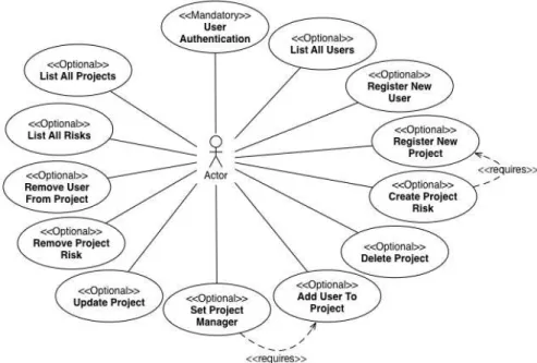
(18) -. Register new projects in the system Update the information related to a project of the system Delete projects from the system Add users to projects, in order to indicate the members of each project Remove users from projects, in case a user is no longer a member of a project Create project risks. Notice that risks existence depends on a project’s existence Remove risks from projects Set a project manager from the users related to a project. Notice that this functionality requires the addition of users to projects List all the risks of a project List all the projects registered in the system. Every project must have an id (serial number), a name, a description and a start date. Each registered user must have an identification number, a name, a cellphone number and a password. To identify risk, each one must provide an id (number), a name, a description, an impact (decimal), a probability (decimal) and the identification of the project it belongs to. These functionalities are usually modeled as use cases that can be included in the application during application engineering. These use cases can be modeled [87] [88] including stereotypes such as <<Mandatory>> and <Optional>> to represent if the use case must be included in all the products or might be included in one particular product. We also use the <<requires>> stereotype to indicate that the selection of a use case demands the selection of the use case it requires. Figure 1 shows the functional variability of the SPL for Project Management systems in terms of use cases. The <<requires>> dependency between “Create Project Risk” and “Register New User” use cases indicates that a risk cannot be created unless the project that it belongs to is created first. The <<requires>> dependency between “Set Project Manager” and “Add User To Project” means that a project can only set its manager as long as it has users associated to it. Thus, the project manager has to be one of these related users. Notice that many products for Project Management might be configured, by selecting several optional use cases.. . 18 .
(19) Figure 1. Use Cases of the SPL for Projects Management. Figure 1 presents the SPL for Project Management systems as an example of a software product line that can be derived from the SPL of enterprise applications. Some authors like Robert B. identify use case patterns [89], which are recurrent user intentions and system responsibilities that are present in several systems. We use this concept in order to abstract and group the functional scope of the SPL of enterprise applications. Our proposal includes the following use case patterns as part of the functional scope we can reach. Figure 2 summarizes these use case patterns, which conform the functional scope of the SPL of enterprise applications. -. List all elements from a business entity. This abstraction applies to the use cases: List All Projects, List All Risks and List All Users, where the business entity abstraction might be concretized into Project, Risk and User. This use case pattern refers to retrieving all instances of a particular business entity.. -. Create a master business entity. This abstraction is used in the uses cases: Register New User and Register New Project, where master stands for an entity that is self identified and do not depends on the existence of others to be created [90] [91]. The business entity abstraction might be concretized to Project and Risk.. -. Create a detail business entity. This abstraction applies to the use case: Create Project Risk, where detail stands for an entity that depends on the existence of another entity to be identified and created [90] [91], which is specified by the <<requires>> stereotype. The business entity abstraction in this case is concretized into Risk.. -. Delete a master business entity. This abstraction applies to the use case: Delete Project, where the business entity abstraction is concretized into Project.. . 19 .
(20) -. Associate two master business entities (One to Many fashion). This abstraction is used in the use case: Add User To Project, given that both business entities User and Project are masters and a relationship between them is created, where one project may have many users associated.. -. Associate two business entities (One to One fashion). This abstraction applies to the use case: Set Project Manager, given that it relates one User to one Project. This association has the particularity that it may only be established from a previous existing “one to many” association between the same entities. This constraint is represented by the <<requires>> association, e.g. a project can set its manager as long as it has users related to it (the manager must be one of these users).. -. Update a master business entity. This abstraction is used in the use case: Update Project, where the business entity abstraction is concretized into Project.. -. Delete a detail business entity. This abstraction applies to the use case: Remove Project Risk, where the business entity abstraction is concretized into Risk.. -. Disassociate two master business entities (One to Many fashion). This abstraction applies to the use case: Remove User From Project, given that both business entities User and Project are masters and an existing “one to many” relationship between them will be eliminated.. -. Authentication of a business entity. This abstraction is used in the use case: User Authentication, where the User entity provides the information to be used in the authentication process. This use case pattern must be particularized for one and only one business entity, i.e. User entity only.. Figure 2. Use case patterns of the SPL of enterprise applications . . 20 . .
(21) Notice that this super set of use case patterns can be used to configure several SPL of enterprise applications. For instance, figure 1 shows how these use case patterns are concretized to create a SPL for Project Management systems. Another customer might be interested in configuring a SPL for Reference Management systems, where the functionalities are creation/deletion of Authors and Books, allowing relating these two concepts. Figure 3 depicts the functional variability of this SPL in terms of use cases.. Figure 3. Use Cases of the SPL for Reference Management. . The software product lines derived from the SPL of enterprise applications must also consider quality variability, such as levels of performance and/or security. This issue will be addressed in section 4.3.2.. 4.. PROPOSAL. Our contribution is a approach and tool support that, making use of software design good practices, allows a product line engineer to automatically derive products that are configured based on a set of functional and quality constraints. To do so, we provide a Domain Metamodel to deal with functional variability, we propose a features model to address non-functional (quality) variability; we mapped each variant of the quality model with enterprise Java patterns that promote the related quality attribute, and we developed a generation engine that takes a model from our domain metamodel and a configuration of our quality model as inputs to generate a product that satisfies such constraints. Following sections explain these steps in detail.. GENERAL PROCESS FOR PRODUCT DERIVATION In order to derive product line members by using our proposal, a series of steps must be performed. Figure 4 depicts the process we designed for product line engineers to create SPLs. The first activity is concerned to define the product line scope, which we separate in functional scope and quality scope. This includes relating functionalities and quality attributes in order to determine how quality decisions impact the implementation of product functionalities. Once the scope has been set and the required relationships have been determined, the software design process of product line members begins. For that, as part of our generation engine, enterprise design patterns are selected according to functionality and quality attributes previously defined; such design patterns are used to. . 21 .
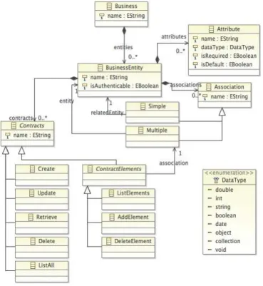
(22) design applications according to our controlled and pre-set Reference Architecture. Finally, code generation is performed, coupling design decision incrementally.. Figure 4. General Process for product derivation. . 4.1. DEFINE THE SOFTWARE PRODUCT LINE SCOPE 4.1.1.. FUNCTIONAL SCOPE DEFINITION. The first activity that a product line engineer must perform to use our proposal is the definition of the functional scope of the line to be configured. To do so, we presented in figure 2 a super set of use case patterns to enable configuration of product line members. Parting from this, we have taken and adapted a Domain Metamodel (DMM) from our previous work [92] in order to represent the use case patterns our strategy involves. The metamodel captures the variability in terms of business entities and their relationships, enabling managing functional variability for enterprise applications that involve CRUD operations over business entities, considering Master-Detail (One to Many) and “One to One” relationships between them. Creating a domain model according to this domain metamodel determines the functional scope of the product line member to be configured. The concepts involved in the domain metamodel are explained below. Figure 5 shows the domain metamodel. -. Business. Represents the identification of the SPL that is going to be configured. This identification must be provided as the name of the Business concept, i.e. “Project Management SPL”.. -. Business Entity. Represents a main concept of the business that stores data values and expose them through properties; they contain and manage business data used by the products derived from the SPL, i.e. Project, User and Risk. The name property acts as a label for the Business Entity, while the isAuthenticable property says whether the entity will be used as the authentication of the SPL or not.. -. Attribute: Every Business Entity has many attributes. An attribute contains particular information related to an entity, i.e. Project name and start date. Each attribute specifies its type, which can be any of the values exposed by the DataType concept, and it must indicate weather it is required (i.e. needs a particular value or can be null) and if it’s the identification of its container (BusinessEntity).. -. Association. Business entities might be related in two ways: “one to one” and “one to many”. SimpleAssociation concept represents a “one to one” association, where the relatedEntity relationship indicates the associated entity, i.e. Project’s related entity is User. MultipleAssociation concept represents a “one to many” association, which is a Master-Detail association, where the entity relationship indicates the entity that plays the Detail Role, i.e. Project’s detail entity is User.. . 22 .
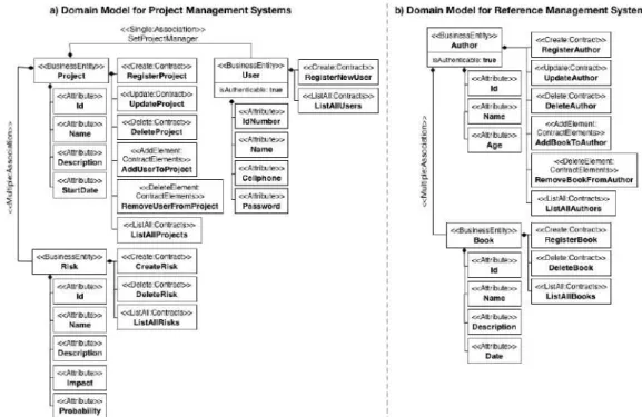
(23) -. Contracts. This concept specifies the operations or services that a Business Entity exposes. Such operations are CRUD related, i.e. creation, updating, deletion and retrieval of Projects. ContractElements are a particular type of Contracts that determine the operations that can be performed within a Master-Detail relationship, such as addition and deletion of details to a master, i.e. add users to a project.. The following restrictions and conditions must be taken into account, in order to properly use the Domain Metamodel: 1. There must be one and only one Business Entity with its isAuthenticable attribute set to true. This is due to the authentication of the SPL that must be realized with only one entity. 2. Authenticable Business Entity must define a password Attribute, which is required in the authentication process. 3. Master Business Entities are the ones that own one or many Associations of type Multiple. 4. Detail Business Entities are the ones that do not own any Association. 5. Each Association must have one and only one owner. 6. Every Business Entity might have at most one Contract of each type, i.e. one ListAll Contract only.. Figure 5. Domain Metamodel . . Figure 6a presents a domain model that corresponds to the functional scope of the SPL for Project Management systems presented as use case diagram in figure 1. Figure 6b depicts the corresponding domain model of the functional scope of the SPL for Reference Management systems presented as use case diagram in figure 3. . 23 .
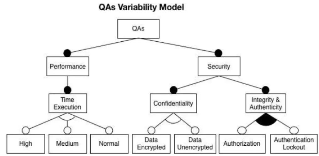
(24) Figure 6. Domain Model example . . If a product line engineer is interested in extending the domain metamodel to support a wider range of operations for the product line members, he/she may analyze the use cases involved in the target product line members, searching for similar characteristics among them that might be generalized or taken to a higher level of abstraction, allowing the identification and declaration of abstract use case patterns that are particularized depending on business functional requirements. Then, the newly use case patterns must be mapped into domain concepts e.g. business entities, so they can be included in the domain metamodel. 4.1.2.. QUALITY SCOPE DEFINITION. The products we are able to derive using our approach must satisfy the functional needs of the customers as well as have the desired quality attributes. Thus, the product line engineer must define the quality scope of the SPL of enterprise applications. Our approach enables defining the quality scope in terms of QAs, particularly, two of them, performance and security. ISO 25010 defines performance as “the degree to which the software product provides appropriate performance, relative to the amount of resources used, under stated conditions”. It is specialized into Time Behavior, Resource Utilization and Performance Efficiency Compliance. We focus on the first one, which determines the degree to which the software product provides appropriate response and processing times and throughput rates when performing its function, under stated conditions. On the other hand, security is described as “the protection of system items from accidental or malicious access, use, modification, destruction, or disclosure”, and it is specialized into 6 attributes. We consider 3 of those 6: Confidentiality, Authenticity and Integrity. The first one is related to protection from unauthorized disclosure of data. . 24 .
(25) or information, whether accidental or deliberate, the second one deals with proving the identity of a subject or resource, the third one ensures completeness of the data by avoiding modifications in an unauthorized or undetected manner. We use feature models to represent QAs like the work presented in [15], this help us to avoid depending on specific tools for modeling. Figure 7 depicts our QAs variability model.. Figure 7. QAs Variability Model. . -. Performance: Related to the response time (time execution) of database operations, in particular, retrieval of several records of a table (entity). This QA provides the following levels: o Normal: Refers to achieving response times equivalent to the provided by the database system. We will call such time X1. o Medium: Refers to achieving lower response times than the ones offered by the database system. Let X2 be the medium performance time; the condition X2 < X1 will always occur. o High: Refers to achieving lowest possible response times for data retrieval. Let X3 be lowest possible response times; the condition X3 < X2 will always occur.. -. Security: Related to protecting access, use, modification and/or disclosure of the system items. This QA is specialized into the following QAs: o Confidentiality: Provides a protection to the system data by encrypting it before it reaches the database. This QA provides two levels: one to indicate that the system data must be encrypted, and another one to indicate ignoring of data encryption. o Integrity: Refers to proving the identity of a subject that tries to access the system. This QA provides an optional level that enables blocking an account when several failed login attempts occur. o Authenticity: Provides proper authorization to users when they try to access/modify the system data. This QA provides an optional level that enables the system to provide a type of access control to its functionalities. . Notice that every QA is a mandatory feature. Such conditions occurs because as said in [93], functionalities can be definitely involved in or removed from a product of the SPL, . 25 .
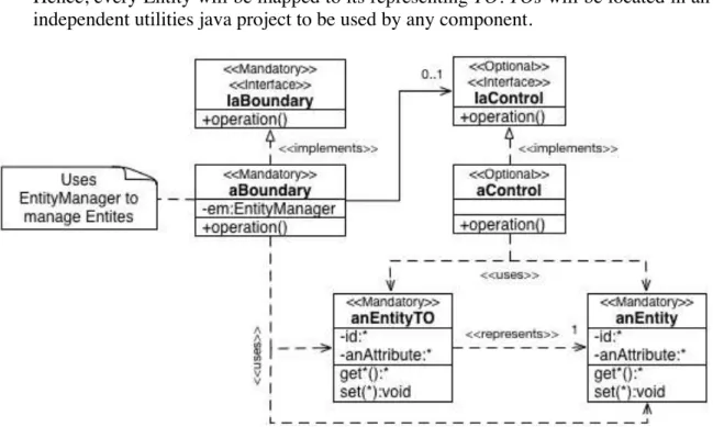
(26) but an QA can never be said to be involved or removed but only high or low in the degree of its effectiveness. Therefore, we can still consider QAs from a realistic viewpoint, that is to say a QA can be seen as not concerned if no special consideration is needed for it. Time Execution and Confidentiality QAs are exclusive grouped features, meaning that only one level of them can be selected at a time. We also decided to group Integrity and Authenticity QAs to illustrate an inclusive grouped feature. Such QAs can be modeled as separate QAs as well. 4.1.2.1. RELATE THE DMM WITH THE QAS VARIABILITY MODEL By using our approach, product line engineers accurately model the impacts of functional variants on quality attributes and vice versa. These impact relationships are indispensable to take the most adequate decisions during design and derivation of products to promote the required quality levels. Our concern with these relationships is to make explicit how software design practices are used to promote desired quality levels. Thus, in essence, we seek to recognize which QAs affect the implementation of the functionalities of our SPL and how they do it. We part from the premise that functionalities from the Domain Metamodel are affected by the QAs contained in the QAs variability model. That means that functionalities may vary their implementation depending on the desired quality level. We decided to use syntax similar to BBNs [14] to represent these relationships, but we do not consider quantification of them, given that we are interested in identifying and using design strategies to promote desired quality levels and not in measuring them. Figure 8 depicts these relationships.. . Figure 8. Relationships between DMM and QAs Variability Model. Given that ListAll Contract from our Domain metamodel reefers to the operation of retrieving the entire records of a Business Entity (which is mapped to a table in the database), and that we defined Time Execution as the response time of database operations, in particular, retrieval of several records of a table (entity), the selection of a Time Execution level directly affects the implementation of the ListAll operation.. . 26 .
Figure

+7


Documento similar
P7 Empirical quality Physical representation Physical representation K1 Perceived model-domain appropriateness Domain knowledge Model knowledge K2 Perceived ontological quality
Since effectiveness and playability are evaluated in the final product there is a need to provide quality assurance methods that incorporate quality issues from the early stages
ISO/IEC 25000 is composed of several parts: ISO/IEC 25040 4 defines the process of evaluating software prod- uct quality, and ISO/IEC 25010 5 determines the software
CVL (Common Variability Language) is a language for specifying variability in a way that is common to DSLs [10]. The main concepts in CVL are substitutions. Model
Our contributions are as follows: i) we present an accurate analytical model that is able to predict the energy consumption, ii) we present an approximate model that sacrifices
This booklet includes top tips for those who experience a mental health condition to help improve their quality of life and think about their sense of belonging and place in
Therefore, in this research service quality comprising the secondary dimensions physical quality, product quality, staff behaviour and responsiveness, is considered as an
To build the training sets to learn how to assess the quality of food products, we must first represent the relevant attributes involved in perceiving product con- ditions..
