energies
Article
Advanced Control Strategies of Induction Machine:
Field Oriented Control, Direct Torque Control and
Model Predictive Control
†
Fengxiang Wang1, Zhenbin Zhang2,3,*, Xuezhu Mei1,3, José Rodríguez4and Ralph Kennel3 1 Quanzhou Institute of Equipment Manufacturing, Haixi Institutes, Chinese Academic of Science,
Quanzhou 362200, China; [email protected] (F.W.); [email protected] (X.M.)
2 Key Lab of Power System Intelligent Dispatch and Control, Shandong University, Ministry of Education,
Jinan 250061, China
3 Institute for Electrical Drive Systems and Power Electronics, Technical University of Munich (TUM),
80333 München, Germany; [email protected]
4 Faculty of Engineering, Universidad Andrés Bello, 8370146 Santiago, Chile; [email protected]
* Correspondence: [email protected]; Tel./Fax: +86-0531-8839-2307
† This paper is supported by Natural Science Foundation of China (NSFC), Nr.51507172 and Program of “Qilu Young Scholar”.
Received: 26 October 2017; Accepted: 28 November 2017; Published: 3 January 2018
Abstract: Field oriented control (FOC), direct torque control (DTC) and finite set model predictive control (FS-MPC) are different strategies for high performance electrical drive systems. FOC uses linear controllers and pulse width modulation (PWM) to control the fundamental components of the load voltages. On the other hand, DTC and FS-MPC are nonlinear strategies that generate directly the voltage vectors in the absence of a modulator. This paper presents all three methods starting from theoretic operating principles, control structures and implementation. Experimental assessment is performed to discuss their advantages and limitations in detail. As main conclusions of this work, it is affirmed that different strategies have their own merits and all meet the requirements of modern high performance drives.
Keywords: field oriented control; direct torque control; model predictive control
1. Introduction
The control of alternating current (AC) machines is one of the most classical and challenging topics of electrical engineering. In the present scenario with highly development of renewable wind energy utilization and electric vehicles, this topic continuously gains highest interest for industrial and academic communities. In addition, the fast improving calculation capability of modern microprocessors offer the possibility to consider more intelligent and powerful control strategies.
In the field of high performance speed control techniques, two methods have been dominating the market since the last decades. One is field oriented control (FOC) [1]. FOC is a linear strategy, which uses linear controllers and a pulse width modulator (PWM) to generate the voltages applied to the motors. Due to its high performance at both steady and transient states, FOC has been widely applied in power electronics. However, it has cascaded structure with normally external speed PI controller and inner current proportional-integral (PI) controllers containing many parameters to
be tuned. The other well established high performance method is direct torque control (DTC) [2].
A predefined look up table (LUT) is used to select the switching vectors without modulator and inner current PI controllers. These features bring about fast dynamic responses. DTC has also been widely used in power electronics. To reduce the torque ripples, direct mean torque control (DMTC) keeps the torque ripple within hysteresis limits and reaches a constant switching frequency [3]. Band-constrained
DTC, sliding mode based DTC and many space vector modulator based DTCs were proposed to solve the same problem [4,5]. Usually, the improved variations solve the problem with a cost of increasing complexity of algorithms.
FOC and DTC methods are sufficient to satisfy the needs in the vast majority of applications [6]. However, with the development of digital signal processing (DSP) and field programmable gate
arrays (FPGAs), increasing research has been made for nonlinear controls [7]. Model predictive
control (MPC) is an ideal alternate. The basic principle of MPC is to calculate the optimum values for actuating variables based on mathematical model of the system, the historic control actions and the optimization of cost function over a receding prediction horizon [8]. MPC has many advantages: intuitive concept, simple implementation and nonlinear solutions [9], etc. In 1980s, MPC was initially
introduced to power electronics [10,11]. Nowadays, MPC becomes a popular strategy with two
categories: continuous MPC and finite set MPC (FS-MPC). Continuous MPC requires modulator and its algorithm is complicated. Because of its easy realization of nonlinear control and constraints (e.g., over current protection, switching loss minimization, etc.) inclusion capability, FS-MPC has attracted more research attention and efforts [12]. FS-MPC does not need any continuous actuating variable or modulator. Two main FS-MPC are predictive torque control (PTC) and predictive current control (PCC). In FS-MPC, the model of inverter is directly taken into consideration in the controller. Every feasible switching vector is considered in the calculation of the cost function. The one minimizing the cost function is selected as the optimal output. FS-MPC (for simplicity, hereafter referred to as MPC) has been used successfully almost in all kinds of applications in power electronics, including DC-DC, DC-AC, AC-DC and AC-AC converters [12–14]. As for electrical drives systems, MPC has been widely investigated for AC machines. In [15] MPC was used for induction machine (IM). Paper [16] discussed MPC’s applications to permanent magnet synchronous motor (PMSM). Multiphase motors were
also controlled by MPC method [17]. MPC can also be used for sensorless drive systems and good
performances were achieved [18–20]. Different prediction horizon based MPC methods have been
investigated [21–23]. With longer prediction steps, better performances are expected to be obtained. However, the problem of long calculation time must be solved.
We have previously done the comparative studies of FOC vs. PTC [24], PTC vs. PCC [25] and
FOC vs. DTC vs. PTC [26]. In this paper, FOC, DTC and MPC (PTC and PCC) are discussed starting
from their theoretical ideas to show the different control concepts and system structures. The strategies are finally implemented on the same test bench to compare their performance at both transient and steady states. A similar switching frequency for all strategies has been obtained as the most important operating condition to guarantee the fair comparison. The paper is structured as follows: Section2
introduces the models of the IM and the inverter. In Section3, FOC, DTC and MPC are presented in
theory. Section4presents the experimental results. Finally, Section5concludes the paper.
2. Model of an Induction Machine
Based on the magnitude invariant principle, a squirrel-cage IM can be described as a set of 2-axis
αβform complex equations in stator reference frame:
vs =Rs·is+ d
dtψs (1)
0=Rr·ir+ d
dtψr−j·ω·ψr (2)
ψs =Ls·is+Lm·ir (3)
ψr =Lr·ir+Lm·is (4)
T= 3
2 ·p·Im{ψ
∗
s ·is} (5)
wherevsdenotes the stator voltage;ψsandψr represent the stator flux and rotor flux, respectively.is
are stator, rotor and mutual inductances. Andωis the electrical speed. pis the number of pole pairs, andTdenotes the electromagnetic torque.
3. Control Strategies in Theory
In this section, FOC, DTC and MPC are discussed in theories to give the main concepts and control structures.
3.1. FOC Strategy
The basic idea of FOC method is to use appropriate coordinate system to realize independent control of torque and flux [27,28]. In a rotor flux oriented synchronously rotating reference frame, where ’dq’ nomenclature represents the direct and quadrature components, the rotor flux can
be commanded by the real part of the stator currentisd. By applying corresponding coordinate
transformation, and forcingisqto be null, rotor flux orientation is achieved. This corresponds to a first
order dynamic system with a time constant equaling toτras following:
ψrd= Lm
τr·s+1·isd (6)
where rotor time constantτr =Lr/Rr. The electromagnetic torqueTis proportional to the rotor flux ψrd and the complex component of the stator currentisq. Because the rotor flux is controlled as a
constant value by the real part of the stator current,isd, the electromagnetic torque can be commanded
only byisq:
T= 3
2 ·
Lm
Lr ·p·ψrd·isq (7)
From Equations (6) and (7), it is possible to conclude that in rotating coordinate system and based on the rotor flux positionθs, the stator current vectoriscan be divided into two components, which are
the flux producing componentisdwith a time constantτr, and the torque producing componentisq.
Both of them can be controlled independently from each other. These are the basic principles of FOC, which is illustrated through the block diagram presented in Figure1a.
3.2. DTC Strategy
The main idea of DTC is applying hysteresis controllers for both stator flux and electromagnetic torque [29,30]. With the output of the hysteresis controllers, the inverter switching states can be selected from a predefined LUT. For DTC, there are two assumptions that must be considered. The first one is supposing that the rotor speed is high enough to neglect the voltage drop caused by the stator resistance in the stator voltage Equation (1). In this way, it is possible to figure out the stator flux modifying by the applied inverter voltage vector during a sampling step as follows:
∆ψs ≈υs·Ts (8)
whereTsis the sampling period.
From (3) and (4), stator current can be presented as:
is = ψs σLs −
Lm
σLsLr ·ψr (9)
Substitute (9) into (5):
T= 3
2 ·
p σLs ·[
Lm· |ψr| · |ψs| ·sin(δ)
Lr − |ψ
∗
where the leakage coefficientσ=1−(L2m/Ls·Lr),δandeare the angle betweenψrandψs, and the
angle betweenψs∗andψs.
Therefore, the second term of (10) equals to zero, and in DTC, the electromagnetic torque can be calculated as:
T= 3
2·
Lm
σ·Ls·Lr ·p· |ψr| · |ψs| ·sin(δ) (11)
In order to calculate the electromagnetic torque, stator flux, rotor flux and the flux angle must be considered:
~
ψr = ks
σ·τr·s+1·ψs (12)
whereks =Lm/Ls.
If (12) is observed, the second assumption can be concluded: rotor flux is slower than stator flux. Therefore, during one sampling step, rotor flux can be considered as invariant. In this way the electromagnetic torque is modified by changing the angle of the stator flux by applying an appropriate voltage vector with respect to the switching selection LUT. Based on these assumptions, the electromagnetic torque and stator flux magnitude can be controlled independently of each other, as shown in the block diagram of Figure1b.
3.3. MPC Strategy
In this section, two main MPC methods, predictive torque control (PTC) and predictive current control (PCC), are presented. Both methods contain the merits of MPC; however, they have different control variables in cost functions.
3.3.1. PTC Strategy
The implementation of PTC method has three steps: estimate the variables which cannot be measured directly, calculate the predictive values of stator flux and electromagnetic torque and design the cost function [31–33].
The estimation of stator flux could be completed using many observers, which will not be discussed in this paper. In the predictive algorithm, the next-step stator flux ψˆs(k+1) and the
electromagnetic torque ˆT(k+1)are calculated by using the forward Euler discretization and the results are as follows:
ˆ
ψs(k+1) =ψs(k) +Ts·vs(k)−Rs·Ts·is(k) (13)
ˆ
T(k+1) = 3
2·p·Im{ψˆs(k+1)
∗·iˆs(k+1)} (14)
The classical cost function for the PTC method is:
gj= N
∑
h=1
{|T∗−Tˆ(k+h)j|+λ· | kψ∗
s k − kψˆs(k+h)jk |} (15)
wherej=0...6, because a two-level voltage source inverter is applied in this system. It is easy to see that the inverter has 8 different switching states but only 7 different voltage vectors. Therefore,gjhas 7
different values. Among these values, the one that minimizesgjis selected as the output vector.his
the predictive horizon. The corresponding block diagram for this strategy is Figure1c.
3.3.2. PCC Strategy
PW M
Figure 1.Block diagrams: FOC, DTC, PTC and PCC strategies. FOC: field orientated control; DTC:
ˆ
is(k+1) = (1−Tτσs)·is(k) +τTσs R1σ ·[kr·(τ1r −j·ω(k))·ψr(k) +vs(k)] (16)
where the stator/rotor leakage flux related time constantτσ=σ·Ls/Rσ,Rσ =Rs+Rrk2r, andkr = LLmr.
In the cost function, only stator current errors are considered:
gj= N
∑
h=1
{|i∗α−iα(k+h)j|+|i∗β−iβ(k+h)j|} (17)
For PCC method, the generation of the current references is necessary. The corresponding reference values for the field- and torque-producing currents,i∗dandi∗q, are produced by:
i∗d= |ψr|∗
Lm (18)
i∗q = 2
3
Lr Lm
T∗
|ψr|∗ (19)
The torque referenceT∗ is generated by a speed PI controller, and the reference of rotor flux magnitude|ψr∗|is considered as a constant. The block diagram of this strategy is presented in Figure1d.
3.3.3. Discussions of Different Control Strategies
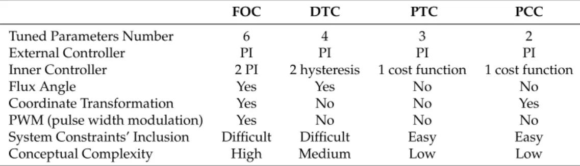
In this section, the control structures and theories are compared. In Figure1, the block diagram of FOC, DTC, PTC and PCC are depicted, respectively. From the figures, four control strategies need a speed PI control for realizing the adjustable speed control. For the inner controllers, FOC uses two current PI controllers; DTC uses two hysteresis controllers and a LUT; PTC takes a cost function to evaluate the torque error and the flux magnitude error and PCC assesses the stator current errors. Both FOC and PCC need coordinate transformation and therefore, flux angle is necessary. DTC and PTC algorithms are in stator reference frame, so no coordinate transformation is needed; however, for the use of LUT, DTC needs the calculation of stator flux angle, though the angle serves for sector selection and its precision of estimation is not that crucial as MPCs. FOC needs a modulator to handle the continuous variables and the other three methods make the modulator absent due to their direct control features. As for the tuning works, FOC has three PI controllers, in which six parameters need to be calculated and tuned. DTC requires four parameters, among which two are for PI controllers and the other two are for hysteresis system. PTC needs three parameters with two for PI controllers and one weighting factor for cost function. PCC needs only two parameters for external PI controller. The cost function needs no weighting factor in PCC method. The comparative items in theory are shown in Table1, where the number of the tuned parameters, the external controller and inner controller, flux angle, coordinate transformation, the use of PWM, system constraints and concept complex are considered for FOC, DTC, PTC and PCC methods.
Table 1.Comparative issues in theory.
FOC DTC PTC PCC
Tuned Parameters Number 6 4 3 2
External Controller PI PI PI PI
Inner Controller 2 PI 2 hysteresis 1 cost function 1 cost function
Flux Angle Yes Yes No No
Coordinate Transformation Yes No No Yes
PWM (pulse width modulation) Yes No No No
System Constraints’ Inclusion Difficult Difficult Easy Easy
4. Implementation and Experimental Comparisons
4.1. Test Bench Description
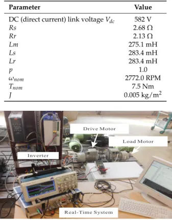
The compared control strategies have been tested on an experimental test bench that consists of two 2.2 kW squirrel-cage induction machines. The main machine is driven by a modified SERVOSTAR620 14 kVA inverter (Radford, VT, USA) which provides full control of the IGBT gates. The other machine, driven by a Danfoss VLT FC-302 3.0 kW inverter (Nordborg, Denmark), is used as a load machine. A self-made 1.4 GHz real-time controller is used. The rotor position is measured by a 1024-point incremental encoder. And the electromagnetic torque is calculated based on (5) instead of directly measured. The parameters of the main motor are given in Table2. Figure2is the picture of the test bench.
Table 2.Parameters of the induction machine.
Parameter Value
DC (direct current) link voltageVdc 582 V
Rs 2.68Ω
Rr 2.13Ω
Lm 275.1 mH
Ls 283.4 mH
Lr 283.4 mH
p 1.0
ωnom 2772.0 RPM
Tnom 7.5 Nm
J 0.005 kg/m2
Figure 2.Test bench description.
4.2. Experimental Comparisons
The first test is developed to show the steady behaviors. The motor is rotating at full speed (2772 rpm) with a full load (7.5 Nm). Figure3presents the results of four methods, including torque and stator current responses. Four methods reach very good results. The calculated current total harmonic distortion (THD) of FOC, DTC, PTC and PCC are 3.2 %, 4.0 %, 3.6 % and 3.4 %. FOC reaches the best current quality at this operating point; however, the other three methods have also good results. FOC and PTC have less torque ripples which are 0.8 Nm and 0.9 Nm, respectively. DTC has slightly larger ripples of 1.2 Nm. When the errors between the reference (7.5 Nm) and the average values of the torque ripples during the observed time are evaluated, FOC has even better results: zero. This is caused by the inner current PI controllers. FOC reaches good current waveforms very easily due to the independent PI control of torque and magnitude of flux, and the use of a modulator. However, more parameters need to be tuned for a cascaded PI control structure.
t
Figure 3.Experimental results: Torque and Stator Current behaviors of four strategies.
The dynamics of control strategies is essential to electrical drives. In the second test,
torque dynamics are compared. The torque reference alters from 0 Nm to the rated value. Figure4a
ripple. Some recent methods contributed to solve this problem by using the multiple switching vectors during one sampling interval [39].
t
(a) Torque Dynamic Response of FOC, DTC, PTC and PCC.
(b) Torque Dynamic Response of PTC: Torque step and Switching Vectors.
Figure 4.Torque responses of four strategies.
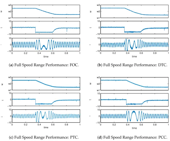
w1
(a) Full Speed Range Performance: FOC.
w1
(b) Full Speed Range Performance: DTC.
w1
(c) Full Speed Range Performance: PTC.
w1
(d) Full Speed Range Performance: PCC.
Figure 5.Experimental results: overall performance of three strategies during speed reverse.
easier to reach good current response. In PTC method, the cost function considers the torque error and the error of the magnitude of stator flux. Therefore, the weighting factor decides the quality of torque behavior and the flux control. The above results show that four strategies reach accepted performance in the whole speed range.
w
Figure 6.Experimental results: sensitivities of Rs and Lm at speed of 100 rpm without load.
In PCC, the reference currents, used in the cost function, are generated by an equation referring to the Lm. Therefore, variation of Lm will directly lead to an incorrect reference value. The other tests show that PCC is very sensitive, even at a higher speed point of 1000 rpm. Figure6b,d,f present the results of Rs influence. DTC loses stability at 2.5 times of the initial value. PTC reaches similar results as DTC. FOC and PCC have very good stability under the variation of Rs. The reason may lie in that PTC and DTC use the voltage model for the prediction and the estimation of the stator fluxes, which are essential to the implementation of both methods. Especially at low speed, Rs has larger influence on the voltage model. Other test results show that at medium- and high speed range, PTC and DTC have much better robustness.
4.3. Analysis of Experimental Comparisons
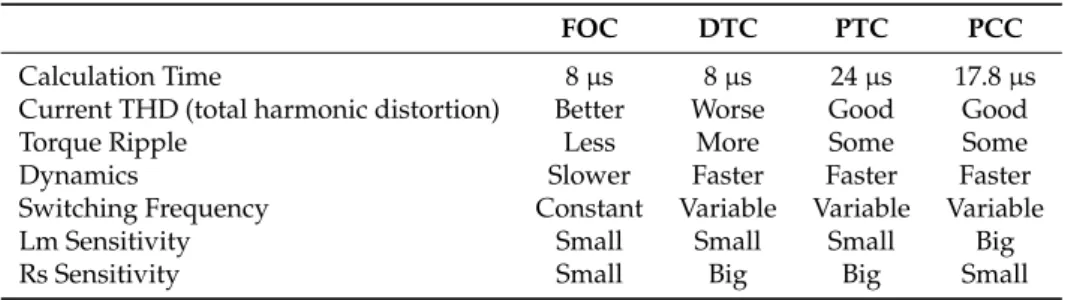
From the experimental results, it is seen that FOC, DTC, PTC and PCC have good performance. In general, FOC has slightly better current THD and smaller torque ripples at almost all operating points. Direct control methods have variable switching frequencies, but they can also be modified by adding SVM to achieve better current THD. FOC takes much longer settling time for the torque-step response. DTC has fast dynamics but larger torque ripples. PTC and PCC have good behavior with less torque ripples and fast dynamics. In the discussion of robustness, PCC is weak with the variation of Lm. The stability of PTC and DTC is limited in a range of the variation of Rs. Also, the implementation time is recorded during the tests. The details are described in Table3, where calculation time, current THD, torque ripples, dynamics, switching frequencies, and sensitivity of Lm/Rs are compared items for all methods.
Table 3.Comparative issues in experiments.
FOC DTC PTC PCC
Calculation Time 8µs 8µs 24µs 17.8µs
Current THD (total harmonic distortion) Better Worse Good Good
Torque Ripple Less More Some Some
Dynamics Slower Faster Faster Faster
Switching Frequency Constant Variable Variable Variable
Lm Sensitivity Small Small Small Big
Rs Sensitivity Small Big Big Small
5. Conclusions
With the presence of FS-MPC, there are mainly three powerful and effective strategies for high performance AC drive systems: FOC, DTC and FS-MPC (PTC and PCC). They have been compared in theory and in experiments. All strategies are different from the theoretical point of view.
FOC is the earliest strategy with cascaded control structure using PI controllers. It has slower dynamics due to the presence of linear current controller. An attractive characteristic of FOC is its fixed switching frequency, which is determined by the presence of the PWM.
DTC appeared later in the market and is a direct nonlinear control strategy with high dynamics. It operates in principle with variable switching frequencies, which is treated as a problem.
Both FOC and DTC are well established and have been recognized by industry as the preferred strategies for high performance drives.
FS-MPC is the newest method developed by the scientific community. FS-MPC is simpler in concept of design. Using a cost function, where system constrains are included, the switching vectors are easily selected. FS-MPC has fast dynamics and good torque response, though it also operates with variable switching frequency as in DTC.
Acknowledgments:This work was supported by the Technical University of Munich (TUM) in the framework of the Open Access Publishing Program.
Author Contributions:F.W. and Z.Z. conceived and designed the paper structure and experiments; F.W. and X.M.
performed the experiments and analysis of results; J.R. and R.K. gave suggestions and made corrections on the discussion and comparison parts; Z.Z. and X.M. wrote the paper.
Conflicts of Interest:The authors declare no conflict of interest.
References
1. Holtz, J. Pulsewidth modulation for electronic power conversion.Proc. IEEE1994,82, 1194–1214.
2. Takahashi, I.; Ohmori, Y. High-performance direct torque control of an induction motor.IEEE Trans. Ind. Appl.
1989,25, 257–264.
3. Mutschler, P.; Flach, E. Digital implementation of predictive direct control algorithms for induction motors. In Proceedings of the IEEE Thirty-Third IAS Annual Meeting Industry Applications Conference, St. Louis, MO, USA, 12–15 October 1998; pp. 444–451.
4. Ambrozic, V.; Buja, G.S.; Menis, R. Band-constrained technique for direct torque control of induction motor.
IEEE Trans. Ind. Electron.2004,51, 776–784.
5. Stando, D.; Kazmierkowski, M.P. Novel speed sensorless DTC-SVM scheme for induction motor drives. In Proceedings of the 8th International Conference on Compatibility and Power Electronics (CPE), Ljubljana, Slovenia, 5–7 June 2013; pp. 225–230.
6. Kazmierkowski, M.P.; Franquelo, L.G.; Rodriguez, J.; Perez, M.A.; Leon, J.I. High-Performance Motor Drives.
IEEE Ind. Electron. Mag.2011,5, 6–26.
7. Zhang, Z.; Wang, F.; Sun, T.; Rodríguez, J.; Kennel, R. FPGA-Based Experimental Investigation of a Quasi-Centralized Model Predictive Control for Back-to-Back Converters. IEEE Trans. Power Electron.
2016,31, 662–674.
8. Rodriguez, J.; Pontt, J.; Silva, C.A.; Correa, P.; Lezana, P.; Cortes, P.; Ammann, U. Predictive Current Control of a Voltage Source Inverter.IEEE Trans. Ind. Electron.2017,54, 495–503.
9. Cortes, P.; Kazmierkowski, M.P.; Kennel, R.; Quevedo, D.E.; Rodriguez, J. Predictive Control in Power Electronics and Drives.IEEE Trans. Ind. Electron.2008,55, 4312–4324.
10. Holtz, J.; Stadtfeldt, S. A predictive controller for the stator current vector of AC machines fed from a switched voltage source. In Proceedings of the International Power Electronics Conference, Tokyo, Japan, 27–31 March 1983.
11. Kennel, R.; Schöder, D. A predictive control strategy for converters. In Proceedings of the Control in Power Electronics and Electrical Drives, Lausanne, Switzerland, 12–14 September 1983; Volume 12, pp. 415–422. 12. Rodriguez, J.; Kazmierkowski, M.P.; Espinoza, J.R.; Zanchetta, P.; Abu-Rub, H.; Young, H.A.; Rojas, C.A.
State of the Art of Finite Control Set Model Predictive Control in Power Electronics.IEEE Trans. Ind. Inform.
2013,9, 1003–1016.
13. Vargas, R.; Ammann, U.; Rodriguez, J. Predictive Approach to Increase Efficiency and Reduce Switching Losses on Matrix Converters.IEEE Trans. Power Electron.2009,24, 894–902.
14. Zhang, Y.; Gao, J.; Qu, C. Relationship Between Two Direct Power Control Methods for PWM Rectifiers Under Unbalanced Network.IEEE Trans. Power Electron.2016,12, 186–197.
15. Geyer, T.; Papafotiou, G.; Morari, M. Model Predictive Direct Torque Control—Part I: Concept, Algorithm, and Analysis.IEEE Trans. Ind. Electron.2009,56, 1894–1905.
16. Preindl, M.; Bolognani, S. Model Predictive Direct Torque Control With Finite Control Set for PMSM Drive Systems, Part 1: Maximum Torque Per Ampere Operation.IEEE Trans. Ind. Inform.2013,56, 1003–1015. 17. Barrero, F.; Prieto, J.; Levi, E.; Gregor, R.; Toral, S.; Duran, M.J.; Jones, M. An Enhanced Predictive Current
Control Method for Asymmetrical Six-Phase Motor Drives.IEEE Trans. Ind. Electron.2011,58, 3242–3252. 18. Wang, F.; Davari, S.A.; Chen, Z.; Zhang, Z.; Khaburi, D.A.; Rodriguez, J.; Kennel, R. Finite Control Set Model
Predictive Torque Control of Induction Machine with a Robust Adaptive Observer.IEEE Trans. Ind. Electron.
2016,58, 1089–1099.
19. Wang, F.; Zhang, Z.; Davari, S.A.; Fotouhi, R.; Khaburi, D.A.; Rodriguez, J.; Kennel, R. An Encoderless Predictive Torque Control for an Induction Machine With a Revised Prediction Model and EFOSMO.
20. Wang, F.; Chen, Z.; Stolze, P.; Stumper, J.F.; Rodriguez, J.; Kennel, R. Encoderless Finite-State Predictive Torque Control for Induction Machine With a Compensated MRAS.IEEE Trans. Ind. Inform. 2014, 10, 1097–1106.
21. Dorfling, M.; Mouton, H.; Karamanakos, P.; Geyer, T. Experimental evaluation of sphere decoding for long-horizon direct model predictive control. In Proceedings of the 19th European Conference on Power Electronics and Applications (EPE’17 ECCE Europe), Warsaw, Poland, 11–14 September 2017; pp. 1–10. 22. Kakosimos, P.; Abu-Rub, H. Predictive Speed Control with Short Prediction Horizon for Permanent Magnet
Synchronous Motor Drives.IEEE Trans. Power Electron.2017,99, 2740–2750.
23. Baidya, R.; Aguilera, R.P.; Acuña, P.; Vazquez, S.; Mouton, H.D.T. Multistep Model Predictive Control for Cascaded H-Bridge Inverters: Formulation and Analysis.IEEE Trans. Power Electron.2018,33, 876–886. 24. Rodriguez, J.; Kennel, R.; Espinoza, J.R.; Trincado, M.; Silva, C.A.; Rojas, C.A. High-Performance Control
Strategies for Electrical Drives: An Experimental Assessment.IEEE Trans. Ind. Electron.2012,59, 812–820. 25. Wang, F.; Li, S.; Mei, X.; Xie, W.; Rodríguez, J.; Kennel, R.M. Model-Based Predictive Direct Control Strategies
for Electrical Drives: An Experimental Evaluation of PTC and PCC Methods. IEEE Trans. Ind. Inform.
2015,11, 671–681.
26. Kennel, R.; Rodriguez, J.; Espinoza, J.; Trincado, M. High performance speed control methods for electrical machines: An assessment. In Proceedings of the 2010 IEEE International Conference on Industrial Technology (ICIT), Vina del Mar, Chile, 14–17 March 2010; pp. 1793–1799.
27. Blaschke, F. The principle of field-orientation as applied to the new transvector closed-loop system for rotating-field machines.Siemens Rev.1972,34, 217–220.
28. Vas, P.Vector Control of AC Machines; Oxford University Press: New York, NY, USA, 1990. 29. Schröder, D.Elektrische Antriebe 2: Regelung von Antrieben; Springer: Berlin, Germany, 1995.
30. Buja, G.S.; Kazmierkowski, M.P. Direct torque control of PWM inverter-fed AC motors—A survey.
IEEE Trans. Ind. Electron.2004,51, 744–757.
31. Nemec, M.; Nedeljkovic, D.; Ambrozic, V. Predictive torque control of induction machines using immediate flux control.IEEE Trans. Ind. Electron.2007,54, 2009–2017.
32. Correa, P.; Pacas, M.; Rodriguez, J. Predictive torque control for inverter-fed induction machines.IEEE Trans. Ind. Electron.2007,54, 1073–1079.
33. Papafotiou, G.; Kley, J.; Papadopoulos, K.; Bohren, P.; Morari, M. Model predictive direct torque control—Part II: Implementation and experimental evaluation.IEEE Trans. Ind. Electron.2009,56, 1906–1915. 34. Rodriguez, J.; Pontt, J.; Silva, C.A.; Correa, P.; Lezana, P.; Cortes, P.; Ammann, U. Direct torque control of
PWM inverter-fed AC motors—A survey.IEEE Trans. Ind. Electron.2007,54, 495–503.
35. Laczynski, T.; Mertens, A. Predictive stator current control for medium voltage drives with LC filters.
IEEE Trans. Power Electron.2009,24, 2427–2435.
36. Stolze, P.; Tomlinson, M.; Kennel, R.; Mouton, T. Heuristic finite-set model predictive current control for induction machines. In Proceedings of the 2013 IEEE ECCE Asia Downunder (ECCE Asia), Melbourne, Australia, 3–6 June 2013; pp. 1221–1226.
37. Holtz, J. Heuristic finite-set model predictive current control for induction machines. In Proceedings of the IEEE International Symposium on Industrial Electronics, Istanbul, Turkey, 1–4 June 2014; pp. 1–6.
38. Holtz, J. The induction motor-a dynamic system. In Proceedings of the 20th International Conference on Industrial Electronics, Control and Instrumentation, Bologna, Italy, 5–9 September 1994; Volume 1, pp. 1–6. 39. Zhang, Y.; Peng, Y.; Yang, H. Performance Improvement of Two-Vectors-Based Model Predictive Control of
PWM Rectifier.IEEE Trans. Power Electron.2016,31, 6016–6030.