Refurbishment of an odour collection and
biofilter treatment system at a municipal solid
waste composting facility in Perth,
Western Australia
TERRY SCHULZAND STUART MCALL
Principal of the Odour Unit Pty Limited, Sydney, Australia and CEO of Southern Metropolitan Regional Council, Perth, Australia
ABSTRACT
This paper discusses a case study at a large, regional Municipal Solid Waste composting plant in Perth, Western Australia, where odour emissions from the facility have resulted in adverse odour impacts in the surrounding community. The plant was designed as a fully-enclosed operation, where all ventilation air from two major processing buildings was to be collected and treated in four large biofilters. The paper describes a detailed investigation into the collection and treatment systems at the plant, which identified deficiencies in the design of both systems. It contains the results of the physical and olfactory investigations, and documents the design for an upgraded collection and biofilter-treatment system that has subsequently been installed.
1 INTRODUCTION
Southern Metropolitan Regional Council owns and operates a large Municipal Solid Waste Composting Facility (WCF) in Canning Vale, Perth, Western Australia. The WCF has a capacity of 150,000 tonnes/year of MSW, using a fully-enclosed, ‘in-vessel’ composting process. It is one of four large MSW composting plants in Australia. The location of the Canning Vale WCF is within a larger Regional Resource Recovery Centre, in the suburbs of Perth, the capital of Western Australia. It has been operating since late-2002.
Perth is a city of approximately 1 million people and is the capital of Western Australia. It has a very hot and dry climate, with summer temperatures regularly above 350 Celcius, and ambient relative humidities that can stay below 40 per cent for several months at a time. As will be explained, these weather conditions can have a strong influence on the design and performance of biofilter-based odour control systems in the area.
Since the commissioning of the Canning Vale WCF a high level of adverse odour impacts has been experienced in the residential areas up to 400 metres from the plant. This situation lead to the development of a strong and well-organised community opposition to the continued operation of the facility, and resulted in increasing pressure from the WA environmental regulatory authority to mitigate the odour emissions.
In February 2006, following a number of earlier attempts to identify the reasons for the unacceptable odour emissions from the plant, investigations commenced on a comprehensive assessment of the design and performance of the entire odour control collection and treatment system at the plant. The methodology used, the findings and the implementation of the findings of that study are described in this paper. The outcome of the study has been a comprehensive re-design of the odour collection system and a total refurbishment of the four biofilters that treat all odour emissions to atmosphere. A full report (The Odour Unit, 2006) documenting the full investigation and results is available on the SMRC website.
2 DESCRIPTION OF THE FACILITY
The Canning Vale WCF was designed using the proprietary ‘Bedminster’ composting system. This system currently receives 120,000 tonnes per year of raw MSW from six local government areas in Perth, and processes it into a fully composted product, in the process separating plastics and metals for subsequent recycling. While there are several different types of MSW composting processes in use around the world, the features of this particular WCF composting process may be summarised as follows:
• A separate MSW receivals hall (the Tipping Building), having a volume of approximately 20,000 cubic metres;
• Four, rotating tunnel digesters, in two banks of two digesters, each bank receiving MSW in the Tipping Building and unloading into different ends of the Aeration Building;
of approximately 100,000 cubic metres. This paper will focus predominantly on the capture and treatment of the odour emissions from this building; • The Load-out wing of the Aeration Building, where fully composted material
is stored and loaded into trucks; and
• The biofilters. There are four biofilters in total. Two smaller units service the Tipping Building, while two larger biofilters receive and treat air drawn from the Aeration Building.
The two Tipping Building biofilters are each fed by two identical fans, each having a capacity of 55,000 m3/hr. One of these fans extracts air from above the inlet to the digester vessels, while the other draws air from within the body of the building. The discharge from each fan enters a packed-column scrubbing unit, designed to remove particulates from the air stream and provide some humidification. The design of the building is symmetrical, having two digesters, two fans, two scrubbers and a biofilter on each side. The original design of the Tipping Building had a single roller-shutter doorway for truck access.
The Tipping Building biofilters (#3 and #4), like the Aeration Building biofilters (#1and #2), are open bed, roofed units, featuring a foul air distribution system based on the use of multiple, slotted PVC pipes buried in gravel, and fed from a longitudinal distribution header duct. Each fan feeds to its own header duct and biofilter section. As a result, each of the two Tipping Building biofilters behaves as two separate units, although visually appearing to be a single biofilter. There is no capability to direct the output from one fan to another section of the biofilter.
The Aeration Building foul air extraction system uses six 72,000 m3/hr fans mounted outside the longest side of the building. Fans 1 to 4 direct air to Biofilter #1, (the largest biofilter – 1,500 m2), while fans 5 and 6 service Biofilter #2 (1,000 m2). The original design of the extraction system involved the six fan-suction ducts terminating inside the wall, approximately five metres above ground level. A number of wall-mounted inlet vents were located along the wall opposite the fans, with the intention of affecting a flow of air laterally across the building. The two ends of the building, containing the odorous digester outlets, the compost conveyors and trommel screens, were not fitted with any form of collection system. The roof height at the ends of the building is higher than in the aeration/maturation section, rising to a maximum height immediately adjacent to the roller shutter doors used to load-out screenings. As with the Tipping Building biofilters, the two Aeration Building biofilters behave as six independent units, each fed by its own fan, with no cross connection between these units.
Table 1.
Canning Vale WCF odour control system summary. Tipping Building Ventilation 20,000 m3 building volume
4 fans, each 55,000 m3/hr 10.5 air changes/hour Tipping Building Biofilters 2 biofilters,
800 m2 bed area per biofilter plenum pipe-in-gravel air distribution wood chip/compost bed medium Aeration Building Ventilation 120,000 m3 building volume
6 fans, each 72,000 m3/hr fan suction ducts in wall cross flow air movement 4.3 air changes/hour Aeration Building Biofilters 2 biofilters,
1,500 m2 and 1,000 m2 bed area plenum pipe-in-gravel air distribution wood chip/compost bed medium
3 PROBLEMS IDENTIFIED IN PREVIOUS STUDIES
As mentioned in Section 1, the operation of the WCF had resulted in the detection of nuisance odours identified as having originated from the facility, up to 400 metres from the plant. Unfortunately the odour complaint records retained by the regulator and SMRC contained little odour descriptor information and therefore did little to identify the source activity within the WCF responsible for the nuisance. Typical descriptors used by complainants were ‘garbage’, ‘waste’, ‘landfill’ and ‘rotting waste’. A previous odour impact assessment study carried out in 2005 identified three key odours that were judged to be responsible for the bulk of the odour complaints. These odours, and their sources within the WCF, are summarised in Table 2.
At the time of this study there appeared to be little understanding of the magnitude of any fugitive odour releases from the Aeration Building.
Table 2.
Odour types within the Canning Vale WCF (2005 Study).
Odour character Likely odour source
Garbage, rotting vegetative material Tipping Floor,
Fruit cake, fermented Fruit Digester discharge area, Aeration floor Stale air or water, rubber tyre Aeration floor
Cheesy, baby vomit Aeration floor
Earthy, damp, mild garbage Biofilters 1 and 2 Forest floor, mouldy, medicinal, Biofilters 3 and 4
4 INVESTIGATION METHODS
The investigation was carried out from February to April 2006. In the course of this investigation a number of methodologies were used to assess both odour impacts and the performance of the odour collection and treatment systems. These are summarised below.
4.1 ODOURIMPACTASSESSMENT
4.1.1 OLFACTORYASSESSMENTATTHESOURCE
This procedure involved The Odour Unit staff assessing the character, intensity and relative emission rate of odours generated within the facility. While subjective in nature, olfactory assessment is able to differentiate between different odour characters. If a clearly defined odour can be detected at a processing source, this enables this same odour and source to be identified if detected downwind of the facility during an ambient odour assessment.
4.1.2 AMBIENTODOURSURVEYS
4.1.3 COMMUNITYFEEDBACK
The scope of work for this project required TOU to interact with community members, as a means of identifying the most problematical odours from the facility. On two occasions samples of odours from a range of processing sources within the WCF were presented to community representatives. The sources assessed were:
• Tipping Floor odour; • Aeration Floor odour;
• Tipping Floor biofilter-treated air; and
• Digestion odour (collected during a digester unloading event).
On the second occasion a community representative was presented with samples collected at source and therefore at ‘full strength’, as well as the same samples diluted to a level likely to be experienced in the community (10 to 20 odour units). This was done to cover the possibility that odour character could change with dilution.
4.2 ODOURCONTROLSYSTEMASSESSMENT
4.2.1 DUCTAIRFLOWMEASUREMENT
Airflow rates in the various ducts in the collection system and into the biofilters were measured using a hot-wire anemometer that measured gas velocity. Where possible the velocity measurements were taken in a straight section of ducting to maximise accuracy of the measurement. All flow readings presented in this report are expressed at the temperature prevailing in the duct.
4.2.2 DUCTPRESSUREMEASUREMENT
Pressure or vacuum was measured simultaneously with velocity measurement in each of the ducts. A simple water-filled manometer was used. The pressure readings were used to determine the pressure duty on each of the 10 fans tested, as well as the back-pressures upstream of each of the cells in the biofilters.
Relative humidity was measured into each of the biofilters, and in the Tipping Floor and Aeration Buildings. Ambient readings were also taken. A TSI VelociCalc 8386A instrument was used for this purpose.
4.2.3 BIOFILTERSURFACEFLOWMEASUREMENTS
This technique has been found to accurately assess relative changes in airflow leaving the surface of a biofilter bed. In this respect it is useful in assessing whether short-circuiting or blockages exist in biofilter beds. A variation in velocity readings of greater than 30 percent would indicate an air distribution problem. However the technique is not able to measure the true airflows leaving a biofilter bed, due to the intrusive nature of the device.
4.2.4 BIOFILTERPRESSURELOSSMEASUREMENTS
A means of quantifying the pressure losses across Biofilter 1 was needed in order to differentiate between the losses through the plenum distribution pipes and the biofilter medium. Two holes were dug in Biofilter 1, one in Cell 1 serviced by Fan 1, and the second at Cell 4. Cell 4 is serviced by Fan 4, which in turn draws particulate-laden air into the biofilter from the final product screening area.
Two sets of manometer tubing were inserted into the bed at these two locations. The first tube at each location was located immediately above the plenum pipe and beneath the shade cloth mesh layer, in the gravel layer, beneath the biofilter medium. The second tube was positioned above the shade cloth. The holes were backfilled and compacted back to as near their original condition as was possible, and pressure readings taken
4.2.5 BULKAIRMOVEMENTASSESSMENT
This study found it imperative that the general airflow patterns be assessed within the Aeration Building. A portable smoke generating machine was used for this purpose. The machine is able to generate copious quantities of smoke for 15-20 seconds at a time, and was sufficient to fill a section of the building and determine airflow patterns. This method was used with great success and was easily able to identify deficiencies in the odour collection system design.
4.2.6 ODOURTESTING
A decision was taken early in this study not to use olfactometry testing. While such testing would have quantified the odour removal performance of the biofilters it was felt that the performance of the biofilters was already known to be sub-optimal.
5 RESULTS
5.1 ODOURIMPACTASSESSMENT
compost piles (a compost odour) and the digester unloading and screening operation (a fermenting/fruity odour). The source of both of these odours was determined to be fugitive odour emissions from the Aeration Building.
It was also determined that incomplete odour destruction in the biofilters was also causing odour impacts, suggesting that the biofilters needed refurbishment.
5.2 DUCTAIRFLOWANDPRESSUREMEASUREMENTS
The results of airflow and pressure testing are shown in Table 3.
Table 3.
Airflow and pressure measurements WCF biofilters (16 March 2006).
Location Airflow (m3/hr) Biofilter delivery pressure (kPa)
Biofilter 1 – Fan 1 45,600 3.9
Biofilter 1 – Fan 2 45,200 3.9
Biofilter 1 – Fan 3 43,900 3.6
Biofilter 1 – Fan 4 40,700 3.9
Biofilter 2 – Fan 5 * *
Biofilter 2 – Fan 6 49,600 4.0
Fan specifications 72,000 4.5 (suction plus delivery)
Biofilter 3 – Fan 11 35,700 1.6
Biofilter 3 – Fan 12 46,500 0.9 **
Biofilter 4 – Fan 9 30,700 1.8
Biofilter 4 – Fan 10 34,500 1.6
Fan specifications 55,000 4.5 (suction plus delivery) * not accessible for measurement
** biofilter bed was dry, scrubber out of service
5.3 FOULAIRHUMIDITYMEASUREMENTS
5.4 BIOFILTERSURFACEFLOW MEASUREMENTS
These results showed erratic and unacceptable airflows across the surface Biofilters 1 and 2. A five-fold variation in surface flows was measured, indicating poor distribution of foul air beneath the biofilter beds.
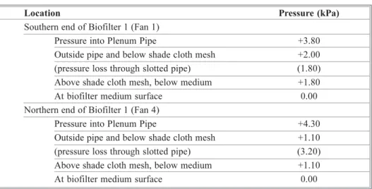
5.5 BIOFILTERPRESSURELOSSMEASUREMENTS
Table 4 contains the results of pressure loss testing in two sections of Biofilter 1. The section serviced by Fan 1 was receiving air typical of that contained in the bulk of the Aeration Building. The section serviced by Fan 4 was receiving air laden with a high particulate loading, drawn from the product screening area.
Table 4.
Pressure losses across Biofilter 1 (5 April 2006).
Location Pressure (kPa)
Southern end of Biofilter 1 (Fan 1)
Pressure into Plenum Pipe +3.80
Outside pipe and below shade cloth mesh +2.00 (pressure loss through slotted pipe) (1.80) Above shade cloth mesh, below medium +1.80
At biofilter medium surface 0.00
Northern end of Biofilter 1 (Fan 4)
Pressure into Plenum Pipe +4.30
Outside pipe and below shade cloth mesh +1.10 (pressure loss through slotted pipe) (3.20) Above shade cloth mesh, below medium +1.10
At biofilter medium surface 0.00
Note: these readings were taken at the reduced airflows shown in Table 3
5.6 BULKAIRMOVEMENTASSESSMENT
The smoke testing carried out inside the Aeration Building revealed highly significant adverse airflows were occurring, as follows:
• There was no consistent airflow pattern evident;
• There was no cross-flow of air from the inlet louvres to the fan suction ducts; • Thermal buoyancy of the air above the compost piles was dominating the
air movement within the building; and
It was concluded from the smoke testing that a thermally induced, positive air pressure was occurring under the roof of the Aeration Building, despite the action of the fans. The pressure at floor level was found to be neutral (neither positive nor negative).
6 DISCUSSION
The technical component of the study were able to provide evidence that confirmed the findings of the odour impact assessment investigations, namely that fugitive odour emissions from the Aeration Building at the WCF were likely to be causing adverse odour impacts in the community.
The cause of these fugitive emissions was determined to be an inability to achieve and maintain negative pressure conditions inside the building, due primarily to two factors - the reduced outputs from the six Aeration Building fans, and the thermally buoyant plumes rising from the compost piles. It was also determined that this situation was being exacerbated by the failure of the existing odour collection system within the building to capture the highly odorous emissions from the digester load-out and screening operations, at each end of the building.
The pressure and flow measurements for the Aeration Building biofilters revealed a serious problem and justified the decision to decrease the fan outputs, in the short term. The results showed excessive pressure losses through the plenum pipe air distribution system, due to a combination of high design air velocities and large loses through the slotted orifices in the pipes. While the pressure loses through the biofilter beds were acceptable, the medium was found to be at the end of its useful life.
7. REFURBISHMENT DESIGN AND PERFORMANCE
As a result of the findings of this study the odour collection system within the Aeration Building and all four biofilters have been refurbished, as follows:
• The fans have been returned to their design airflows;
• A longitudinal header duct has been installed along the length of the building, immediately under the roof apex. All six fans draw from this header duct. Secondary ducts have been installed at each end of the building to capture the air from the digester load-out and screening emissions;
Approxi-mately 50,000 holes have been installed in 560 plenum pipes in the four biofilters;
• The medium in all four biofilters has been replaced; and
• A high-pressure misting system has been installed in the Aeration Building. This system is able to raise the ambient humidity in the building to at least 90%.
This system was commissioned in early 2007 and has been found to achieve strong biofilter performance and measurable negative pressures at all levels and locations within the Aeration Building. While this represents an effective technical solution to the odour emissions problem and has resulted in a sharp decrease in odour complaints, the local community opposition to the continued operation of the WCF is still significant. SMRC is continuing to work with the community to allay its residual concerns.
REFERENCE