Bio-inspired F P G A A r c h i t e c t u r e for Self-Calibration of an
Image Compression Core based on Wavelet Transforms in
E m b e d d e d Systems
Rubén Salvador", Alberto Vidal", Félix Moreno", Teresa Riesgo", Lukás Sekanina*
"Centre of Industrial Electronics, Universidad Politécnica de Madrid
José Gutierrez Abascal, 2, 28006, Madrid, Spain
^Faculty of Information Technology, Brno University of Technology
Bozetéchova 2, 612 66 Brno, Czech Republic
ABSTRACT
A generic bio-inspired adaptive architecture for image compression suitable to be implemented in embedded systems is presented. The architecture allows the system to be tuned during its calibration phase. An evolutionary algorithm is responsible of making the system evolve towards the required performance. A prototype has been implemented in a Xilinx Virtex-5 FPGA featuring an adaptive wavelet transform core directed at improving image compression for specific types of images.
An Evolution Strategy has been chosen as the search algorithm and its typical genetic operators adapted to allow for a hardware friendly implementation. HW/SW partitioning issues are also considered after a high level description of the algorithm is profiled which validates the proposed resource allocation in the device fabric.
To check the robustness of the system and its adaptation capabilities, different types of images have been selected as validation patterns. A direct application of such a system is its deployment in an unknown environment during design time, letting the calibration phase adjust the system parameters so that it performs efcient image compression. Also, this prototype implementation may serve as an accelerator for the automatic design of evolved transform coefficients which are later on synthesized and implemented in a non-adaptive system in the final implementation device, whether it is a HW or SW based computing device.
The architecture has been built in a modular way so that it can be easily extended to adapt other types of image processing cores. Details on this pluggable component point of view are also given in the paper.
1. I N T R O D U C T I O N
Bringing adaptation to embedded systems is a highly demanded feature which will contribute to solve the ever increasing demand on complexity and flexibility. Since deployment may occur in very diverse environments which may be even unknown at design time, it is very difficult to foresee all the possible situations that may arise during system's lifetime.
Therefore, if systems are let to operate on their own a self-adaptation mechanism must be implemented which responds in the presence of changes in the system's environment. Hence, not only Autonomous Systems would benefit from this approach, but, in general, any system (even human-operated devices) that may see its operating conditions change from those specified at design time, whether these changes refer to the input data characteristics (which depend on the environment somehow) or the system's specification itself.
This work proposes self-calibration as a way to accomplish these adaptation needs. A generic bio-inspired adaptive system for image compression tasks which is suitable to be implemented as a System On Chip (SoC) is presented so that its parameters are automatically tuned during a self-calibration phase. Main system blocks are
a Discrete Wavelet Transform ( D W T ) H W core a n d an Evolutionary Algorithm (EA) responsible of adjusting t h e wavelet filters coefficients.
To summarize, this work describes an F P G A - b a s e d architecture which allows a generic artificial vision system to b e a d a p t e d during a self-calibration phase. T h i s allows t h e system t o efficiently deal with images coming from very diverse sources. Hence, it involves t h e a u t o m a t i c on-line design of a complete new set of wavelet (lifting, as introduced below) filters.
T h e rest of t h e p a p e r is organized as follows. Following there is a short introduction t o D W T and EAs as well as a short review of t h e current S t a t e of t h e A r t in t h e topic. Section 2 introduces t h e general architecture of t h e system before Sections 3 a n d 4 go into t h e details of t h e proposed H W architecture and t h e E A running in t h e embedded processor respectively. Afterwards, Section 5 validates t h e proposal showing t h e results achieved before concluding t h e p a p e r in Section 6.
1 . 1 D i s c r e t e W a v e l e t T r a n s f o r m f o r I m a g e C o m p r e s s i o n
Compression s t a n d a r d J P E G 2 0 0 01 relies on t h e D W T for its transform stage, which is a very useful tool for
(adaptive) image compression algorithms, since it provides a transform framework t h a t can b e a d a p t e d to t h e t y p e of images being handled. T h i s feature allows it t o improve t h e performance of t h e transform according to each particular t y p e of image so t h a t improved compression (in t e r m s of quality vs size) can b e achieved, depending on t h e wavelet used.
Sweldens proposed t h e Lifting Scheme (LS) a l g o r i t h m2 , 3 t o c o m p u t e t h e D W T which h a s also simplified t h e
construction of custom wavelets a d a p t e d to specific and different types of d a t a . T h i s is t h e main reason why it is really well suited for t h e task of using an E A t o encode wavelets, since any r a n d o m combination of lifting filters will encode a valid wavelet which guarantees perfect reconstruction.
T h e basic LS, shown in Figure 1, consists of three stages: Split, Predict and Update, which t r y t o exploit t h e correlation of t h e input d a t a t o obtain a more compact representation of t h e signal.4
Figure 1. Lifting scheme
This scheme can b e iterated u p t o n levels, so t h a t an original input d a t a set SQ will have been replaced with t h e wavelet representation {s_n,d_n,... ,d_i}. Therefore, t h e algorithm for t h e LS implementation is:
for j <— l,n do
{sj,dj} «— Split(sj+i)
d3 =d3 -P(Sj )
sj = sj + U(dj)
e n d for
T h e Split stage (also called t h e Lazy Wavelet) divides t h e input d a t a into two smaller subsets, Sj_\ a n d dj_\ which usually correspond with t h e even a n d odd samples. T h e Predict a n d Update stages, also called lifting
filters, are c o m p u t e d as in eq. (1). Although not shown in Figure 1, at t h e end of each transform level two
normalization factors are defined by t h e lifting scheme if, for example, energy conservation is intended.5 An
advantage of t h e lifting scheme is t h a t it defines a perfectly invertible transform by just doing a reversal of t h e forward transform operations order ( U p d a t e , Predict, Merge) and a simple swap of plus a n d minus signs.
d
J-Á
z) =
dÁ
z) +
Pi
z)
sÁ
z)
(1]As eq. (1) shows, the search for an optimum set of coefficients for the lifting filters, P and U, is the problem that needs to be solved by the EA. Besides, since the target implementation are Embedded Systems based on FPGA devices, some restrictions to the computing requirements of the algorithm need to be imposed in order to overcome the supercomputing resources needed by the works currently found in the state of the art.
1.2 Evolutionary Computation for System Optimization
Evolutionary Computation (EC)6 is a sub-field of Artificial Intelligence (AI) that consists of a series of biologically
inspired search and optimization algorithms that evolve iteratively better and better solutions. It involves techniques inspired by biological evolution mechanisms such as reproduction, mutation, recombination, natural selection and survival of the fittest using a population of candidate solutions and bio-inspired operators to search for a target solution.
The algorithm operators are iteratively applied within a loop, where each run is called a generation (g), until a termination criterion is met. So-called variation operators (mutation and recombination) create the necessary diversity and thereby facilitate novelty while selection acts as a force pushing quality since individuals are selected according to the fitness figure scored in the evaluation phase. Mutation delivers a (slightly) modified mutant causing a random, unbiased change, while recombination merges (random) information from two (or more) parents. A general pseudo-code description of an EA is shown in Algorithm 1.
Algorithm 1 General scheme of an Evolutionary Algorithm
1: INITIALIZE population 2: EVALUATE each candidate 3: while not_termination_condition do 4: SELECT parents
5: RECOMBINE (pairs of) parents 6: MUTATE resulting offspring 7: EVALUATE new candidates
8: SELECT individuals for the next generation 9: end while
1.3 Previous work on evolutionary wavelet design
With the introduction of the LS, custom construction of wavelets adapted to specific signal types was made possible. Therefore, instead of dealing with the mathematical construction of new wavelets, an EA can be used to design/optimize the constituent wavelet filters. Our previous work7 features a deep review of the current
State of the Art. However, some brief comments are included here for the readers' convenience.
First approach in evolutionary wavelet design was tackled by Grasemann and Miikkulainen8'9 who made use
of a Coevolutionary (subpopulations evolving in parallel) Genetic Algorithm (GA) that encodes wavelets as a sequence of lifting steps. The results obtained in this work outperformed the considered State of the Art wavelet for fingerprint image compression, the FBI standard based on the D9/7 wavelet, in 0.75 dB. Works10-13 reported
by Babb, Moore et. al., can be considered the current state of the art, outperforming the D9/7 wavelet in 3 dB. They made use of very complex and computationally intensive algorithms, so the training runs were done using supercomputing resources. A standard set of 80 images was used for comparison purposes in these works, the same one as in this work, as will be shown in Section 5)
The use of super-computing resources and the training times needed to obtain a solution gives an idea of the complexity of these algorithms. This issue makes their implementation as a hardware embedded system highly unfeasible, which is precisely what this work addressed in a previous stage of the research,7 to find an adequately
tuned EA able to keep up with the quality of the transforms evolved in the State of the Art, but feasible enough to be implemented in an FPGA. The cut-downs done to the algorithm (a PC-based SW simulator version of the
2. S Y S T E M A R C H I T E C T U R E
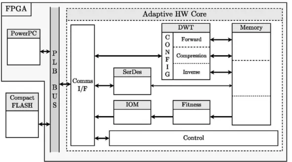
The intended system should be able to perform self-calibration prior to its operating phase. In addition, should a change in the input data specification happen to occur, a new self-calibration phase has to be triggered. A mixed HW/SW architecture has been selected because it offers a reasonable trade-off between performance and flexibility. Figure 2 shows the general architecture of the system, outlining the HW/SW partitioning accom-plished, where the EA is running on the embedded PowerPC processor and the wavelet core is attached to it as a peripheral along with some other HW modules which will be described in detail in Section 3.
FPGA
Compact FLASH
Adaptive HW Core
: J
Comms I / F
SerDes
IOM
D W T
C 0 N F I G
Forward
Compression
Inverse
Fitness
Memory
Figure 2. System level architecture.
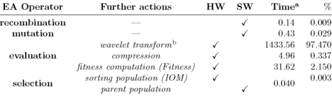
Typical implementations of evolutionary optimization engines in FPGAs place the EA in an embedded processor. With this approach some degree of performance is sacrificed to gain flexibility in the system (needed to fine tuning the algorithm), so that modifications may be easily done to the (software) implementation of the EA (which is, of course, much easier than changing its hardware counterpart). Table 1 shows the partitioning resulting from applying this design philosophy and the results obtained after doing a software simulation for 500 generations, which was addressed in a previous stage of this work.7 Each of the EA operators (as will be
introduced in Section 4) are shown together with further actions to be accomplished: recombination (of the selected parents); mutation (of the recombinant individuals to build up a new offspring population); evaluation (of each offspring individual); and selection (of the new parent population for the next generation).
As it can be extracted from Table 1, the most time consuming and core part of the proposed system, the DWT, is performed in HW to speed-up the adaptation as well as the normal system operation (the result of the previous work yielded a time of 20.479 ms needed to compute a single wavelet transform, whether it is a forward or an inverse one). Besides, the sorting of the population according to the measured fitness is also implemented in HW not only for timing reasons, but also for simplicity, using an Insert Order Machine (IOM) which acts in parallel to the evaluation as results are produced.
Regarding the evaluation, as it consists in measuring the wavelet performance in compression, after doing a forward DWT, a compression stage is needed. Since the remaining compression stages in a typical real compres-sion algorithm are highly time consuming tasks, all wavelet coefficients dj are zeroed, keeping only the trend level of the transform from the last iteration of the algorithm Sj, as suggested in previous works14 dealing with wavelet
filter evaluation for image compression. For 2 levels of decomposition this severe compression is equivalent to an idealized 16:1 compression ratio. This approach was also used in the previous stages of our own work,15 together
Table 1. Algorithm code profiling
E A O p e r a t o r r e c o m b i n a t i o n
m u t a t i o n
e v a l u a t i o n
s e l e c t i o n
F u r t h e r a c t i o n s —
—
wavelet transform0
compression
fitness computation (Fitness) sorting population (IOM)
parent population H W / / / /
sw
/ / /T i m ea
0.14 0.43 1433.56 4.96 31.62 0.040 % 0.009 0.029 97.470 0.337 2.150 0.003
a All results in seconds b Results show c o m p u t a t i o n time for b o t h , forward and
inverse wavelet transform
Figure 3 shows a high-level flow chart of t h e proposed E A together with an abstract view of t h e system to show t h e whole idea of this work: let an EA find an adequate set of coefficients for the lifting filters in order
to maximize the wavelet transform performance from the compression point of view for a very specific type of images.
The system operates by loading a training image from t h e C o m p a c t Flash memory into t h e peripheral private R A M memory (implemented with on-chip F P G A R A M resources). Afterwards, t h e E A is initialized with a set of r a n d o m candidate solutions (the initial parent population). This population goes t h r o u g h the variation operators (recombination and m u t a t i o n ) t o create t h e offspring population t o be evaluated. This phase, evaluation, comprises a forward D W T , t h e ideal compression phase mentioned above, reconstruction of the image (inverse D W T ) and c o m p u t a t i o n of t h e fitness function. Once all t h e offspring population has been evaluated and sorted according t o t h e ranking fitness, t h e new parent population is created after applying t h e (survivor) selection operator.
This prototype system implementation is j u s t a proof of concept, so no considerable effort has been m a d e in optimizing t h e system performance. For instance, as will be analysed in t h e following Section describing the Hardware implementation, t h e lifting scheme is a direct m a p p i n g from its algorithmic description, so no optimizations at t h e level of d a t a dependencies has been considered; neither t h e concurrent access t o t h e internal R A M memories so fitness c o m p u t a t i o n could be m a d e in parallel t o t h e inverse D W T as these results are produced (as would have been t h e optimal solution). T h e only segmentation accomplished has been t h e population sorting phase, which instead of waiting until all t h e individuals h a d been evaluated, sorts t h e m as fitness results are produced. This way, j u s t some clock cycles after finishing t h e evaluation of t h e last individual, will t h e population sorting also be finished.
2 . 1 H W / S W c o m m u n i c a t i o n
The p r o t o t y p e system, based on t h e s t a n d a r d Xilinx embedded development flow, is m a d e u p of a P L B Bus based system with a PowerPC processor. Attached t o this bus is t h e adaptive peripheral, configurable through a set of registers. J u s t two registers have been defined; one for t h e PowerPC t o send d a t a t o t h e peripheral and one for t h e peripheral t o communicate its s t a t u s t o t h e processor. From t h e PowerPC side t h e meaning of these registers is:
• Data/Command register (DC Reg, Write)
— Data. Configuration d a t a (image pixels and filter coefficients) sent t o t h e peripheral.
— Command. Sets t h e peripheral into one of t h e 6 operating modes defined (described in Section 3).
• Status register (SR, R e a d ) . T h e processor polls t h e peripheral s t a t u s waiting for a c o m m a n d t o be finished.
(a) (b) Figure 3. (a): Flow graph of the algorithm, (b) Idea of the algorithm.
reconfigured from t h e P o w e r P C processor according t o t h e proposed EA, since t h e evaluation phase is carried out by t h e very same h a r d w a r e core. T h e only module which could probably need t o be changed is t h a t responsible of the fitness computation, b u t for most image (filtering) processing tasks, it is general enough t o fulfill a d a p t a t i o n requirements.
3. ADAPTIVE W A V E L E T H A R D W A R E C O R E
According to Figure 2 t h e description of each of t h e modules of t h e adaptive wavelet core is as follows:
• DWT. Performs a D W T , which is defined as a set of lifting filter coefficients. A total of 3 U p d a t e and 3 Predict stages of 4 coefficients each can be configured (this a m o u n t s t o 26 coefficients, taking into account t h e 2 normalization factors). Since b o t h lifting filters are structurally equal, a general filtering computing stage has been designed as a direct m a p p i n g of t h e lifting algorithm, which may be configured t o perform a Predict or U p d a t e stage. Besides, a configuration bit sets t h e operating mode of t h e transform, forward or inverse, and another one sets whether t h e ideal compression proposed is done or not.
As shown in previous w o r k s1 6'i r by other authors, for 8 bits per pixel (bpp) integer inputs from an image,
a fixed point fractional format of Q2.10 for t h e lifting coefficients and a bit length in between 10 and 13 bits for a 2 t o 5-level M R A transform for t h e partial results is enough t o keep a rate-distortion performance almost equal to what is achieved with floating point arithmetic. This requires Multiply and Accumulate (MAC) units of 20-23 bits (10 bits for t h e fractional part of t h e coefficients + 10-13 bits for t h e partial transform results). In this p r o t o t y p e implementation t h e d a t a p a t h has been over-dimensioned t o 16 bits fractional part and 10 bits integer part, for a total of 26 bits for t h e result of t h e transform.
• Fitness. C o m p u t e s t h e fitness function, defined as t h e Mean Absolute Error (MAE) (2).
R-lC-l
MAE= — Y,Y.\
I^i)-
K^i)\
(2)where i?, C are the rows and columns of the image and I, K the original and transformed images respectively. Since dividing by RC just means scaling the summation value, it has not been implemented in HW to save resources. Maximum possible fitness value is 255 x (256 x 256) « 28 + 8 + 8 = 224.
• IOM. Insert Order Machine. Sorts the population individuals according to their fitnesses as they are evalu-ated. It keeps track of the particular individual each fitness value belongs to so that when the processor re-trieves the result of the evaluation, the values sent are composed of the tuple (fitnessjvalue, individual Jd). Since maximum fitness value needs 24 bits for its representation, this tuple can be packed in a single 32 bit transfer for populations of up to 256 individuals.
• Communications IF. Module responsible of interfacing with the bus-based system and decoding its commands.
• Control. Global control of the peripheral. Communicates with the Communications IF driving the rest of the peripheral according to the commands decoded.
• Memory and memory controller. Internal peripheral memory implemented with the BRAM blocks available in the FPGA. It has been designed to host:
— The original image (pixels are 8 bit wide integers).
— The result of the DWT plus the compression if configured (28 bits wide fractional format as explained previously).
— The reconstructed image (8 bit wide integers).
• Ser/Des (Serializer/Desearializer). Serializer splits the 32 bits data bus into 4 8-bit wide pixels. The opposite operation is performed by the Deserializer.
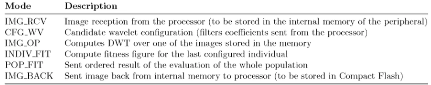
The system operation phases have been clearly defined in the peripheral by the different operating modes it supports, coded as a State Machine in the control module. The communications IF module is in charge of decoding the configuration commands sent by the microprocessor to the peripheral, which will set it into a different operating mode according to the FSM commands driven by the Control module. These modes are described in Table 2.
Table 2. Control State Machine modes
Mode Description
IMG_RCV Image reception from the processor (to be stored in the internal memory of the peripheral) CFG_WV Candidate wavelet configuration (filters coefficients sent from the processor)
IMG_OP Computes DWT over one of the images stored in the memory INDIV_FIT Compute fitness figure for the last configured individual POP_FIT Sent ordered result of the evaluation of the whole population
IMG_BACK Sent image back from internal memory to processor (to be stored in Compact Flash)
4. P R O P O S E D E V O L U T I O N A R Y A L G O R I T H M D R I V I N G A D A P T A T I O N
As explained in Section 2 the embedded PowerPC processor is responsible of running the EA, in particular, an Evolution Strategy (ES). Previous works done by other authors made use of supercomputing resources to evolve state of the art performing wavelets. Since this implementation is targeting embedded systems, several and severe simplifications were proposed as compared to these works. Besides, another simplification to the standard, simplest ES, has been accomplished. This proposal and the thorough set of tests performed to tune the ES and find a suitable set of parameters for evolution to succeed, in the case of adapting the DWT to fingerprint images, can be found in our previous work.7 The summary of these proposals and the resulting ES
are reproduced here for the shake of clarity, pointing to the particular conference papers where they were first presented.
The first simplifications18 to the algorithm as compared to the previously reported State of the Art are
summarized below:
1. Single evolving population opposed to the parallel populations of the coevolutionary genetic algorithm proposed in.9
2. Use of uncorrelated mutations with one step size19 (introduced in Section 4.1) instead of the overcomplex
CMA-ES method used by Babb et. al.11-12
3. Evolution of one single set of coefficients for all MRA levels.
4. Ideal compression for the evaluation of the transform. Since doing a complete compression would turn out to be an unsustainable amount of computing time, the simplified evaluation method of Grasemann et al.9
was further improved with the proposed ideal compression.
Finally, the last two simplifications were accomplished and validated in a second stage of our work.15
1. Uniform random distribution. Instead of using a Gaussian distribution for the mutation of the object parameters (see Section 4.1 for a description of the parameters), a Uniform distribution was tested for being simpler in terms of the HW resources needed for its implementation.
2. MAE as fitness function. PSNR is the quality measure more widely used for image processing tasks. But, as previous works in image filter design via EC show,20 using MAE gives almost identical results because
the interest lies in relative comparisons among population members.
4.1 I m p l e m e n t a t i o n of t h e E S
This Section describes the ES implemented in the PowerPC processor. In the analysis of previous works done in Section 1.3, ESs are the chosen type of EA in the State of the Art results, so this decision seems reasonable. However, since works using a Genetic Algorithm also performed well, we decided to make use of the wavelet encoding proposed in those works, the lifting scheme, which is also more suitable for an embedded system implementation.
The canonical versions of the ES are denoted by (p/p, A)-ES and (p/p+X)-ES, where p denotes the number of parents (parent population, PM), p < p the mixing number (i.e., the number of parents involved in the procreation
of an offspring), and A the number of offspring (offspring population, P\). The parents are deterministically selected from the set of either the offspring, referred to as comma-selection (p < A stands), or both the parents and offspring, referred to as plus-selection. The former, comma-selection, is generally preferred in ES over the
plus-selection, where the selection pool consists of the p+X individuals of the parent and offspring populations, for
being, in principle, able to leave (small) local optima and not letting survive misfit parameters of the individuals. Therefore, no elitism is allowed.
Standard representation of the individuals in ESs, (x\,..., xn, a), is composed of a set of object parameters
Xi to be optimized, and a single strategy parameter a, which determines the degree of perturbation of the
mutation operator. Therefore, the encoding of each wavelet individual is of the form:
where each P¿, £/¿ is made up of 4 coefficients and ki are single coefficients, yielding the 26 fixed point coefficients introduced in previous Section. As a comparison, standard D9/7 wavelet uses (Pi, Ui,P2, U2,kl,k2).
One of the particular features of ESs is that the individual step sizes of the variation operator for each coordinate is governed by self-adaptation. This self-adaptation of the step size a, also known as mutation
strength (i.e. standard deviation of a normal distribution), implies that a is also included in the chromosomes,
undergoing variation and selection itself (co-evolving along with the solutions).
For real-valued search spaces, mutation in ESs is normally performed by adding a normally (Gaussian) distributed random value to each component under variation (i.e., to each parameter encoded in the individuals). In this work it has been implemented using the standard C-based rand() and srandQ functions, which yield a Uniform distribution in the range (0 . . . RAND-MAX) {RAND.MAX = 2147483647) and seed the generator, respectively. To obtain a Normal distribution N(0,1) two Uniform distributions U, V are needed according to the Marsaglia Polar Method,21 described below:
zi = d V 2 x log (fl) x
-22 = ±v /- 2 x l o g ( P ) x ^
being U, V two independent uniform distributions [7(0,1) and R = U2 + V2
obtained which follow two standard Normal distributions.
For the survivor selection after creating A offspring and calculating their fitnesses, the best p individuals are selected deterministically for the new parent population based on the ranking of the individuals' fitness. The selection scheme used is the comma-selection.
Regarding the recombination process, intermediate recombination has been selected, where the object and strategy parameters of the selected parents are averaged. The selection of these p recombinants is done randomly from the parent population.
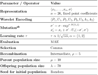
Table 3 summarizes the proposed ES in charge of looking for the optimum coefficients throughout the search space.
5. R E S U L T S 5.1 E x p e r i m e n t a l S e t - U p
The prototype system has been implemented in a Xilinx ML507 board featuring a Virtex-5 FPGA (XC5VFX70T) with an embedded PowerPC® 440 processor. Since the algorithm has already been validated in our previous works making use of a software version of the system, the aim of this Section is to validate the FPGA imple-mentation.
5.2 A d a p t a t i o n R e s u l t s
5.2.1 Evolution results for fingerprint images
The specific type of images chosen to demonstrate the adaptation capabilities of the system are fingerprints, in particular, the first set of 80 images of the FVC200022 fingerprint verification competition. Images were
greyscale, sized 300 x 300 pixels at 500 dpi resolution. One random image was used for training and the whole set of 80 images for testing the best evolved individual in each optimization process. Every result shown in this work is compared with the performance obtained with the standard D9/7 wavelet. Since evolution time depends on the time spent evaluating candidate solutions, which involves the whole chain of forward DWT + compression
+ inverse DWT, the smaller the images, the lower the time to do a transform and hence achieve adaptation.
For this reason, images were resized to 256 x 256.
Table 4 gathers the performance (MAE) results of the adaptation of the system for the training images and for a couple of test images of the same type not seeing during evolution to demonstrate the generality of the result. The best evolved individual (Evo-FP) is compared with the standard D9/7, clearly showing a performance improvement.
(4)
Table 3. Proposed Evolution Strategy
Parameter / Operator
Representation
Wavelet Encoding
Mutationa b
Learning rate T Evaluation Selection Recombination
Parent population size Offspring population size Seed for initial population
Value
\X\, . . . , Xn, 0~j
n = 26, fixed point coefficients {PuUuP2,U2,P3,U3,kuk2)
a' = a- e x p - ^0'1)
x¡ = Xi + a' • Ui(-a',a')
T oc 1/A/CTO, a = {1, 2}
MAE
Comma
Intermediate, p = 5
H= 10
A = 70
Random
a N(0,1): draw from the standard normal distribution b Ui(— a', a'): separate draw from the discrete uniform
dis-tribution for each variable i
Table 4. Results for fingerprint images
Wavelet Training image Tl Test image Tl # 1 Test image Tl # 2
D9/7 6.64 6.80 7.28 Evo-FP 4.97 5.05 5.96
5.2.2 Test evolved wavelet on a different t y p e of images (T2)
Another test has been performed simulating the case of a change in the input type of images. In this case, Magnetic Resonance Images (MRI) have been used. Table 5 gathers the results of applying the standard D9/7 wavelet (first row) over this new type of images and its comparison with the performance obtained with the current wavelet transform configured in the system, Evo.FP, which is adapted to fingerprints (second row). As expected, since this wavelet was adapted to deal with a different type of images the performance could improve if a new self-calibration phase is triggered. The results after the system adapts itself for this new type of input data are shown in the last row of Table 5.
Table 5. Results for MRI images
Wavelet Training image T2 Test image T2 # 3 Test image T2 # 4
D9/7 9.14 8.08 7.58 Evo-FP 8.15 7.46 6.76 Evolved 7.96 6.95 6.57
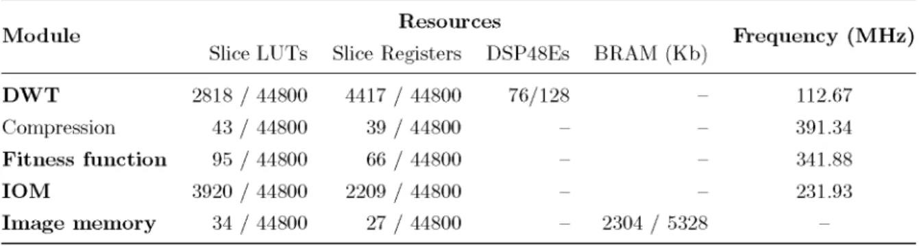
5.3 I m p l e m e n t a t i o n R e s u l t s
Table 6. Implementation results for the main modules in the system.
Module
D W T
Compression
Fitness function IOM
Image memory
Slice LUTs
2818 / 44800 43 / 44800
95 / 44800 3920 / 44800 34 / 44800
Resources
Slice Registers DSP48Es
4417 / 44800 39 / 44800
66 / 44800 2209 / 44800 27 / 44800
76/128 -BRAM (Kb) -2304 / 5328
Frequency (MHz) 112.67 391.34 341.88 231.93
-5.3.1 Adaptation time
Measured latency of the DWT module is 56 clock cycles. Therefore, for the size of images used for evolution, the number of clock cycles needed to compute the first forward transform level, Sjj — 1, is:
((256 x 256) + 56) x 2 = 131184
Equivalently, for the second transform level, s¿-2, where the smaller subset (compared to the original input
Sj) Sj-i is used as input, the number of clock cycles needed for its computation is 32880. This means that a
whole 2-level forward DWT takes 164064 clock cycles. The same analysis can be applied for the 2-level inverse inverse DWT, since the computation stages are right the same. As for the compression module, it needs to retrieve the whole image from memory to perform its operation, which yields 256 x 256 = 65536 clock cycles. The same applies for the fitness module.
Based on this previous analysis, it can be concluded that the evaluation of one individual takes 164064 + 65536 + 164064 + 65536 = 459200 clock cycles. If system frequency is set to 100 MHz, 4.592 ms are needed for the evaluation of a single candidate wavelet. Since system is let to evolve during 1000 generations, doing 70 evaluations per generation, around 5.34 minutes are needed for evolution to finish.
Previous timing analysis applies to the adaptive wavelet core timing. However, ES running in the PowerPC processor will add more time to the evolution. The final time measured increases to 12 minutes, which means that the system is able to adapt to a new type of input data in this time. This may look like a huge amount of time, but as shown in our previous work,7 between generations 100 and 300 the system has already evolved a
better solution. This reduces the effective evolution time to between just 1.2 and 3.6 minutes.
6. C O N C L U S I O N
A self-adaptive FPGA-based architecture for image compression in embedded systems has been proposed and validated. The system improves existing standard wavelets like D9/7 used in JPEG2000. Besides, it is able to self-adapt to changes in the type of input data (images) being dealt with. As Section 5.2 shows, the system is able to optimize standard compression performance. While the quality of results depends on a particular application domain, better than the standard wavelets are still obtained in both cases tested.
Future work will center in improving system performance. The timing analysis and the architecture descrip-tion clearly show that a great amount of time can be saved if a better memory architecture and system pipelining is used, since compression could be done without previously saving the forward DWT in memory. The same applies for the inverse DWT and the fitness computation. This results in 164064 + 164064 = 328128 clock cycles for the evaluation of an individual, which means saving around 29% of the HW computation time.
Besides, a Uniform mutation may also be used for the mutation of the strategy parameter, a. This simplifi-cation could lead to further reduce computation time. However, optimization performance of the evolutionary search should be checked as was done previously with the object parameters.
A C K N O W L E D G M E N T S
This work was s u p p o r t e d by t h e Spanish Ministry of Science and Research under t h e project DR.SIMON (Dy-namic Reconfigurability for Scalability in Multimedia Oriented Networks) with number TEC2008-06486-C02-01. Lukas Sekanina has been s u p p o r t e d by M S M T under research p r o g r a m MSM0021630528 and by t h e grant of the Czech Science Foundation G P 1 0 3 / 1 0 / 1 5 1 7 .
R E F E R E N C E S
1. D. T a u b m a n and M. Marcellin, JPEG2000: Image Compression Fundamentals, Standards and Practice. Springer, 1 ed., Nov. 2001.
2. W. Sweldens, "The lifting scheme: A custom-design construction of biorthogonal wavelets," Appl. Comput.
Harmon. Anal. 3(2), p p . 186 - 200, 1996.
3. W. Sweldens, "The lifting scheme: a construction of second generation wavelets," SIAM J. Math.
Anal. 29(2), p p . 511-546, 1998.
4. W. Sweldens, "The lifting scheme: a new philosophy in biorthogonal wavelet constructions," in Wavelet
Applications in Signal and Image Processing III, A. F . Laine and M. Unser, eds., 2 5 6 9 ( 1 ) , p p . 68-79, SPIE,
1995.
5. G. Uytterhoeven, Wavelets: software and applications. P h D thesis, D e p a r t m e n t of C o m p u t e r Science, K.U.Leuven, Leuven, Belgium, Apr. 1999. Roose, Dirk and Bultheel, A d h e m a r (supervisors).
6. A. Eiben and J. Smith, Introduction to Evolutionary Computing, Springer, Oct. 2008.
7. R. Salvador, F . Moreno, T. Riesgo, and L. Sekanina, "Evolutionary approach t o improve wavelet transforms for image compression in embedded systems," EURASIP Journal on Advances in Signal Processing 2 0 1 1 , pp. 1-20, 2011.
8. U. G r a s e m a n n and R. Miikkulainen, "Evolving wavelets using a coevolutionary genetic algorithm and lift-ing," in Genetic and Evolutionary Computation GECCO 2004, Lecture Notes in Computer Science 3 1 0 3 , pp. 969-980, Springer Berlin / Heidelberg, 2004.
9. U. G r a s e m a n n and R. Miikkulainen, "Effective image compression using evolved wavelets," in Proceedings
of the 2005 Conference on Genetic and evolutionary computation, GECCO '05, p p . 1961-1968, ACM, (New
York, NY, USA), 2005.
10. B. B a b b and F . Moore, "The best fingerprint compression s t a n d a r d yet," in IEEE International Conference
on Systems, Man and Cybernetics, 2007. ISIC, p p . 2911-2916, 2007.
11. B. B a b b , F . Moore, M. Peterson, T. H. O'Donnell, M. Blowers, and K. L. Priddy, "Optimized satellite image compression and reconstruction via evolution strategies," in Evolutionary and Bio-Inspired Computation:
Theory and Applications III, 7 3 4 7 , p p . 7 3 4 7 0 0 - 1 0 , S P I E , (Orlando, FL, USA), May 2009.
12. B. J. B a b b , F . W . Moore, and M. R. Peterson, "Improved multiresolution analysis transforms for satellite im-age compression and reconstruction using evolution strategies," in Proceedings of the 11th Annual Conference
Companion on Genetic and Evolutionary Computation Conference: Late Breaking Papers, p p . 2547-2552,
ACM, (Montreal, Qubec, C a n a d a ) , 2009.
13. F . W. Moore and B . B a b b , "A differential evolution algorithm for optimizing signal compression and recon-struction transforms," in Proceedings of the 2008 GECCO conference companion on Genetic and
evolution-ary computation, p p . 1907-1912, ACM, (Atlanta, GA, USA), 2008.
14. J. Villasenor, B . Belzer, and J. Liao, "Wavelet filter evaluation for image compression," IEEE Transactions
on Image Processing 4, p p . 1053 -1060, aug 1995.
15. R. Salvador, F . Moreno, T. Riesgo, and L. Sekanina, "High level validation of an optimization algorithm for t h e implementation of adaptive wavelet transforms in F P G A s , " in Digital System Design: Architectures,
Methods and Tools (DSD), 2010 13th Euromicro Conference on, p p . 96-103, 2010.
16. M. Martina, G. Masera, G. Piccinini, and M. Zamboni, "A VLSI architecture for I W T (integer wavelet transform)," in Proceedings of the 43rd IEEE Midwest Symposium on Circuits and Systems, 2000., 3, pp. 1174-1177 vol.3, 2000.
18. R. Salvador, F. Moreno, T. Riesgo, and L. Sekanina, "Evolutionary design and optimization oí wavelet transforms for image compression in embedded systems," in Proceedings of the 2010 NASA/ESA Conference
on Adaptive Hardware and Systems (AHS), pp. 171-178, IEEE Computer Society, jun. 2010.
19. H. Beyer and H. Schwefel, "Evolution Strategies. A comprehensive introduction," Natural Computing 1, pp. 3-52, Mar. 2002.
20. Z. Vasicek and L. Sekanina, "An evolvable hardware system in Xilinx Virtex II Pro FPGA," Int. J. Innov.
Comput. Appl. 1(1), pp. 63-73, 2007.
21. G. Marsaglia, "Normal (gaussian) random variables for supercomputers," The Journal of Supercomputing 5, pp. 49-55, 1991. 10.1007/BF00155857.
22. D. Maio, D. Maltoni, R. Cappelli, J. Wayman, and A. Jain, "FVC2000: fingerprint verification competition,"